A pipe bend in the oil and gas industry is a curved section of piping used to change the direction of fluid flow, typically by 45° or 90°. Pipe bends are designed to withstand high pressure, temperature, and mechanical stresses while maintaining smooth and efficient flow. They are commonly used in pipelines, process plants, refineries, and other piping systems to route fluids around equipment and structures.
The following article will explain the maximum allowable internal pressure capabilities for pipe bends used in the oil and gas industries.
Two types of bends are quite common in the oil and gas industries. Normal pipe bends as a pipe fitting and mitre bends.
1. Pipe Bends and Elbows
Minimum Required Wall Thickness (tm) of Pipe Bends
While the concept of calculating the tm (t+c) of pipe bends is similar to the calculation of pipe wall thickness, the designer shall consider the “I” factor for the intrados and extrados of the bend as follows, as per ASME B31.3:
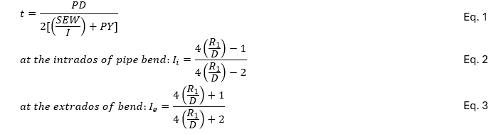
First, it is shown what the factor “I” is. Then, the effect of this factor on the maximum allowable internal pressure (Pm) of pipe bends is evaluated.
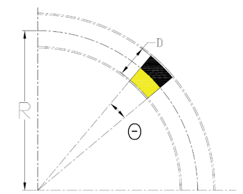
Figure 1 illustrates a simple bend under Internal Pressure (Pi). As shown, a radial pipe segment is divided into two zones: the inside zone is shown in yellow, and the outside zone is shown in black.
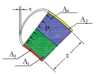
The Pi acts on the area named Ai and Ae, while the hops stress (Sh) acts on the A1 and A2, as shown in Figure 2.
Thus:
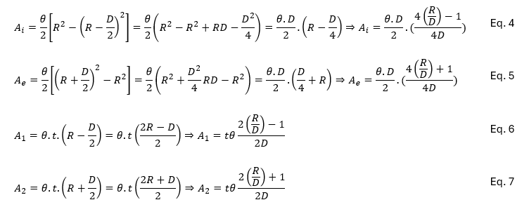
At the intrados of pipe bend:
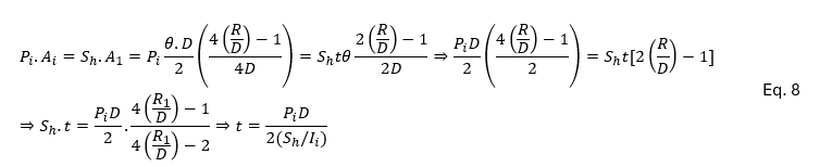
At the extrados of pipe bend:
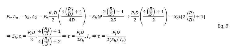
By comparing Equations 8 and 9 together, it is clear that the required THK. of a pipe bend at the intrados is greater than the required value at the extrados of the bend. Thus, ASME B31.3, ASME NM.1, and ASME NM.2 consider the Pm at the intrados of pipe bends. If Eq. 2 is simplified, we have:

Where R is the bend radius of the welding elbow or pipe bend, and r is the radius of pipe. It should be noted that ASME NM.2 replaces I with m in Equations 2-3-7 and 2-3-8.
To evaluate Pm, with respect to Equations 9 and 10, we have:

Based on Eq. 11, for FRP pipes (ASME NM.2, Eq. 2-3-10) and HDPE pipes (ASME NM.1, Eq. 2-3-7):

For steel pipe bends, as per ASME B31.3 [Eq. (4b)], the designer shall consider the effects of the factors E and W, and replace the t by (T-c). Thus:

Where:
E is the quality factor.
W is the weld joint strength reduction factor.
c is the sum of the mechanical allowances.
T is the wall thickness of pipe bend.
2- Miter Bends
Sometimes mitered pipe ends are connected together to make a change in the direction of piping. These mitered connections are known as mitered bends. Here, it is shown when a miter bend requires design consideration and what the requirements are.
Some standards, codes, and studies state that if the angular offset is 3 degrees or less, there is no need for any design consideration as mitered bend. For instance:
- ASME B31.3-2022, Clause 304.2.3: An angular offset of 3 degrees or less (angle α in Figure 3) does not require design consideration as a miter bend.
- ASME NM.1-2018, Clause 2-3.2.4, Section (e): Mitered joints of 3 degrees or less shall not require redesign consideration as mitered elbows.
- Dynaflow Research Group, “Finite Element Analysis of Filament Wound Pipe Coupler”
*It should be noted that other standards or codes may specify other requirements.
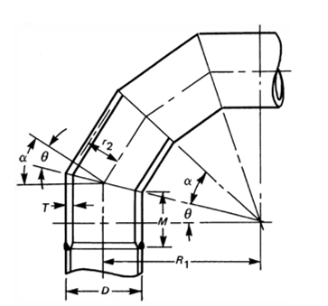
As the pipe direction changes, the geometry changes. Therefore, in this case, the effects of the discontinuity area and, subsequently, the discontinuity stresses on the pipe and mitered elbow shall be evaluated.
As shown in the relevant discontinuity stress post, the effective zone is a key parameter in discontinuity areas. It is good practice to consider βX=1, where the magnitude of shear stress decreases to less than 20% of its maximum value. Thus:

According to Figure 4, the hatched area is the smallest existing area in a mitered elbow, and therefore, it is more vulnerable than other areas to internal pressure. Therefore, the design criteria shall ensure that this area can resist Pi.
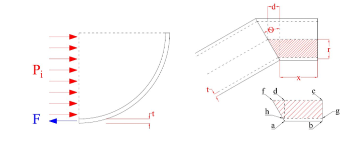
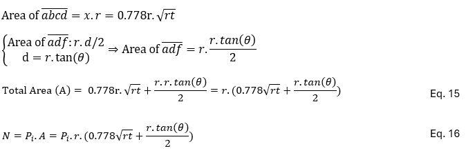
The Reaction Force (F) acts on the Area of “abgh” as shown in Figure 4, and its area is as follows:

Where:
t is the wall thickness of the pipe
Multiple Miter Bend or Single Miter Bend with Q not larger than 22.5°:
To avoid failure of the miter elbow, Pm shall be calculated as follows:
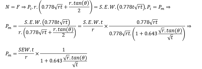
If the numerator and denominator of the fraction are multiplied by t, then:

Now, if the “t” and “r” are replaced with “T-c” and “r2”, respectively, then we have:

This is the mentioned Equation (4a) of ASME B31.3, Where:
T is the miter pipe wall thickness
r2 is the mean radius of the pipe
c is the sum of mechanical allowances
FRP pipes (Eq. 18) have no W and E factors, and if r is replaced with r2 in that equation, the Pm for FRP miter bends will be as follows:

The above equation is Eq. (2-3-9) of ASME NM.2.
It should be mentioned that for polyethylene (PE) pipes, the long-term Poisson ratio is 0.45. If this value is used, the equation 14 will be:

By considering the new value of x in the above equations, Equation 20 will be as follows:

The above equation is the referenced Equation (2-3-6) of ASME NM.1.
Equations 19, 20 and 22 are the criteria of the maximum allowable internal pressure of miter bends for steel, FRP, and HDPE pipes, respectively. While these criteria determine the Pm for miter bends, the value of Pm shall not be greater than the maximum allowable internal pressure of pipe bends (equations 12 and 13).
Single Miter Bend with θ larger than 22.5°:
ASME NM.2 and ASME B31.3 choose a more conservative approach for single miter bends with θ greater than 22.5 degrees. They almost double the 0.643 value and increase it to 1.25.
Therefore, Pm for a single miter bend as per ASME B31.3 (Eq. 4c) and ASME NM.2 (Eq. 2-3-11) is, respectively, as follows:

It should be noted that ASME NM.1 limits the angle θ to 22.5 degrees.
Effective Length of the Miter-Bend Discontinuity (M)
It should be mentioned that the required thickness of steel and FRP miter bends shall be continued for an adequate distance, where the effects of discontinuity could be neglected. This distance is called “M” in ASME B31.3 and ASME NM.2. According to Figure 3, M is as follows:

Based on Figure 5 of the post “What is Discontinuity Stress with respect to Pipe Stress analysis?”, when βX=3.2, the values of shear force and bending moment are less than 95% of their maximum values. Thus, it is an acceptable distance for M:
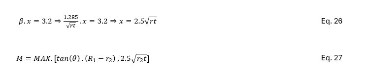
This is the referenced criterion in “ASME B31.3, para. 304.2.3, Clause (c)”, and “ASME NM.2, para 2-3.3.2, Clause (c)”.
References
- 1- ASME B31.3: Process Piping Code
- 2- ASME NM.1: Thermoplastic Piping Systems
- 3- ASME NM.2: Glass-Fiber-Reinforced Thermosetting-Resin Piping Systems
- 4- AWWA M55: PE Pipe – Design and Installation
- 5- “Pipe Stress Engineering” – L.C. Peng and T.L. Peng
- 6- “Finite Element Analysis of Filament Wound Pipe Coupler” – Dynaflow Research Group
Thorough treatment of allowable pressure at bends; the extrados thinning is easy to overlook until a hydro-test flags it. From a takeoff angle, bend thickness and any schedule bump drive material weight and cost, so on our pipe takeoffs at The Virtual Estimation (thevirtualestimation.com) we quantify fittings by actual wall thickness, not nominal size.
it’s nice to know. Thanks for sharing