
Pipe bends are fundamental components in the piping and pipeline industries. They offer the ability to change the direction of pipelines efficiently. Pipe bends are also popular as pipeline bends as they are widely found in pipeline applications. Pipe Bends and Elbows are not the same. Piping elbow is an engineered pipe fitting while pipe bends are fabricated items. Pipe elbows are extensively used in piping applications but piping bends find wide application in oil and gas pipelines. In this article, we will learn about the various types of pipe and pipeline bends.
What is a Pipe Bend?
A pipe bend is an offset or change in direction of the pipe from its original route. We all know that pipelines run several kilometers of distance transporting oil, gas, or water from one point to another. The distance is obviously not straight throughout. So, pipe bends are introduced to change the pipeline direction. They also provide flexibility to the piping or pipeline system.
Types of Pipe Bends
Pipe bends are classified depending on the method of manufacturing and bend radius. Pipelines use large-diameter bends ranging from 3D and above. Let’s find out the different types of pipe and pipeline bends that are widely used in the oil and gas industries. Broadly, there are four types of bends as mentioned below:
- Hot Bends or Induction Bends
- Cold Bends or Field Bends, and
- Elastic Bends
- Miter Bends
Hot Bends or Induction Bends
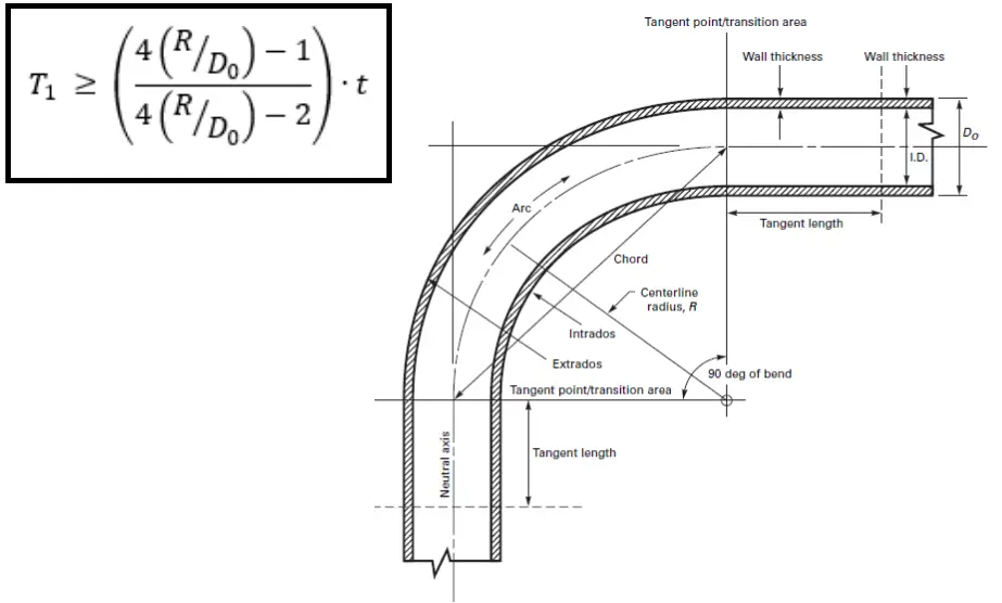
Hot bends, also known as induction bends are manufactured in a temperature-controlled environment in hot conditions using an induction bending process. The American standard ASME B16.49 provides the guidelines for Factory-Made, Wrought Steel, and Buttwelding Induction Bends for Transportation and Distribution Systems. Once the parent pipe of a specified thickness is heated using an induction coil, the induction bending machine applies pressure to make the intended pipe bend. Note that, the formed pipe bend needs to be free from buckling, cracks, or other evidence of mechanical damage.
However, when the hot bending process causes some pipe thickness changes while bending. In general, the pipe bend thickness at intrados becomes thicker while at the extrados becomes thinner. Clause 404.2.3 of ASME B31.4 stipulates that the pipe diameter at any point shall not be reduced by more than 2.5% of the nominal diameter, and the completed bend shall pass the specified size of a pig.
Additionally, ASME B16.49 provides an equation (Fig. 1) to satisfy the minimum thickness of the pipe bend at the intrados (inside surface). Also, the thickness at the extrados or at the neutral axis shall not be less than the parent pipe design minimum thickness.
In general, the use of hot bends is avoided in pipeline systems as far as possible. Only when the installation of field bends is not practical due to space limitations, cold bends are used. Usually, the minimum bend radius for hot bends for pipe size 6 inches NPS and above is kept 5D, and for lower sizes, the same is kept 10D (D=Pipe NPS)
Cold Bends or Field Bends
Cold bends or Field Bends are produced by applying very high force to help bring the pipe to its final shape. There are different bending methods that can be used to form a cold pipe bend as mentioned below:
- Rotary Draw Bending
- Mandrel Bending
- Compression Bending
- Roll Bending
As per clause 404.2.2 of ASME B31.4, the Field bends or cold bends are defined as the pipe bends made in the field during pipeline construction to allow the pipe to conform to the ditch contour. They include horizontal bends and vertical bends (sags and overbends) to accommodate direction changes in direction, and combination bends.
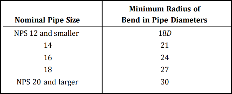
Owing to the fact that the cold pipe bends are not manufactured in a controlled environment, adequate precautions must be exercised to ensure cold bends are free from buckling, cracks, or other evidence of mechanical damage. The same clause of ASME B31.4 also stipulates the minimum radius of filed cold bends as given in Fig. 2 below.
Clause 434.7.1 (e) of ASME B31.4 states that when the bends are made in a longitudinally welded pipe, attention should be given to ensure that the longitudinal weld is located on or near the neutral axis of the bend.
Even though ASME B31.4 provides the minimum bend radius as 18D to 30D, in practical application the used cold bends for pipeline systems are 25D to 60D.
Elastic Bends
Elastic bends are bends produced by bending the pipe without exceeding its yield strength. For buried pipelines, these types of bends are widely used to get small directional changes while pipeline routing. Elastic pipeline bends help in layout to achieve vertical changes due to the change in the elevation of the pipe trench. However, to fit the pipe into the ditch, they are also used to achieve horizontal change in direction.
The minimum elastic bending radius (Rmin) of a buried pipeline is calculated using the formula;
Rmin=(E*D/2*Sb)
Here
- E = Young’s Modulus of the Pipe Material
- D = Pipe Outside Diameter
- Sb =Bending Stress
In general, the minimum elastic bend radius for practical pipeline applications is kept at 500*D.
Miter Bends
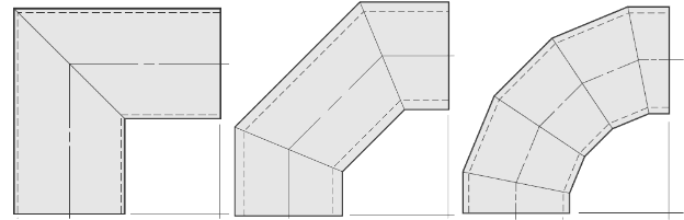
Miter bends are custom-fabricated bends to meet specific project requirements. They are produced by cutting pipe ends (mitering) at an angle and joining the pipe ends by welding. Mitered bends are used for larger pipes when standard pipe elbow fittings are not easily available and costly. They are usually fabricated in 2, 3, or 5 pieces. For getting a 90-degree direction change, two 45-degree pipe cuts or three 22.5-degree pipe cut pieces will be required. Miter bends can be produced with various radii of curvatures out of which 1D, 1.5D 2D, 3D, 5D, 6D, 8D, and 10D are quite common. However, due to very high-pressure drops in mitered bends, their applications are limited. Fig. 3 below shows a typical miter pipe bend.
Hot Bend vs. Cold Bends
The major differences between hot bend and cold bend are already discussed here.
Pipe Elbow vs. Pipe Bend
Differences between Pipe Elbow and Pipe Bend are already discussed and you can read it by clicking here.
please how do i calculate the elastic bend radius of an offshore pipeline