
The flow patterns on a tray of a distillation column with gas rising continuously through the downflowing liquid are pretty complex. The tray internals is selected & designed keeping in view the complexity of the flow and problems that arise out of it. The factors that arise due to the mal-operation of distillation are termed as different terminologies that are weeping, flooding, Entrainment, etc that are not desirable at all and immediate measures should be taken to control these complexities.
What is the Weeping of Distillation Column?
If a very small fraction of the liquid flows from a tray to the lower one through perforation or openings of the tray deck, the phenomenon is called ‘weeping’. Weeping causes some reduction of the tray efficiency because the liquid dripping down to the tray below through the perforation has not been in full contact with the gas or vapor. On the other hand, dumping is an extreme case of leakage through the tray deck if the vapor velocity is low and the vapor pressure drop across the tray is not sufficient to hold the liquid. In a practical scenario, a slight weeping may occur intermittent basis while sieve trays are used due to an instantaneous pressure difference.
There are two things to be considered i) weep point and ii)weep rate.
The weep point is defined as the velocity of vapor becoming significantly low which reduces the tray efficiency. The weeping phenomenon increases with
- larger hole area
- Higher liquid rate
- Higher weir height
- The lower surface tension of the liquid
- Closer spacing between holes
What is the Entrainment of Distillation Column?
Entrainment is the phenomenon when gas bubbles through the liquid pool continuously and the droplets of liquid are continuously formed in the vapor space by quite a little mechanism including the shearing action of the gas jet or breakage of the film of the liquid because the gas bubble collapse. The droplet may descend back into the liquid on the tray or may be carried into the tray above based on the size of a droplet, its projected velocity, and the drag force acting on it due to the gas velocity. This carryover of the suspended liquid droplet into the upper tray is termed ‘entrainment’. The chances of entrainment are more if the droplet is small, if the gas velocity is large, or if the tray spacing is small.
Entrainment causes three major problems:
- It causes the mixing of the entrained liquid from the lower tray with the liquid on the upper tray. This adversely affects the mass transfer which reduces the tray efficiency.
- The carryover of a substantial mass of liquid as droplets into the upper tray increases the liquid flow rate and downcomer load of that tray.
- The next problem may lead to the ‘flooding’ of the tower.
Entrainment is expressed as kg (droplet entrained)/s, kg/kg vapor, kg/kg liquid flow, or kmol/ kmol liquid flowing.
What is Flooding of Distillation Column?
Flooding of a distillation column is a phenomenon when liquid flows across a tray and goes toward the outlet weir. The liquid starts overflowing the outlet weir and drains through the downcomer to the tray below. Vapor bubbles through the holes of the sieve trays, or caps of the valve trays, on the tray deck, where the vapor comes into intimate contact with the liquid. The function of a tray is to mix the vapor and liquid together to form foam. This foam should separate back into a vapor and a liquid in the downcomer & if it is not drained fast from a downcomer onto the below tray, then the foamy liquid or froth will back up onto the tray above. This condition is called flooding of the distillation column.
Cause of Flooding in Distillation Column
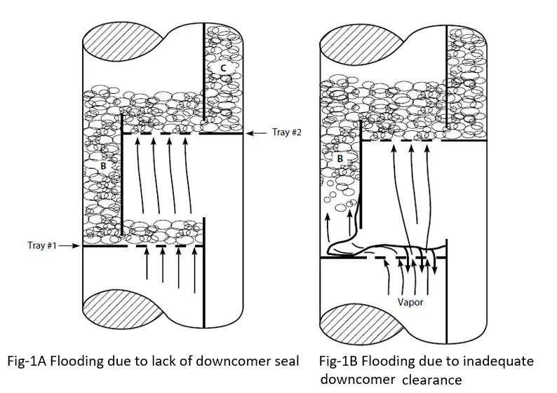
Loss of downcomer seal
As per the figure depicted in Fig.1A, it has been clearly shown that downcomer B is flooding. The reason is the loss of the downcomer seal. The height of the outlet weir is less than the bottom edge of the downcomer from the upper tray. This allows the vapor to flow upwards to downcomer B. The upgoing vapor drives away the downflowing liquid. The vapor pushes the liquid up onto the tray above which is the main reason for flooding.
Inadequate downcomer clearance
The next reason for flooding is inadequate clearance of the downcomer and tray deck which is shown in the figure below (Fig-2). If the bottom edge of the downcomer is too adjacent to the below tray then a higher pressure drop is needed for the liquid to escape from downcomer B onto tray-1 & which causes the liquid level in downcomer B to back up onto tray-2. As a result of that Tray-2 gets flooded. Once tray-2 floods, downcomer C (shown in Fig. 1B) will also back up and flood. This condition will be continued till all the trays and downcomers above downcomer B are flooded. At the same time, all trays below downcomer B will get dry on the loose liquid levels.
Thus, the following rules apply:
- When flooding commences on a tray, all the trays above the flooding point will also be flooded, but trays below that point will get dried up.
- Loss of liquid level in the bottom of the column is an early indication of flooding in a distillation column
- If the downcomer clearance (the distance between the bottom edge of the downcomer and the tray below) is too large, the downcomer becomes unsealed. Then vapor flows up the downcomer, and flooding occurs.
- Liquid starts backing up in the downcomer if the downcomer clearance is too small, and the trays above become flooded.
To calculate the height of liquid in the downcomer, due to liquid flowing through the downcomer clearance:
ΔH = 0.6 × V2
where ΔH = inches of clear liquid backup in the downcomer, due to the head loss under the downcomer V = horizontal component of liquid velocity, in ft/s, as the liquid exits from the downcomer.
To guarantee a proper downcomer seal, the bottom edge of a downcomer should be about 0.5 inches below the top edge of the outlet weir. This dimension should be carefully checked by process personnel when a tower is opened for inspection. It is quite easy for sloppy tray installation to distort this critical factor.
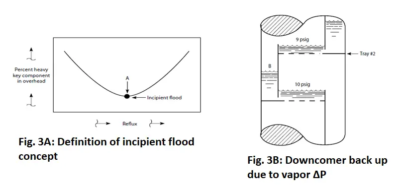
Concept of Incipient Flood
The control of the distillation tower is such that both the pressure and bottom temperature are kept constant. This indicates that the percentage of propane in the bottoms product (butane) is held constant. If the operator increases the reflux flow to the distillation column then the following condition will occur (refer to Fig-2):
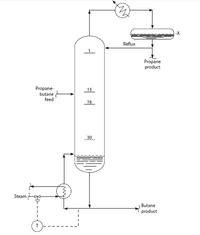
- The top temperature of the distillation tower decreases.
- The weight percent of butane in the overhead product (propane) decreases.
- The bottom temperature of the tower starts to decrease.
- The duty of the reboiler increases to regain the bottom temperature of the distillation tower to its set point.
- The weight flow of vapor and the velocity of the vapor through the tray increase.
- The height of the spray section, or entrainment, between the trays of the distillation tower increases.
As per figure (Fig-3A) Point A is called the incipient flood point, that point in the tower’s operation at which either an increase or a decrease in the reflux rate results in a loss of separation efficiency. One can call this as optimum reflux ratio which would be an alternative description of the incipient flood point.
How to Calculate the Height of Liquid on Tray Deck?
As the liquid height on a tray increases, the height of liquid present in the downcomer that is fed to this tray will increase by the same amount. In addition to that, the excessive liquid present in the downcomer or froth levels causes flooding and loss of efficiency of the tray of the tower. The liquid level on a tray is governed by both of the following factors:
- Weir height
- Crest height
The height of the weir of the trays can be adjusted. It usually adjusts the weir height to between 2’’ and 3’’. This produces a significant depth of liquid on the tray deck to develop effective mass transfer.
The height of the crest is similar to the height of water overflowing a dam or a river.
The formula for the calculation of crest height is,
Crest height = 0.4 (GPM ÷ inch (outlet) weir length)0.67
where crest height = inches of the level of clear liquid overflowing the outlet weir; GPM = gallons (U.S.) per minute of liquid that leaves from the tray.
Total Height of Liquid in the Downcomer
The total height of clear liquid in the downcomer weir is the summation of four factors stated below:
- Liquid exit velocity from the downcomer onto the below tray.
- Height of the Weir.
- Height of the Crest of liquid overflowing the outlet weir.
- The pressure drop of the vapor flowing through the tray above the downcomer.
But in the actual scenario, there is no clear liquid exists either in the downcomer, on the tray itself, or outlet weir. The liquid actually is froth or foam in nature which is called aerated liquid. The factor that compensates aeration effect is 0.5. So 50 percent is often used for many hydrocarbon services.
This signifies that if we calculate a level of clear liquid of 12 inches in the downcomer, then the actual level of foam in the downcomer is 12 inches/(0.50) = 24 inches of foam. If the total height of the downcomer along with the height of the weir is 24 inches, then the height of the foam in the downcomer is 24 inches resulting in downcomer flooding. This is frequently called a liquid flood.
What is Jet Flooding?
Jet flooding occurs when the downcomers and trays consist of froth or foam, there is a quantity of entrained liquid that is lifted above the froth level on the trays of the tower. The driving force that causes this entrainment is the vapor flow through the distillation tower. The height of the spray section of this entrained liquid is governed by two factors:
- The height of the foam resides on the tray
- The velocity of the vapor through the tray
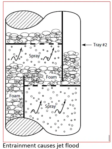
High vapor velocities in conjunction with a high level of foam will cause the height of the spray section to hit the underneath of the upper tray. This results in the mixing of the liquid from a lower tray with the liquid on the upper tray. This back mixing of liquid causes the reduction of separation, mass transfer, or efficiency of the tray of a distillation tower.
If the vapor flows through a tray increases, the froth height in the downcomer draining the tray will increase as well. This will not have any impact on the foam height on the tray deck until the downcomer fills with liquid foam. Then a further increment of vapor flow causes a significant increase in the foam height of the tray of the distillation tower, which increases the height of the spray section. When the height of the spray section from the below tray hits the upper tray, then it is called the incipient flood point or termed the initiation of jet flooding.
Relation between Tower Pressure Drop and Flooding
The relation between the pressure drop of a distillation tower and flooding is important to understand for the prediction and prevention of flooding. The common parameter of process equipment is that smooth operation is reached at neither a very high nor a very low loading. The intermediate equipment load that results in the most efficient operation is called the best efficiency point. For trays of the distillation tower, the incipient flood point corresponds to the best efficiency point. We have correlated this best efficiency point for valve and sieve trays as compared to the measured pressure drops in many distillation towers. We have derived the following formula:
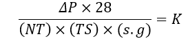
where
- DP = pressure drop across a tray section, psi
- NT = the number of trays
- TS = tray spacing, inches
- s.g. = specific gravity of the clear liquid, at flowing temperatures
On the basis of hundreds of field measurements, we have observed
- K = 0.18 to 0.25: Tray operation is close to its best efficiency point.
- K = 0.35 to 0.40: Entrainment occurs—an increase in reflux ratio significantly reduces tray efficiency.
- K = ≥0.5: Tray is fully engulfed with flood—opening a vent on the overhead vapor line will blow out liquid with the vapor.
- K = 0.10 to 0.12: Low tray efficiency, due to tray deck leaking.
- K = 0.00: There is no liquid level on the tray, and quite likely the trays are lying on the bottom of the column.
What is the turndown ratio?
Turndown is a term that is frequently used with respect to the capacity of the plant. A plant is designed for a particular capacity range that may have to operate at an enhanced or reduced throughput depending upon the changes in the production rate or demands or various factors. It is therefore desirable that the trays should have some degree of flexibility to accommodate variable throughput. Such flexibility is called the turndown ratio is defined as the ratio of the design vapor throughput to the minimum operable throughput.
Sieve trays have a low turndown ratio of about 2. It means sieve try can normally be operated up to 50% of the design vapor throughput. This turndown ratio can be increased by reducing the fractional hole area. Valve trays normally have a turndown ratio of 4 while bubble cap trays have a still larger turndown ratio.
What are Hydraulic Gradient and Multipass Trays?
The difference between the clear liquid heights at the points of the inlet and outlet on a tray is called the ‘hydraulic gradient’ or ‘liquid gradient’ where ‘Gradients’ means the rate of change of a quantity with the position. But the hydraulic gradients are really the ‘difference’ of liquid heights. Basically, this is the requirement of the liquid head to overcome the resistance to liquid flow on the tray.
The value of the hydraulic gradient on a tray should not be more than a fraction of an inch. Preferably, it should be kept within ½ inch. An excessive liquid gradient causes severe malfunctioning of the tray as most of the gas flows through the holes near the middle of the tray and at the outlet weir section (where the ‘effective liquid depth’ on the tray is low) and only a small part of flows through the holes at the liquid inlet side of the tray. Such maldistribution of the gas or the vapor called vapor channeling severely reduces tray efficiency.
So, the hydraulic gradient is a very important operational feature that needs to be checked during tray design. It remains pretty small for the sieve tray. But for the bubble cap tray, it may be significant because the bubble caps offer a larger resistance to liquid flow.
Comparison between several trays
A quantitative comparison of the three frequent trays used in respect of capacity, efficiency, flexibility, cost & other criteria is given in the table below:
| Parameter | Bubble cap tray | Sieve tray | Valve tray |
| Capacity | Moderate | High | High to very high |
| Efficiency | Moderate | High | High |
| Entrainment | High | Moderate | Moderate |
| Pressure drop | High | Moderate | Moderate |
| Turn down | Excellent | About 2 | 4-5 |
| Fouling tendency | High, tends to collect solid | Low | Low to moderate |
| Cost | High | Low | About 20% more than sieve trays |
| Application | Rarely used in new columns | Most applications if turndown is not important | Preferred for high turndown is anticipated |
| Share of market | About 5% | 25% | 70% |
Reference and Further Studies
The following book you can use as a reference and for further studies:
- Troubleshooting Process Operations by Norman Lieberman
Very useful concepts for interview purposes as a chemical engineer
Thanks for sharing
You have to cite Norman Lieberman book since this is just a copy paste