
Pressure is perhaps the most crucial control variable in a distillation column. This variable affects condensation, composition, volatilities, and any process that happens in the column. A distillation column will not achieve smooth operation unless a steady pressure can be sustained.
Normally, column pressure control is integrated with the condensation system. So, condensation control and pressure control need to be considered simultaneously.
General Guidelines for Distillation Column Control
Some general guidelines are given here for pressure and condensation control,
- The overhead stream should enter the reflux drum at a lower velocity so that it prevents disturbances to the surface of the liquid.
- Vapor bypass piping & equalizing line should be self-draining and should consist of no low points where condensate can be accumulated.
- For higher condensing temperatures and a narrow condensing range, condensation on the reflux drum walls may affect condensation and pressure control. Then vapor space insulation of the reflux drum should be considered.
- The pressure-equalizing line should be sized for a minute pressure drop. As a rule of thumb, equalizing the line with 20 percent of the cross-section of the column overhead vapor line is adequate enough to control unbalanced pressure.
Pressure Control in Atmospheric Column
For atmospheric distillation, column pressure is controlled by having the column open to the atmosphere. By varying the airflow in and vent gas out of the column through the column vent. If the air ingression into the system is undesirable, an inert purge is done at the vent.
If the column is open to the atmosphere, the rate of condensation can be often controlled by the level is present in the reflux drum or by the temperature of the reflux drum.
Different Pressure Control Techniques
There are four techniques through which pressure can be controlled in a distillation column.
- Vapor flow variations
- Flooded condensers
- Coolant flow variations
1. Vapor Flow Variations:
If the column has a vapor product the controller directly manipulates the vapor flow (Fig-1a) so that pressure can be controlled. This method is normally used for vacuum columns (Fig-1b), the pressure controller varying the quantity of spillback to the ejector suction. The spill-back control method can also be applied to the pressure columns where the vapor product is compressed. In the schemes shown in Fig-1a & 1b, the rate of condensation is usually manipulated by the accumulator level. For the stacked condenser shown in Fig-1c, condensation rate control is more difficult.
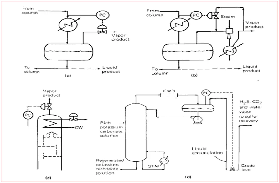
Appropriate piping of the vapor product line is imperative to the success of the above control method. As per Fig-1d, if there is a low leg in which liquid can be accumulated due to entrainment or atmospheric condensation; backpressure can be caused to the column that may interfere with the pressure control.
2. Flooded Condenser:
This pressure-controlling method is one of the best methods for a total condenser system. Some of the condenser surfaces are flooded with liquid always. The flow of condensate from the condenser is directly or indirectly controlled to vary the flooded area. In the flooded area, heat transfer is very low as heat is transferred by sensible heat exchange only. To increase the distillation column pressure, the flow of condensate from the condenser should be less. This low rate enhances the flooded area in the condenser and reduces the surface area exposed to vapor condensation. This results in a reduction of the condensation rate, thereby raising the pressure of the distillation column.
Fig-2a shows a flooded condenser associated with a control valve installed at the condenser outlet. The control valve required is small and should be located as close to the reflux drum as possible to achieve maximum static head. This method is very simple to arrange, linear & maintains the same pressure in the column and reflux drum. So this method is often favored.
The outlet pipe of the condenser may enter the reflux drum either above or below the liquid level. In some cases, it is above the liquid level of the reflux drum so that changes in the level cannot impact the condenser level. Besides, the entry point can be below the liquid level so that cold liquid is introduced at the bottom of the reflux drum. As well as it provides a better seal to the condenser that avoids gas blow-by scenarios through the condenser.
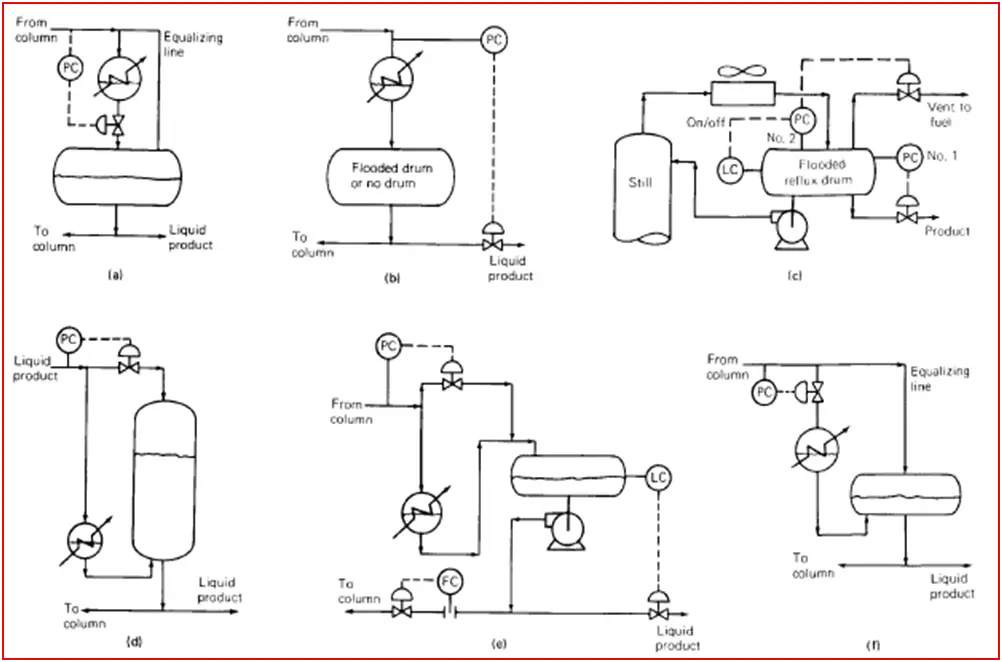
If the sub-cooled liquid is introduced above the liquid level, the vapor above the liquid level may collapse when it meets the liquid resulting in pressure variation.
Pressure-equalizing Line:
The pressure equalizing line plays an important role in this type of control. It helps to maintain a steady pressure through balancing pressure variations. The pressure at the reflux drum may be unsteady without this line. This line should be sized for a minute pressure drop. Normally, the size pressure equalizing line is between ½’’ to 2’’.
Fig-2b illustrates the flooded reflux drum method. This method directly controls the distillate flow. This type of control method usually is avoided for unsteady control unless the product goes to storage.
Fig-2c illustrates an automatic vent system where a secondary pressure controller PC No.2, a level controller, and a control valve are present in the vent line. The setpoint of PC No.2 is normally lower than that of the normal pressure controller (PC No.1). If the drum is full, the level controller keeps PC No.2 tripped off and closes the vent valve. During drum unflooding (due to accumulation of non-condensable) is sensed by a decrease in drum level. The lower activates PC No.2. Since the set point of PC No.2 is closed, helping to build up the drum level. As soon as the drum refills, the level controller trips PC No.2 and closes the vent valve.
Unless the product is sub-cooled & at a significantly higher pressure than storage, it is best to take the product to storage from downstream of the reflux pump. If the product is taken from the drum as per Fig-2c, flashing may occur downstream of the control valve.
Fig-2d shows pressure control by a hot vapor bypass. The condenser is located below the liquid in the drum (horizontal/vertical). The condensate must be sub-cooled so that the liquid surface in the drum is cooler than in the condenser. This causes a difference in vapor pressure large enough to transport condensate from the condenser into the drum.
If the column pressure rises, the pressure controller closes the valve. This reduces the condensation at the drum surface and lowers the drum surface temperature and therefore the drum vapor pressure. It enhances the vapor pressure difference between the condenser and the drum, which in turn forces more liquid out of the condenser and into the drum. This exposes additional condensing surfaces in the condenser and increases the condensation rate.
The advantage of hot vapor bypass arrangement has that advantage of eliminating the need for a condenser support structure easy access for maintenance, a small control valve & fast response. This advantage can translate into major savings in steelwork, platforms, etc.
Correct piping is necessary for the hot vapor bypass line method. Bypass vapor must enter the vapor space of the reflux drum (Fig-1d). The bypass line should be free vapor pockets where liquid can accumulate. If non-condensable are likely, vents are required on the condenser and drum. The condenser vent can be directed to the vapor space of the drum.
In the fig-1e scheme, sub-cooled liquid mixes with dew point vapor. The collapse of vapor takes place at the point of mixing. The rate of vapor collapse varies with the change in subcooling, overhead temperature, and condensation rate. Pressure can fluctuate with the rate of change of the vapor collapse rate. This problem can be ruled out by separating the liquid line from the vapor line and extending the liquid line well below the liquid surface. The vapor line entered the previous inlet.
Fig-2f shows a flooded condenser scheme to that of Fig-2a but with the control valve located at the condenser inlet. This method is inferior compared to Fig-1a. This control method requires a larger control valve, is more difficult to understand and it affects condensation at the lower temperature. The condenser outlet line must enter the reflux drum well below the liquid level. A pressure-equalizing line as in the method shown in Fig-2a is also required. In addition to the above limitations, this method is also prone to liquid hammering if the valve excessively closes.
3. Coolant Flow Variation:
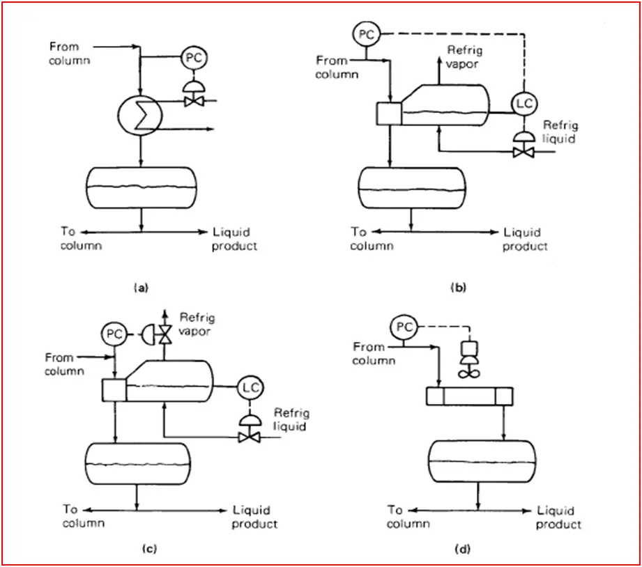
Fig-3a shows an arrangement used with cooling water flow rate variation. This method promotes fouling, and slow response particularly when low-flow operation, when cooling water velocity is low & exit temperature is high. Besides, very low velocity may also lead to freezing during winter. It is recommended to keep the water temperature 120-1300F at the condenser outlet all the time as well as cooling water velocity to be maintained more 3-5 ft/s.
Fig-3b arrangement used with refrigerated condensers. The condenser is a kettle reboiler, boiling refrigerated liquid.
Fig-3c shows an alternative arrangement where the refrigerant level is above the condensing tubes and control column pressure by manipulating a control valve in the refrigerant vapor line. This method is prone to liquid carryover from the condenser, especially if the refrigerant side pressure suddenly drops.
Fig-3d shows a coolant variation arrangement for air condensers. This arrangement is energy-efficient and minimizes fan power consumption.