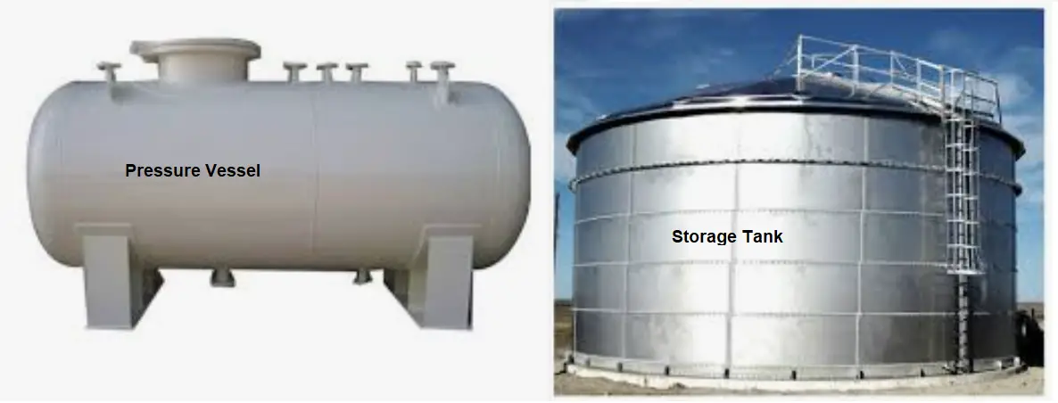
Drums are cylindrical vessels that are used in the process units for a variety of functions. These include intermediate liquid collection, product storage, separation of two different products of different densities, surging, reflux accumulation, and de-aeration. For the above-mentioned functions, the internals required are limited to baffles, demister pads, vortex breakers, distributor piping, and draw-off piping.
Types of drums
Drums are divided into two categories, depending on the orientation of the cylindrical axis. Thus, we have horizontal and vertical drums. Inclined drums are treated as horizontal drums in most cases.
Locating the Horizontal drums
The piping designer is should economize piping interconnections between the drum and its adjacent equipment when locating the drum. The following documents are needed to locate the drum on the plot plan.
- P&ID
- Process Vessel Sketch
- Plot plan
- Piping & Plant Layout Specification.
- The drum is located on the plot plan as per the process sequence dictated by the P&ID.
- Drums can be placed on standalone structures or grouped together with related equipment in an enclosed structure. Adequate space must be provided around the drum for operator movement and maintenance access.
- The drum elevation is fixed by the P&ID. The same may be increased to facilitate piping and equipment layout in consultation with the Process group.
- Keeping the axis of the drum perpendicular to the pipe rack minimizes the space required for locating the drum. Locate close to an access road to reduce maintenance efforts.
- Underground (U/G) drums should be preferably located in open and easily accessible areas. Nothing should be located above the U/G drum as it may be required to be taken out and replaced.
- Underground drums are used to collect gravity-draining liquids like slops. The elevation of the drum should be checked properly as it is supposed to be the lowest point in the collection system. The pipe slope of the underground line, starting point elevation, and the approximate length of piping should be known before the vessel elevation is cleared. The elevation can be lowered below the one specified in the P&ID if the end elevation works out to be below the one given in the P&ID.
- U/G drums generally have vertical pumps and motors mounted on top. Both should be accessible from HPP for plant operation and routine maintenance.
- Drums with mixers and agitators should have a minimum removal space above them equal to the length of the mixer or agitator inside the drum plus one meter.
After the drum has been located on the plot plan, the following jobs are carried out.
- Drum Elevation review
- Nozzle orientation
- Vessel support location planning
- Platform and access requirement
- Support cleat location detailing
- Lifting lugs and earthing lugs location planning
- Finalizing Vessel Name Plate location
Drum Elevation review:
Drum elevation set by the P&ID is the minimum required elevation from the NPSH point of view. This can be increased to suit supporting arrangements.
Nozzle orientation:
The following documents are required for orienting the nozzles.
- Process vessel sketch
- Level co-ordination diagram
- P&ID
- Plant layout specification
- Nozzle summary
- Insulation requirements
- Plot plan
General considerations for locating nozzles:
Generally, the following nozzles are present on all drums.
- Product Inlet
- Product Outlet
- Vapour Outlet
- Drain and Vent
- Instrument Nozzles
- Steam Out Nozzle
- Access Manway
Orienting the nozzles:
While orienting these nozzles the following points are to be considered.
- The product Inlet and Vapour Outlet will be on the top of the drum, as far from each other as possible for proper dis-engagement of liquid and vapor.
- The product Outlet will be on the bottom and as far as possible from the Product Inlet.
- Level Instrument nozzles should be as far from
- the inlet as possible to avoid turbulence at the inlet end.
- Pressure tapping for vapor pressure to be on the top of the drum, near the Vapour outlet.
- Temperature tapping for the liquid temperature to be in the lower liquid region. It is to be ensured that sufficient space is available for the removal of the temperature element. When multiple temperature elements are required, they are best placed at the same elevation along the axis of the drum.
- Steam out connection to be opposite to the access manway and vent.
- The drain is to be located at the lowest point, on the bottom of the drum.
- Inaccessible Instrument nozzles to be located near ladders (location of ladder and Instrument nozzles to be decided concurrently)
- Access manway can be located at the following places, depending on the type of access required into the drum.
- On the top of the drum.
- On the cylindrical portion of the drum (radially or hillside) or at either head for side entry.
- On the bottom of the drum.
- It should be verified that the davit swing area of the manhole cover does not obstruct the movement of maintenance personnel and does not hit any instruments or instrument nozzle connections. The center line of the manhole should be between 600mm to 1000mm (ideally 760mm) from the top of the service elevation of the vessel.
- Special consideration is to be taken for bottom nozzles. They should be located so that they not only clear the saddle support (R/F pads should clear), but they should also clear the concrete or structural support on which the saddle support rest. A minimum of 150mm should be available between the edge of the flange and the edge of the civil support for easy maintenance.
- Gooseneck nozzles should be considered when the piping layout is fixed and requires an elbow immediately at the nozzle.
- In addition to the regular nozzles, vessel boots may be provided for liquid accumulation. This is provided at the bottom of the vessel. The boot should be located as per the guidelines of outlet nozzles. The boot has a draw-off nozzle at the bottom and a minimum of an instrumented nozzle for level measurement. This has to be oriented in conjunction with the upper-level nozzle (on the drum).
Nozzle standouts
Nozzles on the top of the drum should have their flange a minimum of 180mm and a maximum of 1000mm from the TOG of the access platform. Hillside nozzle standouts should be calculated so that there is no clash (hard or soft) between the insulation of the drum and the standpipe. The flange and bolts should also be outside the vessel insulation. Standouts of Nozzles on the heads and on the bottom should be calculated so that the flange and bolts are outside the vessel insulation so that the flange joint is easily accessible for maintenance.
Supporting the Drum:
Horizontal drums are supported on saddles welded to them. These are to be evenly spaced from the center of the drum. Specific requirements on spacing can be passed on to the Mechanical group. For very long drums, additional saddles may be required to prevent the sagging of the drum at the center. This will be indicated by the Mechanical department. The saddle towards the pipe rack is generally made the fixed end and the other support is made the sliding end. This is done in conjunction with piping growth calculation. Slot hole dimensions when provided by vendor drawing should be cross-checked with manual calculation to verify the actual size of the slot required. An additional 5 mm should be added to take care of minor civil dimensional variations.
Preparing the Nozzle Orientation Document:
This document should show the plan, elevation and if required, the side view of the vessel, the proposed location of saddles, and the location of nozzles. Nozzle dimensioning should be from the centerline and one tan line. Nozzle projections should be from the vessel center line. A nozzle summary table indicating the Nozzle number, service, size, rating, flange type, flange face, standout, and remarks is to be included in the drawing.
Miscellaneous Data to be included in Nozzle Orientation Document:
Lifting Lugs
Generally, drums can be lifted with two lugs welded on the top of the vessel. The preferred locations should be marked on the nozzle orientation drawing.
Earthing Lugs
Two earthing lugs, ideally one on each saddle support should be marked on the nozzle orientation drawing.
Name Plate
The nameplate should be located at a prominent location and marked on the nozzle orientation drawing. Care should be taken that the nameplate projects outside the vessel insulation.
Vessel Insulation Clips
Indicate that insulation clips/rods are required for holding the vessel insulating bands.
Platforms and Access Ladders
Platforms are required for operational access to valves, and instruments, and for maintenance. Horizontal drums are to be provided on rectangular platforms.
Calculating the TOG elevation
TOG elevation from the top of the drum = Insulation thickness + 50 mm clearance + Platform member depth (assume 200mm minimum) + 30 mm grating. Round off to the next higher multiple of 10.
Platform sizing
A platform should cover all the nozzles that need access for operations and maintenance. Ideally, a space of 750mm should be provided around 3 sides of a nozzle. This may be lowered at the discretion of the piping lead.
Also, the shape of the platform should allow side entry from the access ladder.
Platforms longer than 6 m should have two access ladders.
Access ladder
An access ladder is provided for entry to equipment platforms. It is also to be utilized for access to instrument connections that are inaccessible from the working level. The ladder should side entry type, wherever possible.
Preparing the Platform Input Document
Platform and Access ladder input is transmitted to Civil via a platform input drawing. This should clearly indicate the TOG, dimensions, and its location w.r.t. the vessel centerline and one tan line. Grating cutout requirements (indicating size, shape, and location) need to be marked on the same drawing.
Supporting Piping from Drums:
Piping should be supported from the vessel or its platform when it is difficult to construct civil support from grade or adjacent structures at the required location. Vessel support may also be taken to take advantage of lower differential thermal growth between vessel and piping, as compared to piping and civil support. A judicious selection of support locations can eliminate the requirement for springs.
Thumb rules for supporting from drums:
- Small loads can be transferred directly to the platform members. These include rest, one-way stops, two ways stop, or hold-down supports and the piping layout should be done accordingly.
- Large loads should be transferred to the vessel shell and the piping layout should be done such that the platform members do not interfere with these independent supports.
- Piping support should not cause any hindrance to the movement of personnel.
- Vessel growth should be considered to check the clash of piping support with any adjacent piping or structure.
Preparing the CPS Input Document
CPS (Civil Pipe Support) input is transmitted to Civil and Mechanical via a CPS input drawing. A sketch clearly indicating the TOS, dimensions, and the CPS location with respect to the vessel center line and one tan line needs to be drawn. A summary table indicating the CPS number, TOS, location of load w.r.t. vessel center line, stress file number, and corresponding node number from the Nozzle cleat load information chart needs to be created. The Nozzle cleat load information chart indicates the various loads acting at the support location under various conditions. It is to be attached along with the CPS input document.


what is the expansion for CPS document