
There are many applications of nitrogen, oxygen, and argon in Industry. Like, Gaseous nitrogen (GAN) is used as a raw material or inert gas, while liquid nitrogen (LIN) is used for refrigeration. Oxygen has various uses in steelmaking and other metals refining and fabrication processes, in chemicals, pharmaceuticals, petroleum processing, glass, and ceramic manufacture, and pulp and paper manufacture. It is also used for environmental protection in municipal and industrial effluent treatment plants and facilities.
As is the case with nitrogen, the noble gas argon is also used for its low reactivity, it can provide higher inertness than nitrogen as well as lower thermal conductivity and improved solubility in water and oils. Also, Argon is more common and cost-effective than the noble gases helium, neon, krypton, and xenon. Nitrogen, oxygen, and argon are almost exclusively separated and recovered from atmospheric air.
Components of Air
Air from the atmosphere is formed from a mix of several gases. The major components are oxygen, nitrogen, and argon, with other gases present in smaller quantities. Water vapor is additionally present in the feed air. The water content of air varies with local ambient conditions considerably based on relative humidity.
The following table (Table – 1) summarised the component of air:
| Elements | Symbol | Composition in Volume |
| Main Elements | ||
| Oxygen | O2 | 20.90% |
| Nitrogen | N2 | 78.10% |
| Argon | Ar | 0.93% |
| Rare Gases | ||
| Helium | He | 5.24 ppm |
| Neon | Ne | 18.18 ppm |
| Krypton | Kr | 1.139 ppm |
| Xenon | Xe | 0.086 ppm |
| Hydrogen | H2 | 0.5 ppm |
| Impurities | ||
| Steam | H2O | Variable |
| Carbon Dioxide | CO2 | 300 to 700 ppm |
| Hydrocarbons | CH4 | 3 to 5 ppm |
| Hydrocarbons | C2+ | <0.5 ppm |
Dominant Cryogenic Air Separation Processes
Three separation methods are predominant for separating constituent gases from the air. They are
- Membrane separation,
- Pressure swing adsorption, and
- Low-temperature rectification, or cryogenic distillation process.
Membrane separation
In this separation process, equipment pumps air into the membrane module and the targeted gases like oxygen and nitrogen are separated based on differences in diffusivity and solubility. For example, oxygen can be separated from the ambient air and collected at the upstream side, and nitrogen at the downstream side.
Pressure swing adsorption
The principle of Pressure Swing Adsorption (PSA) is the amount of adsorbate deposited on the adsorbent increases with increasing pressure. Adsorption increase with increasing pressure and desorption occurs at low pressure. The technique is applied for the adsorptive recovery of O2 and N2 from the air.
Low-temperature rectification i.e. cryogenic air separation process, or cryogenic distillation process (Linde Double Column)
Here, a double column is used for the cryogenic distillation of air. In air separation plants is a combination of two columns used. It was the idea of Dr. Carl von Linde, to build together two columns, as shown in Fig -1.
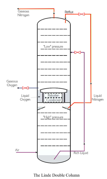
The lower part is a “half” single column with a condenser at the top and an air feed at the bottom whereas the upper part is a single column without a condenser but with a reboiler.
The condenser in the lower column acts as the reboiler for the upper column, those two are thermodynamically attached. Air normally at a temperature that is just above the dew point is fed to the bottom of the lower column. Vapor raises the column to the condenser and forms reflux. “Rich liquid” contains approx. 35-40 % oxygen, is taken out as the bottom product and nitrogen has been taken out as the top product. The bottom product, the rich liquid is then fed to the center part of the upper column for further separation. In this upper column, there is no condenser, but reflux is taken from the pure top product of the lower column.
There is a reboiler at the bottom of the upper column, which is heated from the condensing of nitrogen in the lower column. The upper column can have pure oxygen at the bottom, as oxygen has a higher boiling point than nitrogen.
Comparison of Membrane Separation, Pressure Swing Adsorption, and Cryogenic Distillation Process (Cryogenic rectification)
The three separation techniques have different process properties, and there is a requirement for different ranges of investment and operating costs. The table below characterizes these segments by their production capacity and gas purity. Of course, the numbers given in the table therein are no sharp limits but indicate reasonable application ranges.
| Gas | Capacity (mN3h-1) | Typical purities | Preferred Separation Method | Load range |
| N2 | 1-1000 | <99.5% (including argon) | Membrane | 30-100% |
| N2 | 5-5000 | <99.99% (including argon) | Pressure Swing Adsorption | 30-100% |
| N2 | 200-400000 | any with residual concentrations down to ppb range | Cryogenic rectification | 60-100% |
| O2 | 100-5000 | <95% | Vacuum Pressure Swing Adsorption | 30-100% |
| O2 | 1000-150000 | any with residual concentrations down to ppb range. (O2 content mostly>95%) | Cryogenic rectification | 60-100% |
| Ar | – | – | Cryogenic rectification | – |
Conclusions:
- Oxygen is not recovered with membranes.
- Cryogenic air separation is applied whenever high purity, large quantities, liquid products, or argon is required.
- Membrane and adsorption plants have a high load range in production and can be started and powered up to full production within a few minutes. Especially when the gas consumption fluctuates very high, the flexibility of these types of plants reduces the overcapacity, which has to be provided by design and allows to save energy of manufacturer by fast load matching. A cryogenic plant needs about 2-3 hours to start from the cold condition until the beginning of production of oxygen and nitrogen when in the cold start but from the hot start it takes almost 24 hrs. Membrane and adsorption types of plants are suitable to cover the demands of small and medium-sized gas consumers on-site. This on-site supply competes with the delivery of liquid N2, O2, and Ar by trucks in merchant sites.
Comparison of Energy Consumption in different air separation processes
The operating costs of the separation processes are mainly determined by their energy consumption. Tables -3 and -4 show the specific energy demand for the production of N2 and O2 by the three separation methods. The figures are only guidelines. However, the actual values depend on the detailed process design. Cryogenic air separation requires the smallest work, which, however, is still significantly larger than the minimal separation work needed for a completely reversible process.
| O2 content in nitrogen | 2% | 0.5% | 0.1% | 1 ppm |
| Membrane | 0.43 | 0.65 | ||
| Pressure Swing adsorption | 0.26 | 0.34 | 0.45 | |
| Cryogenic rectification | 0.15-0.25 | |||
| Theoretical minimal separation work | 0.08 |
| O2 purity | 90% | 93% | 99.5% |
| Pressure Swing adsorption | 0.36 | 0.39 | 0.45 |
| Cryogenic rectification | 0.32 | 0.35 | |
| Theoretical minimal separation work | 0.07 |
An Overview of Cryogenic Air Separation Plant
A cryogenic air separation unit (ASU) is a process plant in which air is separated into its component gases by distillation at low temperatures.
The plant comprises an assembly of equipment like distillation columns, heat exchangers, adsorbers, and supporting machinery for compression, expansion, and control of gases and liquids. The component gases are sold and distributed to customers for a wide variety of industrial, medical, and other specialist applications as per requirement. Air separation plants are constructed in different forms depending on what products are produced and the production capacity and purity requirements of the client. Moreover process equipment and machinery from different manufacturers are used as per requirement. However, the basic principles of construction and operating methods for all these different plants are nearly the same.
The design of a cryogenic air separation plant depends on the scale of operations and the nature of the products required from it. While basic principles are always the same, process cycles and flow for each plant can vary significantly based on the requirement.
Air separation plants operate on a range of different process cycles to meet specific customer requirements, in a range of plant capacities extending to the production of over 2,300 tonnes per day of oxygen, with co-production of nitrogen and argon, and sometimes krypton and xenon.
Hazards of Oxygen
Oxygen is a hazardous material in nature and the misoperation of an air separation plant can lead to large energy releases with hazards to personnel and equipment and it needs to be taken care of during detailed engineering of the plant. The operation must always be by specified safe practice guided by the operating procedure mentioned in the operating manual.
Disadvantage of Air Separation Plant: Release of Green House Gas
The air separation process is intrinsically clean and does not generate undesirable side products like the fossil fuel industry. However, because it is energy-intensive, for example, a plant making 2,000 tonnes per day of oxygen consumes around 30 megawatts (MW) of electricity. The major part of power consumption is consumed by the plant’s main machinery like the air feed and product compressors. It indirectly causes the release of a significant quantity of greenhouse gases and uses operating a plant most efficiently, both to minimize cost and reduce the impact on the environment.
Industrial gases are only transported over economically viable distances and since these distances are limited by transport costs and the physical properties of the gases, production facilities are located close to the markets they serve. For higher-value products (eg, argon, helium, specialty gases), it may be economically feasible to locate the plant some distance from the customer.
Location of Cryogenic Air Separation Plant
Typically, air separation sites are located close to large tonnage customers such as steelworks, chemical works, petrochemical plants, oil refineries, and smelters so that the gas may be supplied directly to the customer by pipeline.
Raw Materials for Cryogenic Air Separation Plants
The raw material for a cryogenic air separation plant is air from the atmosphere, called feed air on an air separation site. Most air separation plants produce these three gases (oxygen, nitrogen, and argon) in liquid form. Moreover, some plants produce oxygen and/or nitrogen in gas form for pipe delivery to the customer. Exceptionally some plants produce only gaseous nitrogen called Nitrogen generators.
Products of Cryogenic Air Separation Plant
Product names are LOX Liquid Oxygen, LIN Liquid Nitrogen, LAR Liquid Argon, GOX Gaseous Oxygen, and GAN Gaseous Nitrogen.
Design Consideration of Cryogenic Air Separatin Plant
When a new plant is to be constructed after capacity is finalized and the production capacity and purity determined, the most appropriate process which has the lowest energy consumption and purchase price is selected based on rigorous process cycle simulation. It can be seen that the process equipment and manufacturer can vary widely and it is optimized based on plant life selection, local regulation requirements, etc.
Other components other than nitrogen, argon, and oxygen are in the air:
Dust, Water vapor, Carbon dioxide, Hydrocarbons (eg methane, ethane, propane, and acetylene), Rare gases (helium, neon, krypton, and xenon), and Diverse air contaminants.
Requirements of Pre-Purification System
The Pre purification system is designed to remove water vapor, carbon dioxide, and other potentially unsafe impurities contained in the incoming process air. This is important for the safe operation of the plant as it ensures that the water and carbon dioxide does not enter the cryogenic portion of the plant where they could plug the main vaporizer exchange passages placed in the cryogenic distillation column. Plugged passages can lead to ‘dead-end boiling’ of liquid oxygen creating areas of localized high concentrations of impurities (e.g.; hydrocarbons) within the main vaporizer.
The Pre purification system effectively stops ozone, acetylene, and propylene. It also partially adsorbs propane and ethylene. All of these components are hazardous if found in the cryogenic portion of the plant and will eventually accumulate in the liquid oxygen main vaporizer bath and increase the process risk of explosion in some plants. Pre purification system (PPU) is also known as the Air purification system (APU) and Front End Purification system (FEP).
Basic Principle of Cryogenic Distillation Process
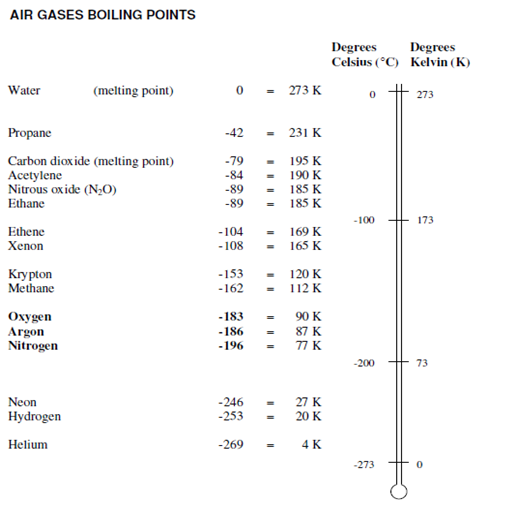
In the cryogenic process, the liquids are close to the boiling point and that heat is leaking in. Table -5 below gives a brief idea of the boiling point of components in the air. These boiling points are measured at atmospheric pressure. The differences in boiling points influence the separation of liquids by distillation.
Process overview of Cryogenic Air Separation Plant
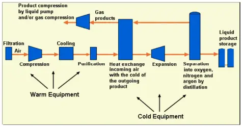
The basic process for large-scale air separation has remained unchanged for decades but the orientation of equipment will change based on process requirements. In this process, the air is compressed, then purified by removing carbon dioxide and water vapor, after that dried and cleaned air is cooled to nearly its liquefaction temperature, and then separated by cryogenic distillation into oxygen, nitrogen, and argon products.
Steps of Cryogenic Air separation
Here are the steps of air gases separation by the cryogenic processes :
– COMPRESSION of air feed lines: it means « make the air enter » the separation unit by bringing it under pressure, and measuring out the flow required to assure the production aimed.
equipment: compressor
– PURIFICATION of air feed lines: to be treated in a cryogenic way, the air has to be purified mostly of water and carbon dioxide (plus some secondary impurities)
equipment: reversible exchangers (abandoned)
alumina + molecular sieve adsorbers: Pre-purification unit
– HEAT EXCHANGE: to permit a continuous functioning of the cryogenic part, the cold recovery of the products getting out is necessary to cool the air feed lines.
equipment: exchangers
– DISTILLATION of air feed lines: to separate it partially into its different components, that is to say, nitrogen, oxygen, and, should this happen, argon.
equipment: distillation columns
– COLD PRODUCTION: to balance the permanent cold losses due to the cold box conception itself and to the liquid productions (if necessary), and for the initial cooling down of the cold box (start).
equipment: expansion turbine, liquefaction cycle, liquid assist
The products can be provided under pressure. The following two processes are adopted for this:
– external compression: products compressors downstream the cold box.
– internal compression: pumping of the products in liquid form and vaporization in the main exchange line.
What is a Cold Box and Why is this required?
The cold equipment needs much insulation to get an acceptable cold loss. So columns, heat exchangers, and parts of the cold production equipment like a turbine, and valves are built in a large tower-like box, the so-called cold box. The cold box is insulated by perlite.
The unique feature of air separation is the great interdependency of the different flows because it is a cryogenic process, in which external media such as cooling water and steam cannot be used. The different products or internal flows are used for boiling and condensing in the columns, like reflux, cooling the incoming air, and for sub-cooling the liquid products based on the process cycle.
Cold nitrogen gas coming out from the cryogenic distillation column is used in the recycling for cold production for liquefaction etc.
A changed gas flow in a stable plant gives a different pressure, and a change of pressure can have a considerable effect on the other flows as their boiling points change with pressure. Also changed temperatures, for example, in a condenser due to a change in pressure will change the rate of heat exchange and therefore change the gas flow in the column which will alter the purity.
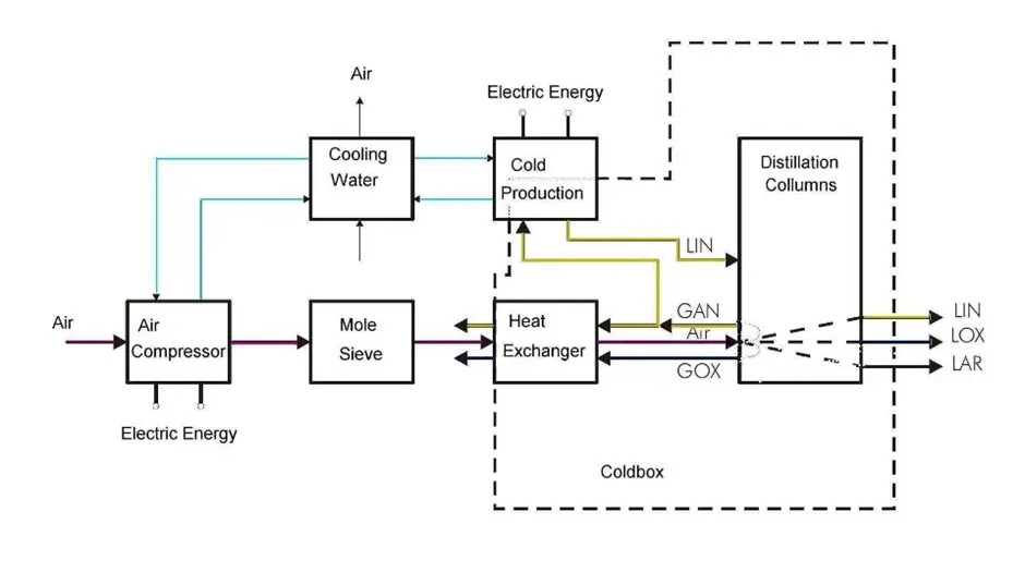
Process Description of Cryogenic Air Separation Unit
The clean, compressed air after pre purification unit enters the cold box and is cooled down almost to its liquefaction temperature, about -170 deg C by out-flowing cold product streams in the main heat exchanger. The air then enters the high–pressure column (hereinafter referred to as the “HP column”) where it is separated by distillation into overhead nitrogen streams and a bottom-rich liquid stream containing about 37% oxygen.
Gaseous nitrogen from the HP column flows into the main vaporizer where it contacts low–pressure liquid oxygen in the sump of the Low-Pressure column (hereinafter referred to as the “LP column”). The liquid oxygen boils (at about -179 deg C ) against condensing high-pressure nitrogen providing reflux in the HP column. The final separation occurs in the LP column, which operates at approximately 1.4 bar a.
Reflux and feed streams are provided by liquid nitrogen and rich liquid from the HP column. These liquids are subcooled against gaseous nitrogen in the liquid sub-cooler before being expanded into the LP column.
The boiling oxygen in the LP column provides the energy necessary to strip nitrogen and argon from the rich liquid stream.
Gaseous oxygen product is taken from the bottom of the LP column and pure nitrogen product from the top. An intermediate waste nitrogen stream, used for reactivation of the adsorber beds, is withdrawn near the top of the LP column. It is typically composed of less than 2% oxygen and contains virtually all the argon that exits the cold box.
Use of LOX Filter
The hydrocarbons not removed from the air by the PPU unit accumulate in the liquid oxygen bath around the main vaporizer. To reduce this hazard, an adsorbent-filled liquid oxygen filter (hereinafter referred to as “LOX filter”) may be provided. Two filters in parallel are installed, with one in the adsorption phase and the other in regeneration.
Function of Turbine in Cryogenic Air Separation
To maintain the proper operating temperatures in the process and to offset the heat leak into the cold box, a cold production unit is required. Normally for a low–pressure gas plant, an expansion turbine is provided as a cold production unit. This machine takes partially warmed nitrogen from the HP column, equal to about 10% of the airflow to the cold box, and through expansion cools it to join the outgoing products. A small flow of high-pressure nitrogen for utility purposes may be further warmed along with the other products in the main heat exchanger. In the more recently designed plants, the turbine operates on a small, clean airflow that has been boosted in pressure by its compressor brake (expander–booster).
Purpose of Liquefier
In the case of large LOX (and LIN) production, a separate liquefier may exist with a permanent liquid assist from the liquefier (for storage, when the liquefier is stopped).
Very detailed description. Must read if want to know more about air separation or cryogenics.
Thank you for Sharing the content in easy understanding way.
Love it I work as process engineer for Linde canada llc , creation of Dr Carl vin linde . You have explained it exactly how are plant is set up . Very good brief .
Thank you for the insight! This will help with my assignment on cryogenic distillation.
– Chemical Engineering Student (UQ)
Thank you. Mr. Anup Kumar Dey for brief fundamentals of cryogenic parameters of Oxygen,nitrogen and argon.Please give some details of piping material and how to select pipinf material or equipment that can avoid dead end boiling.
CAN YOU DESCRIBE THE DEW POINT AND ITS IMPORTANCE IN ASU SYSTEM
How could O2 momentarily intrude into my N2 line coming from the separation plant?
WHAT TYPE OF INSULATION IS REQUIRED IN COMPRESSOR LINES ND WHY IS IT RQUIRED?