A pressure-balanced expansion joint is a type of piping expansion joint designed to absorb thermal expansion while preventing the expansion joint from creating a large pressure-induced force on the piping or equipment.
Why a Pressure-Balanced Expansion Joint is needed
When a pipe contains a pressurized fluid, pressure acting on an ordinary bellows creates an end force: F=P×A
where:
- F = pressure thrust
- P = internal pressure
- A = effective area of the bellows
For high-pressure piping, this force can be very large and would normally have to be resisted by anchors and structural supports.
A pressure-balanced expansion joint uses additional bellows and a balancing arrangement so that the pressure thrust from one bellows is largely cancelled by an opposing pressure thrust.
Types of Pressure-Balanced Expansion Joint
Two types of pressure-balanced expansion joints are widely used in oil and gas industries. They are classified mainly by how the balancing bellows are arranged and what pipe movement they accommodate.
1. Elbow Pressure-Balanced Expansion Joint
This is one of the most common arrangements.
It typically consists of:
- A main flow bellows
- A balancing bellows
- An elbow
- Tie rods/linkages connecting the two bellows
The balancing bellows generates an opposing pressure thrust, so the net pressure force transmitted to the piping is greatly reduced.
Used for: axial thermal movement, especially where an anchor cannot conveniently absorb the pressure thrust.
2. In-Line Pressure-Balanced Expansion Joint
The main and balancing bellows are arranged in line with the pipe.
The pressure thrust from the working bellows is balanced by the pressure thrust from the balancing bellows.
Used for: mainly axial movement in relatively straight piping systems.
A simplified arrangement is:
Pipe → Main Bellows → Balance Bellows → Pipe
Some More Details about In-line Pressure Balanced Expansion Joints
When the expansion joint is installed in a straight pipeline, it is called an In-Line Pressure Balanced Expansion Joint (IPBEJ).
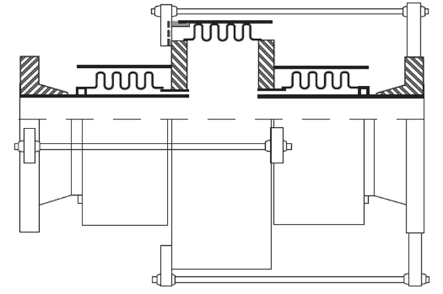
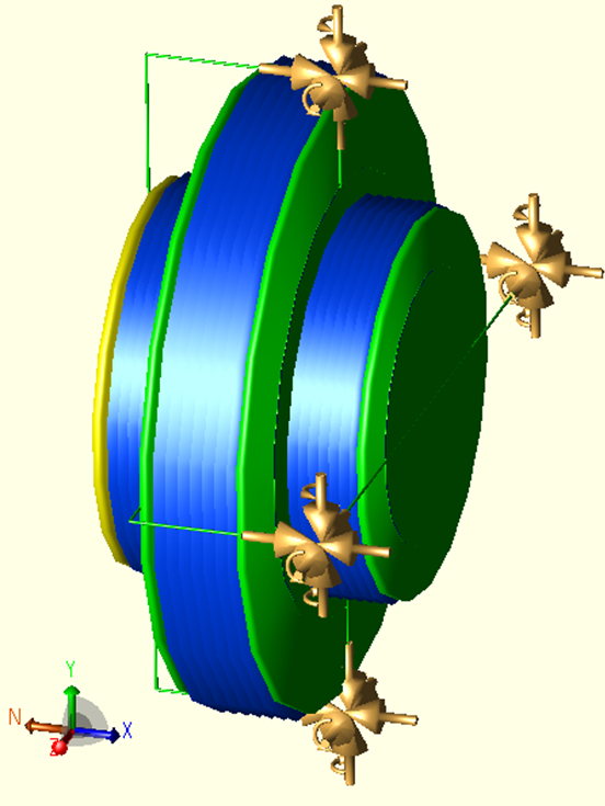
The IPBEJ consists of two smaller bellows placed on either side and one bigger bellows placed in the middle. They are connected by the use of Tie-Rods as shown in Figure 1. So, when the smaller bellows are compressed, the bigger one extends and vice versa.
Since the internal volume is constant, the effective area of the larger bellow is twice the effective area of each smaller bellows (Figure 2):
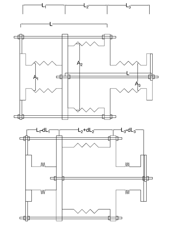
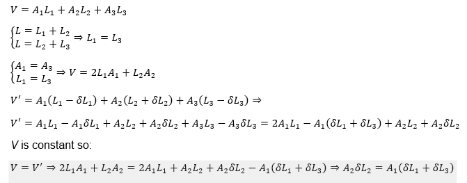
In addition, the length of Tie-Rods is constant, so:
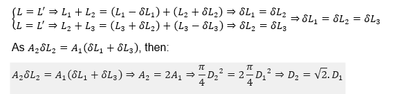
It is concluded that the Pressure Thrust Force (FPT) that either pipe ends receive is zero (Figure 3):
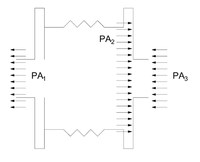
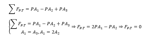
Modelling an In-Line Pressure Balanced Expansion Joint in CAESAR II
Let’s assume that the IPBEJ has 4 Tie-Rods and we want to model the IPBEJ from node number 10 to node number 80 along the +X direction as shown in Figure 4.
Follow the steps below:
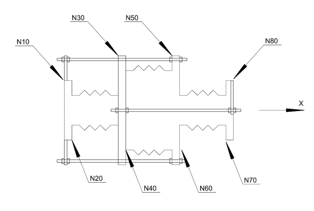
- Element 10 to 20: Rigid element for first flange with total weight divided by 4. Length according to the data sheet along the +X direction.
- Element 20 to 30: Expansion Joint with determined spring rates and effective diameter A1. Length according to the data sheet along the +X direction.
- Element 30 to 40: Rigid element for second flange with total weight divided by 4. Length according to the data sheet along the +X direction.
- Element 40 to 50: Expansion Joint with determined spring rates and effective diameter A2. Length according to the data sheet along the +X direction.
- Element 50 to 60: Rigid element for third flange with total weight divided by 4. Length according to the data sheet along the +X direction.
- Element 60 to 70: Expansion Joint with determined spring rates and effective diameter A1. Length according to the data sheet along the +X direction.
- Element 70 to 80: Rigid element for fourth flange with total weight divided by 4. Length according to the data sheet along the +X direction.
Now the Tie-Rods can be modelled as follows:
- Element 10 to 90: Zero-weight rigid element. Length according to the data sheet along the +Y direction.
- Element 60 to 100: Zero-weight rigid element. Length according to the data sheet along the +Y direction.
- Element 90 to 110: Zero-weight rigid element. Length from node 10 to node 60 along the +X direction.
- Element 10 to 120: Zero-weight rigid element. Length according to the data sheet along the -Y direction.
- Element 60 to 130: Zero-weight rigid element. Length according to the data sheet along the -Y direction.
- Element 120 to 140: Zero-weight rigid element. Length from node 10 to node 60 along the +X direction.
- Element 30 to 150: Zero-weight rigid element. Length according to the data sheet along the +Z direction.
- Element 80 to 160: Zero-weight rigid element. Length according to the data sheet along the +Z direction.
- Element 150 to 170: Zero-weight rigid element. Length from node 30 to node 80 along the +X direction.
- Element 30 to 180: Zero-weight rigid element. Length according to the data sheet along the -Z direction.
- Element 80 to 190: Zero-weight rigid element. Length according to the data sheet along the -Z direction.
- Element 180 to 200: Zero-weight rigid element. Length from node 30 to node 80 along the +X direction.
Notes:
1- The temperature of Tie-Rods shall be at ambient temperature; the OD and THK can be modelled with the OD of the Tie-Rod, and THK can be half of the OD, and the pressure can be set as zero.
2- Weight of the fluid inside the IPBEJ depends on the specified OD and thickness of the elements. Therefore, it is more accurate to determine the OD and THK of bellows as determined in the technical offer and/or data sheet.
Now the restraints of Tie-Rods shall be determined as follows:
- Node 110 to 100: ANC in the X direction, RY, and RZ.
- Node 140 to 130: ANC in the X direction, RY, and RZ.
- Node 170 to 160: ANC in the X direction, RY, and RZ.
- Node 200 to 190: ANC in the X direction, RY, and RZ.
References:
- Pipe Stress Engineering by Peng
- Standards of the Expansion Joint Manufacturers Association, EJMA -9TH Edition
- https://usbellows.com