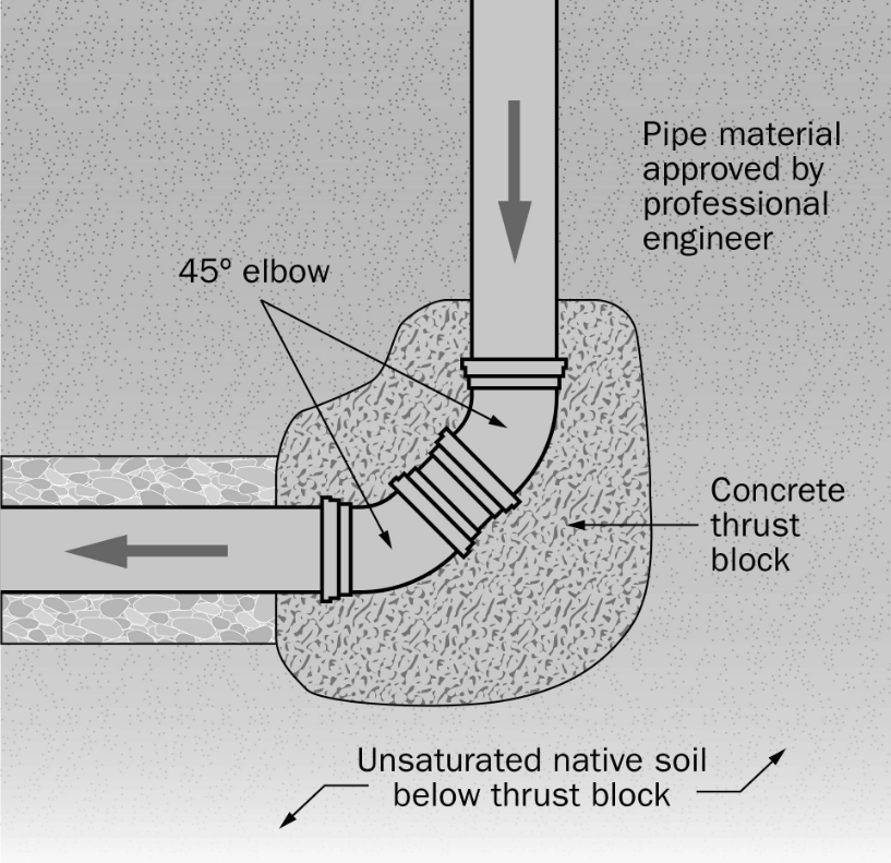
A thrust block in a GRE (Glass Reinforced Epoxy) pipeline system is a concrete support structure designed to resist the forces generated by internal pressure and changes in flow direction. It prevents the pipeline from moving, separating at joints, or becoming damaged due to hydraulic thrust.
Why is a thrust block required?
When fluid flows through a pressurized GRE/GRP pipeline, it generates forces at certain locations, particularly where the flow direction or pipe geometry changes.
Typical locations requiring thrust blocks include:
- Bends: 45° and 90° elbows.
- Tees and branches: Where the flow divides or branches off.
- Reducers: Where the pipe diameter changes.
- Dead ends and end caps: Where the pipeline terminates.
- Valves: Where pressure forces may act on the pipeline, depending on the arrangement.
How does a thrust block work?
A thrust block transfers the hydraulic force from the pipe fitting into the surrounding soil.
For example, when water flows through a 90° bend, the pressure creates an unbalanced force that tends to push the bend away from its position. A concrete thrust block is constructed behind the bend and bears against firm, undisturbed soil to resist that force.
The load path is:
Water pressure → GRE fitting → Thrust block → Surrounding soil
Calculation of Thrust Block Loads for GRE Pipeline Systems
As mentioned earlier, Thrust Blocks (TBs) are structural elements designed to restrict axial movement of pipelines. Consequently, axial elongation resulting from internal pressure and thermal expansion is resisted by a longitudinal force. This resistance acts to compress the pipe back to its original position, and the corresponding reaction force is the load transferred to the thrust block.
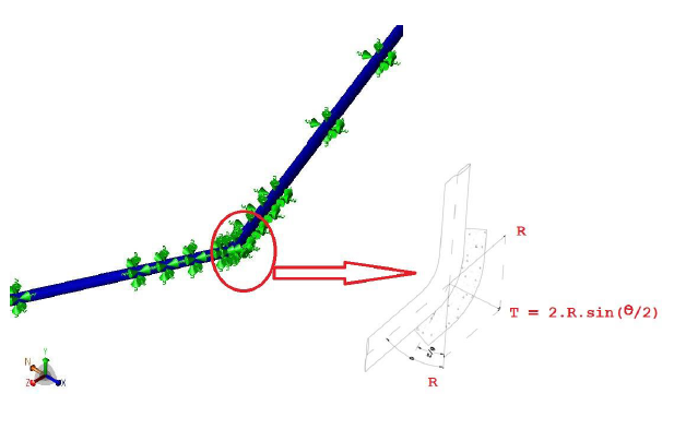
To accurately evaluate loads on a horizontal TB, the analyst must first assess the axial elongation induced by internal pressure and thermal expansion. Subsequently, the required force (R) necessary to produce the same amount of elongation is calculated. The force transferred to the TB depends on both the magnitude of R and elbow angle (θ).
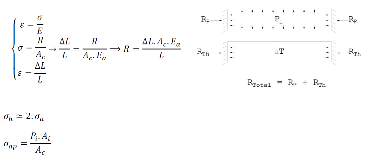
The Axial Elongation due to internal pressure is as follows:

For composite materials such as GRE pipes:
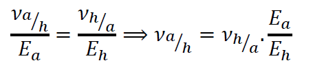
So:

The Axial Elongation due to thermal expansion is as follows:
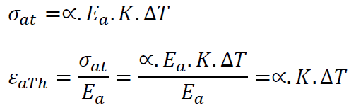
* It is assumed that the thermal expansion in the hoop direction is negligible and does not contribute significantly to the overall deformation of the pipe.
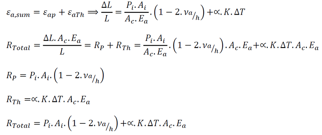
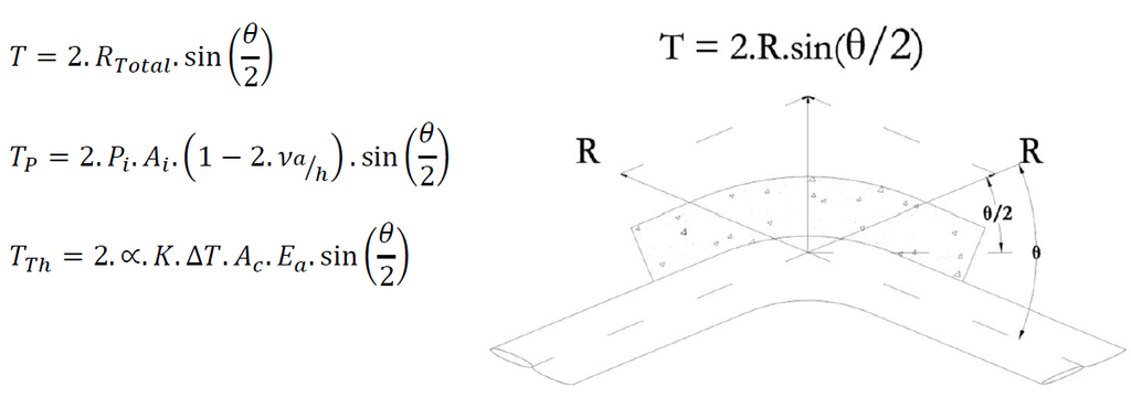
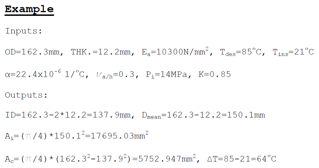
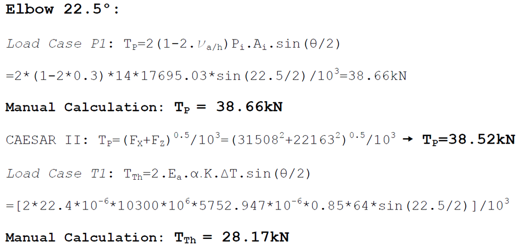
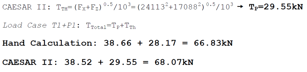
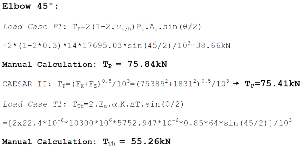
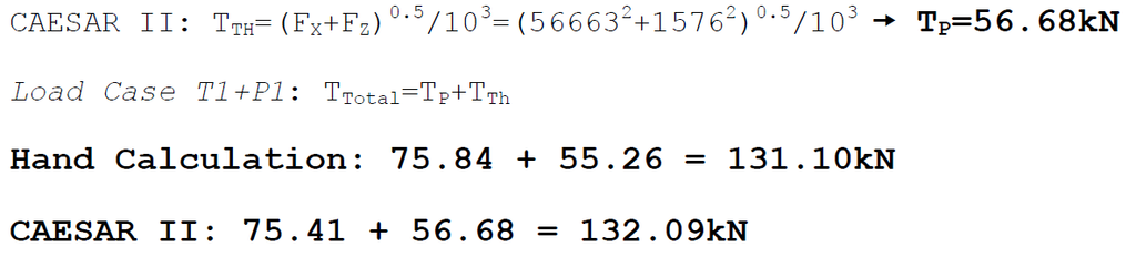
The difference between the manual calculations and the results obtained using CAESAR II is less than 2%, indicating a high level of consistency and validating the accuracy of the analytical approach.
Symbols & Abbreviations
Ac: Cross-sectional area of pipe
Ai: Inner area of pipe
Dmean: Mean diameter of pipe
Ea: Axial elastic modulus of pipe
Eh: Hoop elastic modulus of pipe
ID: Inside diameter of pipe
K: Factor to compensate for the thermal effects of process liquid (BS 7159)
L: Length of the pipeline
OD: Outside diameter of pipe
Pi: Internal pressure
R: Resisting force
RP: Resistance force due to internal pressure
RTh: Resistance force due to thermal expansion
RTotal: Total resistance force
T: Total load on thrust block
TB: Thrust block
Tdes: Design temperature
Tins: Installation temperature
TP: Load on thrust block due to internal pressure
TTh: Load on thrust block due to thermal expansion
THK.: Wall thickness of pipe
α: Thermal expansion coefficient of GRE
ΔL: change in length
ΔT: Change in temperature
εa: Axial elongation
εap: Axial elongation due to internal pressure
εaTh: Axial elongation due to thermal expansion
σ: Stress
σap: Axial stress due to internal pressure
σh: Hoop stress
σat: Axial stress due to thermal expansion
θ: Elbow angle
Va/h: Poisson’s ratio of the strain in the axial direction resulting from a stress in the hoop direction
Vh/a: Poisson’s ratio of the strain in the hoop direction resulting from a stress in the axial direction
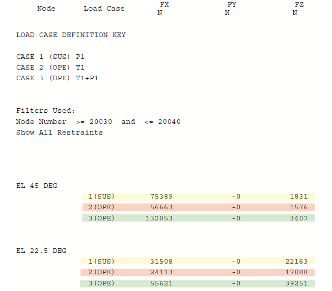
Results of CAESAR II:
Important considerations for GRE pipelines
GRE/FRP pipes differ from steel pipes because they are composite materials and may use bonded, laminated, or elastomeric joint systems. Therefore:
- Do not assume that the pipe joints can resist axial thrust unless the joint system is specifically designed for it.
- Ensure the thrust block bears on suitable soil rather than loose backfill.
- Avoid applying concentrated loads directly to the GRE pipe wall.
- Provide suitable clearance and bearing arrangements around the fitting in accordance with the manufacturer’s requirements.
- Check whether the pipeline design uses concrete thrust blocks, restrained joints, or another engineered thrust-resisting arrangement.
In simple terms: A thrust block is a concrete anchor behind a pipeline fitting that stops water pressure from pushing the fitting or pipe out of position.
References
- AWWA M45: Fiberglass Pipe Design, 4th Edition
- UKOOA: SPECIFICATION AND RECOMMENDED PRACTICE FOR THE USE OF GRP PIPING OFFSHORE
- BS 7159: British Standard Code of practice for Design and construction of glass reinforced plastic (GRP) piping systems for individual plants or sites