
A thrust block is a concrete pipe restraint that prevents the mainline from moving by transferring pipe loads (mainly due to pressure thrust) to a wider load-bearing surface. Usually, thrust blocks are provided for buried pipelines at fittings requiring branching or direction change. The thrust forces generated at the directional changes or tee junctions due to internal pressure thrust are taken care of by these thrust blocks, which prevents the separation of pipe joints on these pipe fitting locations. Thrust blocks are also known as thrust restraints. Thrust blocks are also sometimes referred to as anchor blocks.
What is a Thrust Block?
A thrust block is a concrete structure made to handle the forces from fluid moving through pipes. These forces generated by pressure thrust are directed along the axis of the pipe. The thrust force, if not mitigated/absorbed, can cause significant movement or stress within the pipe system. This could damage the pipe system. The thrust block helps by transferring these forces over a larger area, like the surrounding soil or a concrete base, to keep the pipe stable and in position.
Thrust blocks in piping systems are strategically placed at locations where the direction or diameter of the pipes changes, such as bends, tees, dead ends, and reducers. These points experience significant stress, making thrust blocks crucial for managing this stress.
Why are Thrust Blocks Required? | Purpose of Thrust Blocks
A thrust block’s main purpose is to handle the thrust force and stabilize the pipes, preventing unwanted movement. This helps maintain the system’s integrity and reliability.
Fluids traveling through a piping system under internal pressure exert a thrust force at all bends, tee junctions, reducers, and stop ends. The magnitude of these forces is usually so high that they can easily weaken the joints and even cause leakage or failure of the piping/pipeline system. With an increase in the piping size, these forces increase further. Installation of a thrust anchor block partially absorbs that pressure thrust force and the remaining is transferred to the surrounding soil.
However, note that anchor thrust blocks are rarely used for steel pipes, as the thickness of welded pipes is normally sufficient to prevent joint separation. However, thrust blocks are quite common in ductile iron, GRP/FRP, PE/HPDE, and PVC piping systems.
How Thrust Blocks Work | Thrust Block Working
Thrust blocks or anchor blocks are key parts of unrestrained piping systems. They manage the forces created by moving fluids in the pipes. These forces are strongest where the pipe changes direction, like at bends, or where the pipe ends, such as at caps or valves. Here’s how they work:
Functionality of Thrust Anchor Blocks
Counteracting Forces:
When fluid moves through a pipe, especially under high pressure, it exerts a force in the flow direction. At a bend or change in direction, it generates a reaction force in the opposite direction to fluid flow. At the elbow center, both these forces add up and can cause the pipe to move or shift. A thrust block absorbs these forces and keeps the pipe in place, preventing joint failures or leaks.
Force Distribution:
Thrust blocks spread the forces over a larger area. Instead of the pipe handling all the stress, which could cause damage, the thrust block distributes the force across a wider area, often into the surrounding soil or concrete.
Thrust Block Design
As already mentioned, a thrust block is a large concrete block. It has to be sized properly so that the thrust block is capable of withstanding the pressure thrust force. Even though thrust blocks are specifically designed to absorb pressure thrust force, they should be designed to withstand thermal forces as well. Sometimes the thermal load can be more than the pressure thrust load. So, it is suggested to find out both thermal and pressure loads and consider the maximum force value for the calculation of the thrust block design. So, to size a thrust block, the first requirement is the thrust force.
Thrust Force Calculation for Anchor Thrust Block Design
The raw formula for the calculation of thrust force is Pressure multiplied by the internal cross-sectional area of the pipe. However, depending on various pipe configurations, this formula requires modification. The following image (Fig. 1) provides some typical thrust force calculation formulas for ductile iron pipes (Reference: Ductile Iron Pipe Research Association)
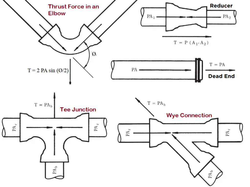
- Thrust Force on an Elbow or Bend: To Calculate the design thrust force or resultant force for bends the following formula can be used. Thrust force, F = 2 P A sin (ϕ/ 2) Where: P = design pressure, A = cross-sectional area of the pipe, and ϕ = angle of the bend.
- Thrust force on Plugs or Caps: The Thrust force in a plug or cap is equal to the design pressure (P) times the cross-sectional area (A) of the pipe. (Thrust force, F = P A).
- Thrust force for Tee connections: The thrust force generated in a Tee connection is calculated as F=P Ab. Where P=internal design pressure and Ab= cross-sectional area of the branch pipe.
- Thrust force calculation of Pipe reducers: The design thrust force for piping reducers/expanders is equal to the design pressure (P) times the difference of the cross-sectional areas of the large (A1) and small end (A2) sizes of the reducer. Hence, thrust restraint force, F = P (A1 − A2)
The thermal load can be directly taken from any stress analysis software like Caesar II, Start-Prof, Rohr-II, Caepipe, or Autopipe.
Once thrust force (Let’s assume the calculated value of thrust force is F) is known, we have to calculate the area required to withstand that thrust force. The area can be calculated by knowing the soil properties where the thrust restraint will be installed. The required soil parameter is the bearing pressure (Let’s assume it to be Pb) of the soil. So, the minimum area required (A) can be easily calculated by dividing the thrust force by soil bearing pressure. Hence, the minimum required area, A=F/Pb. This minimum area should be multiplied by a factor of safety (usually 1.5) to get the actual area.
Once the minimum required area is known, the thrust block geometry can be designed after knowing the type of pipe fitting where the thrust block will be installed. So, the term “thrust block calculation” means the calculation of thrust force and the required area for a thrust block that is sufficient to absorb the thrust force.
Thrust Block Construction
Concrete is the most popular element for constructing thrust blocks. Concrete material is strong and dense enough to arrest the generated thrust forces. The design of these blocks—both in size and shape—depends on several key factors:
- Pipe Diameter and Material: The dimensions and the material of the pipe influence the thrust block’s requirements.
- Fluid Pressure and Velocity: Higher pressure and faster-moving fluids necessitate larger or more robust thrust blocks.
- Pipe Bend Angles: The configuration of pipe bends affects how forces are distributed, impacting thrust block design.
- Soil Conditions: The type of soil surrounding the pipe must support the thrust block adequately to prevent shifting or compression.
For thrust blocks to perform their function effectively, they must interact properly with the surrounding environment.
- Soil: The soil must support the thrust block without excessive compression or shifting. Often, soil testing is conducted to determine the correct design and sizing.
- Concrete and Reinforcement: To enhance their durability, concrete thrust blocks are typically reinforced with steel bars or mesh, which helps them withstand the forces without cracking or deteriorating.
Factors Affecting the Size of a Thrust Block
So, as specified above, there are four parameters required for sizing a thrust block. Those are:
- Maximum Internal pressure to calculate thrust force
- Pipe Size to calculate pipe cross-sectional area for calculating thrust force.
- Soil bearing load to find out the area required for the thrust block and
- Type of fitting (& Degree of angle in case of bends) to define the geometry of the thrust block
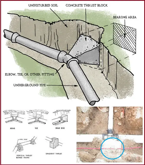
Fig. 2 below are some images of typical thrust blocks.
Key Components of a Thrust Block and Their Roles
Thrust blocks are essential elements in piping systems designed to manage and distribute the forces generated by fluid flow. Understanding the thrust block component details that make up a thrust block and their functions is crucial for ensuring its effectiveness and durability. Now we will describe the primary components and their roles in the construction of thrust blocks.
Concrete
Concrete serves as the primary material for thrust blocks due to its impressive strength and durability. It is capable of absorbing and redistributing large forces, which helps prevent pipe displacement or damage under pressure.
- Mix Composition: The concrete used in thrust blocks typically includes a carefully measured blend of cement, water, aggregates, and sometimes additives. These elements are combined to enhance strength, reduce curing time, and improve overall durability.
- Curing Process: Achieving the desired strength and longevity of the concrete requires proper curing. This process involves maintaining the right moisture levels and temperature until the concrete reaches its optimal strength.
Reinforcement
To bolster the structural integrity of concrete thrust blocks, reinforcement is often used. This reinforcement generally comes in the form of steel rebar or wire mesh.
- Steel Rebar: Reinforcing bars are embedded within the concrete to resist tensile and shear stresses. The specific layout and sizing of rebar are determined based on expected loads and environmental conditions.
- Wire Mesh: For smaller or less critical thrust blocks, wire mesh may be employed. It helps evenly distribute stresses and mitigate the risk of cracking.
Formwork
Formwork refers to the molds or frames used to shape the concrete as it sets. The design and material of the formwork are crucial for ensuring that the thrust block achieves its intended shape and effectiveness.
- Materials: Formwork can be constructed from wood, metal, or plastic, depending on the project’s requirements and whether it will be reused.
- Design: The formwork must be designed to handle the anticipated forces and accommodate the pipe and soil interface. It should also be easily removable to avoid damaging the set concrete.
Interface Material
Interface materials are placed between the pipe and the concrete to protect the pipe from potential damage due to direct contact with the concrete. They help distribute loads and accommodate minor movements and vibrations.
- Rubber or Neoprene Pads: These materials are commonly used to cushion the pipe and reduce stress concentration at contact points.
- Sand or Gravel: In some designs, a layer of compacted sand or gravel is used around the pipe before pouring concrete. This layer provides a softer bedding that helps absorb some of the forces.
Protective Coatings
To extend the lifespan of thrust blocks, particularly in harsh environments, protective coatings can be applied to the concrete.
- Waterproofing Agents: These coatings prevent water ingress, which can cause freeze-thaw damage and corrosion of reinforcements.
- Chemical Resistant Coatings: In industrial settings where chemical exposure is a concern, coatings resistant to chemicals protect both the concrete and reinforcement from deterioration.
Expansion Joints
In scenarios where temperature variations are significant or thrust blocks are large, expansion joints can be incorporated. These joints allow for the expansion and contraction of both the concrete and the pipe, preventing damage and undue stress.
- Materials: Expansion joints are usually made from compressible materials such as fiberboard or rubber.
- Placement: They are strategically positioned within the thrust block and around the piping to facilitate movement while maintaining structural integrity.
Types of Thrust Blocks
Based on specific applications and environmental conditions, Thrust blocks are designed from different materials. Depending on the constituent material, the most common types of thrust blocks are discussed below:
1. Concrete Thrust Blocks
Concrete thrust blocks are the most prevalent type due to their durability, strength, and versatility. Concrete’s ability to absorb and distribute large forces makes it well-suited for a wide range of applications.
- Pre-cast Concrete Blocks: Manufactured in a controlled environment, pre-cast concrete blocks ensure consistent quality and are typically used in standard applications where forces are predictable and uniform. Their pre-made nature allows for quick installation and reliable performance.
- Poured-in-Place Concrete Blocks: For more complex or customized applications, poured-in-place concrete blocks are ideal. This method allows for a tailored fit, adapting to specific site conditions and pipe configurations. It ensures that the thrust block integrates seamlessly with the surrounding environment.
2. Steel Thrust Blocks
Steel thrust blocks are less common but offer advantages in certain situations. They are particularly useful in applications where a high strength-to-weight ratio is critical, such as in elevated or suspended piping systems.
- Steel Plate Blocks: These blocks are constructed from thick steel plates welded together to form a robust anchor for pipes. They are often employed in industrial settings, where high-pressure pipes require substantial support.
- Steel Rods or Cable Systems: In some scenarios, steel rods or cables are used to anchor pipes to stable structures like bedrock or building foundations. This approach provides a secure attachment in environments where traditional concrete might not be practical.
3. Composite Material Thrust Blocks
Composite material thrust blocks are gaining popularity due to their advanced properties, which cater to specific needs such as weight reduction or enhanced environmental resistance.
- Fiberglass: Renowned for its resistance to corrosion and lightweight nature, fiberglass thrust blocks are used in harsh environments like chemical processing facilities or marine applications. Their durability in aggressive conditions makes them a valuable choice.
- Polymer Concrete: Combining the strength of traditional concrete with the advantages of plastics, polymer concrete is an excellent choice for areas with acidic soils or high moisture levels. It offers a balance of strength, light-weight, and resistance to environmental factors.
What is a thrust block on a pipeline?
Thrust blocks in a pipeline refer to the concrete blocks provided in buried pipelines for preventing movement and absorbing thrust forces. For large buried pipelines, the pressure thrust force becomes too large and is usually exerted on elbows and tees. Thrust clocks are therefore added in those regions to avoid the failure of piping components.
How does thrust block work?
Thrust blocks are sized to have a larger bearing area, which transfers the thrust force from pipe fittings to the soil and thereby safeguarding from joint failures.
Where are thrust blocks needed?
Conventionally, thrust blocks are needed in underground pipeline directional changes. So, in all the fittings like elbows, wyes, Tees, and Pipe Caps, wherever the pipeline changes its direction.
What is the Difference Between an Anchor Block and a Thrust Block?
The terms “anchor block” and “thrust block” are used synonymously in most of the cases as the major function is almost similar. Both thrust block and anchor block in pipelines serve as anchors and fix the pipeline at location. However, the actual difference arises in the use of proper application. The main aim of thrust blocks is to absorb and distribute pressure thrusts whereas the main aim of anchor blocks is to fix the pipeline in position. Even though at the end both serves the same purpose. Other differences between a thrust block and an anchor block are
- Thrust blocks are installed only in changes in pipeline directions but anchor blocks can be installed in line with pipe fittings, in between flanges, tie-in connection with dissimilar materials, etc.
- Thrust blocks are usually cast with a small part of the pipeline fitting inside it. However, the anchor block usually cast all around (360 Degrees) to encapsulate the full fitting or pipe part.
Do you know how to calculate the thrust block geometry
yes
thanks for your blog.
i have one doubt how can we get thermal loads acting in tee and bend …shall we put anchor or directly from the restrain report of Caesar II
Yes… thrust blocks are basically anchors on pipes…
For welded pipe normally thrust block is not provided. We have to prove with calculation that thrust force is taken by welded pipe. thrust force I have calculated Thrust force = 2PA sin angle/2. After wards how to prove that this thrust force is taken by welded pipe. The thrust force comes to around 35T, 610mm OD and 8mm thick pipe for 8.82 bar. Please help. I have to submit the calculation. How this so much of force is distributed
Either you can put ‘ANC’ or define the Displacement ‘D1’ as 0 in all directions, at the center of each Bend or Tee. One of the advantages of defining Displacements as 0 is that it will remain intact even after generating the Buried Model, unlike ANC where you have redefine in Buried Model. Also, you have to add D1 in applicable Load Cases, if you go for 2nd apprach as mentioned above.
Hi, may I know how do we determine the maximum internal pressure to calculate thrust force?
Internal pressure can be obtained from the pump calculation. The maximum possible pressure for a system with a centrifugal pump is the pump shut off head.
Does this maximum internal pressure provided by the centrifugal pump system proportional to the head from a reservoir in a gravity flow pipeline?
if we have elbow in potable water system the pipe size 2.5 inch operation pressure 3bar in this case the thrust block required ?
if i have Two DI pipes , 600mm & 800mm DIA , difference gap is only 1.4Meter , we will fix A Equal Tee 600x600mm on the 600pipe , behind far1.4M is the 800mm DIA , how to fix the required thrust block.
In the end, for what pipe sizes are thurst blocks required? Only for the mains, correct? For the service lines, like 63mm, there should or should not be a thrust block at HDPE-VALVE connection?
Thank you. Very resourceful.
I am looking to do a seminar on thrust block theory, application, and design. Would you be willing to teach some of my engineers?
I wonder if the GRE lamination joints need a thrust block or not??