
Modeling Fired Heater Piping Connection is a bit tricky as the pipe is not welded to a fired heater shell similar to ordinary equipment. The heater has a hole, the pipe runs through that hole inside the heater body.
There are two techniques for modeling fired heater piping connection:
- First method: Use an anchor at the point where the piping goes inside the heater. The heater vendor must provide the allowable loads for this anchor point. Or the API 560 code may be used
- Second Method: Model the whole or part of the furnace coil that is inside the heater. The vendor should provide allowable displacements at the point where the pipe goes inside the heater (+dx, -dx, +dy, -dy, +dz, -dz). Usually, it’s the gap values between the pipe and heater shell
You can choose one of these two methods.
First Method – Allowable Loads
The first method is very conservative. The loads on the fired heater usually are very huge, but allowable loads are very small and can’t be met.
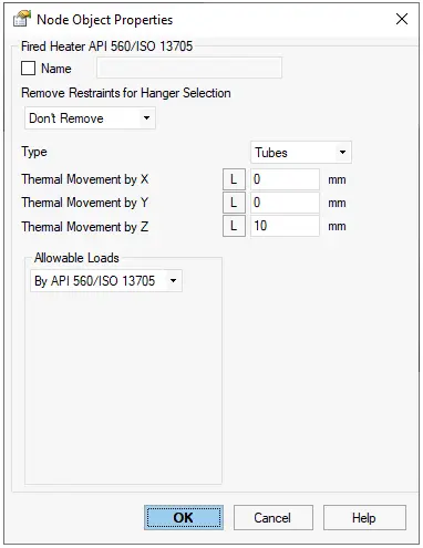
In START-PROF software the “Fired Heater” Object can be used.
Second Method – Allowable Displacements
Using the second method it is easier to satisfy the vendor requirements. There’s no need to model the whole furnace coil, just 3-4 U-Tubes are enough.
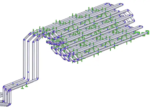
The supports in the furnace coil should be modeled correctly.
The following conditions should be met:
- Pipe displacements at the point where pipe hoes inside the heater should be less than the vendor’s allowable
- All stresses both in the pipe and in the furnace coil should be less than allowable according to the selected code
- Loads on the furnace coil supports should be less than allowable
How should the tube supports inside furnace be modelled? Shall we consider any gap for guides? Note that they are supported by tube sheets in a circular seat. Moreover, nonlinear effect force us to remove most of frictions on tube supports which greatly affect the results. Final question, do you recommend adding an anchor at midpoint of tubes, since the expansion is normally symmetric.
Thank you so much in advance for your useful posts.
Heat transfer takes through hot gases surrounding tube. Do you feel if we need to take any Bourdon effect on it we can see thermal gradient through wall thickness. If we need to take it then, how to quantify the temperature delta to be considered while considering bourdon effect. Any approach for this?