
Shell and Tube heat exchangers are frequently used in Oil & Gas, Power plants, Refineries, and Chemical and Petrochemical industries. As piping systems connected to such equipment are considered Critical, piping stress engineers need to model it quite frequently. But sometimes, specifically for new stress engineers, the modeling steps seem to be very difficult. In this article, I will try to illustrate the modeling considerations in caesar II.
Two types of shell and tube heat exchangers are used in industrial applications.
- Heat exchanger without expansion bellow and
- Heat exchanger with an expansion bellow in the shell.
The thermal profiling considerations i.e, the temperature distribution during Caesar II modeling is different in both cases.
Inputs required for Modeling
Before modeling the equipment the following details need to be collected.
- Equipment GA drawing with all dimensions.
- Fixed and Sliding saddles.
- Shell side inlet and outlet design parameters.
- Channel or tube side inlet and outlet design parameters.
Modeling of the Heat exchanger without expansion bellow
Caesar II modeling of heat exchangers that do not have an expansion bellow is quite easy. Better engineering practice is to model the equipment as a rigid body. Refer to Fig. 1 and the Table below that simultaneously for modeling the elements as shown.
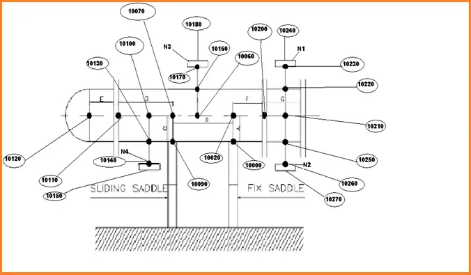
| Region | Node No | OD & Thickness | Process Parameters | Temperature | Material | Length | Remark |
| Fixed Saddle (A) | 10000 to 10020 | Shell | Shell | ( Tis + Tos ) /2 | Shell | Shell OD/2 i.e Length A | Fixed Anchor at node 10000 |
| Part of Shell in between Fixed and Sliding saddle (B) | 10020 to 10070 | Shell | Shell | ( Tis + Tos ) /2 | Shell | Length B from equipment GA | |
| Sliding saddle (C) | 10070 to 10090 | Shell | Shell | ( Tis + Tos ) /2 | Shell | Shell OD/2 i.e Length C | Hold Down + Guide at node 10090 |
| Shell part after sliding Saddle (D) | 10070-10110 | Shell | Shell | ( Tis + Tos ) /2 | Shell | Length D from Equipment GA | |
| Channel Length (E) | 10110-10120 | Channel | Tube | ( Tit + Tot ) /2 | Channel | Length E | |
| Remaining Shell after Fixed Saddle (F) | 10020-10200 | Shell | Shell | ( Tis + Tos ) /2 | Shell | Length F from GA | |
| Channel Length (G) | 10200-10210 | Channel | Tube | ( Tit + Tot ) /2 | Channel | Length G |
Here
- Tis = shell inlet temperature
- Tos = shell outlet temperature
- Tit = tube inlet temperature
- Tot = tube outlet temperature
Modeling the Equipment Nozzle Connection
Modeling steps are shown for Nozzle N1
- At first, model a rigid element from node 10210 to 10219, other parameters will same as the region (i.e, channel region G in this case). Then put the anchor at node 10220 and connecting node 10219.
- Then model from 10220 to 10230 as the pipe element with all mechanical and physical properties of the nozzle (refer to mechanical datasheet)
- Then model the element 10230 to 10240 as a flange element with all mechanical and physical properties of the flange (refer to mechanical datasheet).
All other nozzle modeling procedures will be similar to nozzle N1 modeling.
From node 10240 onwards connected piping can be modeled.
Modeling of the Heat exchanger with an expansion bellow in the shell
Refer to Fig. 2 and Table below that simultaneously to model the elements as shown.
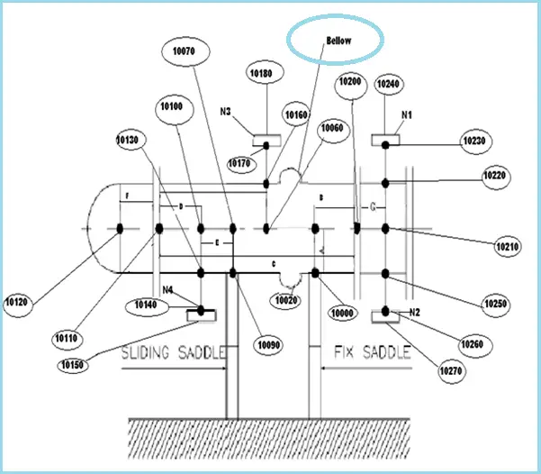
| Region | Node No | OD & Thickness | Process Parameters | Temperature | Material | Length | Remark |
| Fixed Saddle (A) | 10000 to 10020 | Shell | Shell | ( Tis + Tos ) /2 | Shell | Shell OD/2 i.e Length A | Fixed Anchor at node 10000 |
| Part of Shell in between Fixed Saddle and Channel (B) | 10020 to 10200 | Shell | Shell | ( Tis + Tos ) /2 | Shell | Length B from equipment GA | |
| Complete Shell Length (C) | 10200 to 10110 | Shell | Tube | ( Tit + Tot ) /2 | Tube | Length C from GA | |
| Shell Part in between Nozzle N4 and channel (D) | 10110-10100 | Shell | Shell | ( Tis + Tos ) /2 | Shell | Length D from Equipment GA | |
| Shell Part in between Nozzle N4 and sliding saddle (E) | 10100-10070 | Shell | Shell | ( Tis + Tos ) /2 | Shell | Length E from GA | |
| Sliding Saddle | 10070-10090 | Shell | Shell | ( Tis + Tos ) /2 | Shell | Shell OD/2 | Hold Down and Guide at node 10090 |
| Channel part (F) | 10110-10120 | Channel | Tube | ( Tit + Tot ) /2 | Channel | Length F from GA | |
| Channel part (G) | 10200-10210 | Channel | Tube | ( Tit + Tot ) /2 | Channel | Length G from GA |
Nozzle is to be modeled in the same way as shown for the above Heat exchanger.
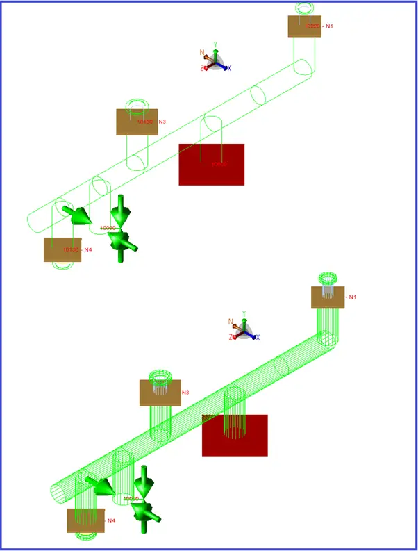
Few companies model the Saddle/Skirt part from the bottom of the shell. In that case rigid element is to be modeled from nodes 10000 and 10090 with saddle length as per GA. (Different saddle temperatures are to be considered for these elements, However, shell material, OD, and thickness can be considered for modeling this part.). In such a situation, the fixed anchor and hold down+guide supports need to be considered at the bottom of the saddle.
A sample model is shown in Fig. 3 below.
Few more Exchanger related resources for You..
Basics of Shell and Tube Heat Exchangers: A brief presentation
An article on Plate Heat Exchanger with Steam
A typical Check List for Reviewing of Shell & Tube Heat Exchanger Drawings
A brief presentation on Air Cooled Heat Exchangers
Basic Considerations for Equipment and Piping Layout of Air Cooled Heat Exchanger Piping
Reboiler Exchanger and System Type Selection
where is the bellow when modelling the heat exchanger of expansion bellow in shell?
where is the expansion joint in the second modeling???
and thanks for your guide.