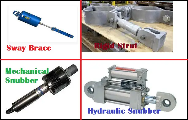
A sway brace is a mechanical device used in process and power plants to reduce the vibration tendency by absorbing shock loadings. They contain a spring-loaded mechanism that provides opposing force for dynamic events (vibration, sway) in both a tension and compression mode while allowing pipe thermal movement. So whenever vibration or any dynamic event occurs the spring force of the sway brace acts in the opposite direction and brings the system back to normal operating condition by absorbing that vibrational force.
In this article, I will explain the procedure for modeling Sway Braces in Caesar II.
Sway braces are spring (pre-loaded) loaded units to limit the swaying or vibration induced by external forces by applying an opposing force on the pipe. The sway brace is simulated by the use of bi-linear restraint available in CAESAR II. It will be discussed in the following section.
Modeling Sway Brace in Caesar II
The steps involved in modeling a sway brace in Caesar are as follows:
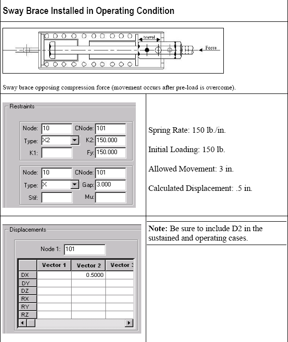
- Select the sway brace from the catalog depending on the given pipe’s nominal diameter or depending on the force calculated to restrain the pipework. (Fig. SB45 as per the C&P catalog reproduced in Fig. 1)
2. Mark a node (Node 10-Fig.2) at the location in the piping system where the sway brace will be installed. Run Caesar analysis and note down the displacement of the point in the specified direction from cold to operating condition. For the sake of example, let’s assume that CAESAR II calculated displacement from cold to operating position is 0.5 inch in +X direction.
3. Now in the CAESAR II input spreadsheet (See Fig. 2) check the restraints box and define bi-linear restraint (X2 for the assumed case) at Node 10 with C-Node at 101. Here, K1 is the initial stiffness of a bi-linear restraint. Do not enter anything on this cell as the restraint is assumed to be rigid. The value of Fy is to be obtained from the catalog. Where K2= Post yield stiffness of a bilinear restraint. When the load on the support restraint exceeds Fy then the stiffness on the support restraint changes from K1 to K2. Fy = Yield Load. If the load on the support restraint is less than “Fy” then the initial stiffness K1 is used. If the load on the support restraint is greater than “Fy” then the second stiffness ” K2” is used.
4. Define restraint X at node 10 with C-Node at 101. Provide a gap of 3 inches (=distance the sway brace is able to move in both positive and negative direction before it gets locked/ become fully rigid depending on manufacturer= 3 inches as per C&P catalog)
5. Check the displacement box and define the displacement for Node 101. It is the displacement for node 10 as noted earlier (0.5 inches in the X direction, leaving other cells i.e., DY, DZ, RX, RY, RZ blank.).
6. Add D2 in sustained and operating load cases. Now run the analysis to obtain results.
Few more Resources for You…
Brief Description of Sway Brace, Strut and Snubber (Dynamic Restraints)
Modeling of Sway Braces in Caesar II
Modeling of Rigid Strut in Caesar II
Snubber Modeling in Caesar II
Piping Stress Analysis Basics
Piping Design and Layout basics
Piping Materials Basics
Few Jobs for You.
Sway Brace Installation
The following video by Piping Technology and Products shows the Sway Brace Installation Procedure.



Hi Anup
I would like to say thank you for all of your posts. Since I’ve been working as a piping stress engineer back in 2011, it is difficult to remember when was the first time I used your guides, but anyway they have been really helpful. Thank you for share your knowledge.
Best Regards from Colombia.
Even if we have given the exact calculated displacement, why are the nozzle loads in the operating case changed slightly after we placed sway brace , is this the way it will work or we do mistakes