
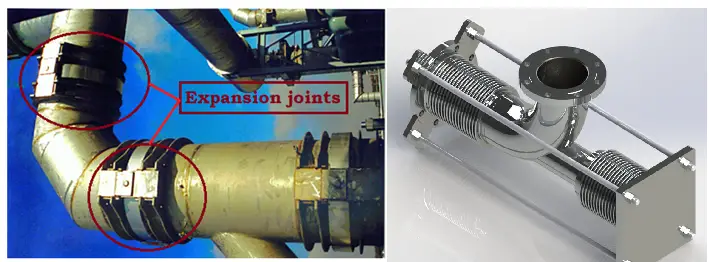
Piping Expansion Joints or Expansion Bellows are highly engineered mechanical devices containing one or more metal/rubber bellows. Expansion Joints are used to absorb dimensional changes caused by thermal expansion or contraction of a pipeline, duct, or vessel while containing the system pressure. The flexible element of the expansion joint that expands or contracts to absorb thermal movement is called Bellows. It consists of one or more convolutions. Expansion joints are successfully used in Refineries, Chemical and Petrochemical Plants, Cryogenic plants, Nuclear power plants, Automotive, Aerospace, and heating & cooling systems.
Why Install Piping Expansion Joints?
Piping Expansion Joints serve various purposes when installed in a piping system. Those are:
- To absorb movement (Thermal expansion as well as compression)
- To relieve system stress and strain.
- To reduce mechanical noise and vibration.
- To have a compact design (space constraint)
- To compensate for misalignment.
- To eliminate electrolysis between dissimilar metals.
- To reduce piping loads on equipment nozzles.
Components of an Expansion Joint
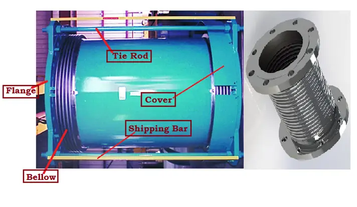
The main components which constitute an expansion joint are as follows:
- Bellow
- Tie Rods
- Flanges
- Shipping Bar
- Protective Covers and Internal Liners
- Special Attachments like Pantographic linkages, etc
Refer to Fig. 1 which shows the main elements of a piping expansion joint.
Bellows:
Bellows are the most important element of a piping expansion joint. This is the basic unit of every expansion joint. They are of two types:
- Formed Bellows
- Formed from a thin-walled tube
- Contains only longitudinal welds
- Single & Multiply
- Fabricated Bellows
- Series of thin gauge discs welded together
- Uses heavier gauge materials than those formed bellows
Regardless of the manufacturing method used, all bellows consist of the same basic components as shown in Fig. 2. Bellows can be single-ply or multi-ply designed.
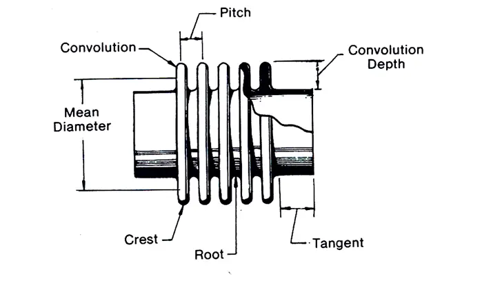
Additional components are added to bellow to create expansion joints of increasing complexity and capability which are suitable for a wide range of applications.
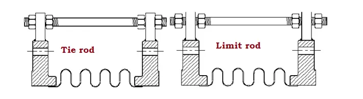
Tie Rod of Expansion Joint:
As the name indicates, Tie rods are basically bars or rods, attached to the expansion joint assembly. Tie rods are designed to absorb pressure loads and other extraneous forces like dead weight. Sometimes, Tie rods (Fig. 3) are used as Limit rods to protect the bellows from movements in excess of design that occasionally occur due to plant malfunction or the failure of an anchor.
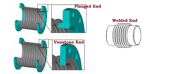
Expansion Joint End Connections:
Three types of end connections (Fig. 4) are available in a piping expansion joint to attach it to a piping system. They are
- Flanged End including Special flanges, slip-on, or angle flanges.
- Vanstone Ends are a type of modified flanged ends that adds flexibility and resolves bolt-hole misalignment.
- Welded ends: Any pipe or duct can be directly welded to such bellows.
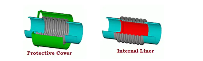
Protective Covers and Liners for an Expansion Joint:
The expansion joint components are put inside a metallic cover to protect them from external sources as shown in Fig. 1.
A liner is provided to minimize the effect of flowing media on the bellow inner surface. Refer to Fig. 5.
Purge connections are provided along with internal liners to reduce the bellow’s skin temperature while using in high-temperature applications such as catalytic cracker bellows. Normal air or steam can be used as a purge medium. Purging helps in flushing out the particulate matter between the bellows and the liner. Harmful solids built up in the convolutions can also be stopped by purging.
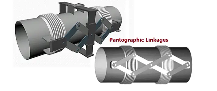
Pantographic Linkages:
Pantographic Linkage is a scissors-like device that is a special form of control rod attached to the expansion joint assembly. They are used to positively distribute the thermal movement equally between two bellows of the universal joint throughout its full range of movement. However, note that they are not designed to restrain pressure thrust.
Types of Expansion Joints
Broadly Piping Expansion Joints can be grouped into two categories:
- Unrestrained Expansion Joint and
- Restrained Expansion Joints
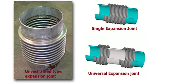
Unrestrained Type Expansion Bellows:
Unrestrained Expansion joints are assemblies not capable of restraining the pressure thrust of the system. So, The pressure thrust must be contained using main anchors or equipment. They are of the following types:
1. Single Expansion Joint Assemblies are the simplest type of expansion joint consisting of a single bellows element welded to end fittings, either flange or pipe ends.
2. Universal Expansion Joint Assemblies consist of two bellows connected by a center spool piece with flange or pipe ends. The main advantage of a universal expansion joint over a single expansion joint is that the universal arrangement provides greater absorption of axial, lateral, and angular movements than a Single Expansion Bellows Assembly.
3. Externally Pressurized Pressure Balanced Assemblies are used when a large amount of axial movement is required to absorb and pressure thrust must be absorbed by the expansion joint. The opposing force balancing theory is quite similar to the In-Line Pressure Balanced Expansion joint Assembly. However, in the current case, the opposing forces are generated from pressure acting on the outside of the bellows.
Restrained Type Piping Expansion Joints:
In Restrained type piping expansion joints, the expansion joint hardware is capable of restraining the pressure thrust of the system by their design. Intermediate anchors are installed to withstand the spring force generated due to the deflection of the expansion joint. The main anchors are not required. They are again of various types as mentioned below:
1. Tied Single Expansion Bellows Assemblies add tied rods to a Single Bellows Assembly to increase design flexibility in a piping system. The tie rods are attached to the pipe or flange with lugs. These tie rods carry the pressure thrust generated in the system, eliminating the need for main anchors.
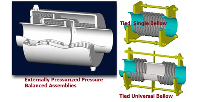
2. Tied Universal Expansion joint Assemblies are mostly similar in construction to a Universal Assembly. The only difference is that tie rods absorb pressure thrust and limit movements to lateral offset and angulation only.
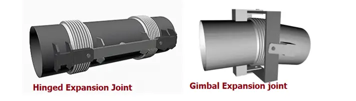
3. Hinged Expansion Bellows Assemblies limit movement to angulation in one plane. Hinged Assemblies (Fig. 9) are normally used in sets of two or three to absorb large amounts of expansion in high-pressure piping systems.
4. Gimbal Expansion Bellows Assemblies are designed to absorb system pressure thrust while allowing angulation in any plane. Gimbal Assemblies (Fig. 9), when used in pairs or with a Single Hinged unit, have the advantage of absorbing movements in multi-planer piping systems.
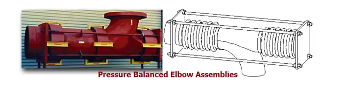
5. Pressure Balanced Elbow Assemblies are used in applications where space limitations are a concern. A system of tie rods or linkages is used in such a fashion that the pressure thrust acting on the line bellows is equalized by the balancing bellows. The only forces transmitted to equipment are low spring forces created by the axial, lateral, or angular movements. An elbow must be present in the piping network to install this style of expansion joint.
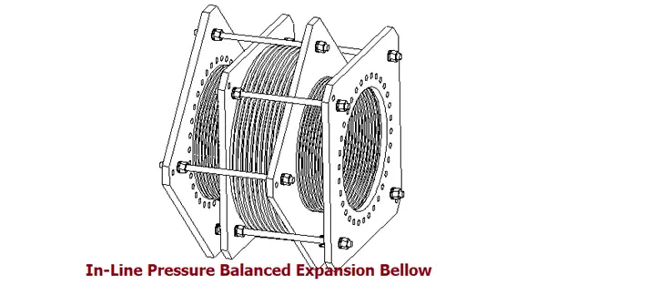
6. In-Line Pressure Balanced Bellows Assemblies are used if a piping elbow is not present in a piping network to use the pressure-balanced elbow assemblies and pressure thrust has to be absorbed by the expansion joint. The inline bellows are tied in the expansion joint through a series of tie rods which equalizes the pressure thrust force. The opposing pressure forces cancel each other leaving only the low spring forces generated from the bellows deflection.
Expansion Joint Materials
The selection of bellows material is another important factor to be considered in the design of a piping expansion joint. Some of the factors which influence the proper expansion bellow the material selection process are:
- Corrosion Properties: Process media, surrounding environment, and internal cleaning agents.
- Mechanical Properties: High-temperature service, cryogenic service, and operating stresses.
- Manufacturing Properties: Forming and cold working capabilities and cost & material availability.
Expansion Joints are available in metallic and non-metallic materials. The most common expansion joint materials, widely used in the piping industry are:
- Stainless steel (Austenitic Steel, SS 304 and SS 316)
- High-grade nickel alloy steels (Inconel, Incoloy, Monel, and Hastelloy)
- Teflon or PTFE
- Glass fiber
- an elastomer such as rubber.
Expansion Joint Design Codes and Standards
Expansion Joints used in industry are designed, manufactured, and tested in accordance with the following Codes and Standards
- EJMA, Expansion Joint Manufacturer Association, Inc.
- ASME B31.3 Appendix X, Metallic Bellows Expansion Joints
- ASME Sec. Ⅷ Div.1, App.26.
- EN 14917 Metal Bellows Expansion Joints for Pressure Applications
Expansion Joint or Bellow Manufacturers
There are many organizations that produce piping expansion joints. few of the most reputed expansion joint industry leaders are:
- U. S. Bellows
- Piping Technology and Products
- Garlock
- SFZ
- Senior Flexonics
- Hyspan
- United Flexible
- Mega-Flexon
- Triad Bellows
- Metraflex, etc.
There are also “sliding Pipe Joints” as expansion joints (only one movement direction). I know them from the pipetrenches and sleeperways in Tank Farms.
Kind Regards, keep up the good work!
General Rubber Corporation are a lead USA manufacturer of Rubber Expansion Joints within the industry. We welcome any opportunity to work with pipe stress engineers in the future.
Visit www.-general-rubber.com for all our company and product details.
Great work on this!
You should include good Indian manufacturers like ‘Flexpert Bellows’ in the list of manufacturers
Hi Owner
I would like to acquire some Flats & I will be needing something like this or similar;
Expansion Joint
Type Single Sphere
Pipe Size 2-1/2″
Connection Drilled
Material Neoprene
Bolt Holes 4
Bolt Hole Size 5/8″
Bolt Circle Dia. 5.5″
Flange Thickness 0.71″
Max. Pressure 225 PSI At 72 Deg F
Temp. Range -50 To 230 Deg F
Vacuum 26 In Hg At 72 Deg F
Outside Dia. 7″
Overall Length 6″
Kindly get back to me with the quote as well as lead time after payment. Also advice if there is a surcharge when making payment via Credit Card
Good information.
We manufacture high end expansion joints , all types!
Hi – can you provide a DN300 and DN400 expansion bellows (ASME 150) for shipment to Ireland? Temperatures up to 850degC.
can we use metal expansion bellows in refinery brine return line ( brine return from the SWRO plant MED plant . line is about 3 km – 54 ” dia. CS line -above ground .
I have a system that needs to remove some axial force due to thermal expansion from pump nozzle
After applying untied expansion joint the axial force due to displacement case removed but a huge axial force in hyrotest and operation load cases have come up.
How can i get rid of these axial forces due to pressure thrust
Yes, this is the thrust force and can be huge. There are some solutions.
First, if it is smaller in diameter, you can use a flexible piping loop. If larger, each leg can be a universal type (two bellows) metal expansion joint instead of a braided hose. We can help with the details if you like.
I have two questions about blow,
1) It is valid if someone uses the same material for bellow and piping.
2) I know we all prefer Caesar II for pipe stress analysis, but it is possible to do pipe system stress analysis ( which includes Bellow in the system) in Ansys and analyze the behavior of bellow.
For 1) maybe.
There are three main materials for expansion joints: stainless (and inconel), rubber, and PTFE. No carbon steel. A bellows made of CS doesn’t work. But the ends of the exp joints, usually flanges, are normally CS on a CS piping system. See on Flexicraft site.
Hello,
I’d like to ask for more explainations on the In-Line Pressure Balanced Bellows Assemblies.
As you explained, “The inline bellows are tied in the expansion joint through a series of tie rods which equalizes the pressure thrust force”, thrust forces are resisted by the tie rods.
Indeed, to me there are 2 types of pressure thrust forces, and which type of thrust load do you mean in the above sentence ?
– Type 1 : pressure thrust force due to the expansion joint’s bellow.
I understood that the type 1 thrust load is resisted by the expansion joint’s tie rods.
– Type 2 : pressure thrust force due to the pipelines’ deviations, for example elbows adjacent to the expansion joint.
Imagine that a fixed-point is installed right next to the expansion joint, on the same horizontal axe.
And right next to this fixed point, there is a elbow which deviates the pipe upwardly.
The thrust load type 2 (due to pressure excerced on the elbow) should be “filtered” by the fixed point, and hence should be taken into account in the conception of the fixed point.
So tie rods are not working in this configuration, regarding the thrust load type 2.
So to me, for the type 2 thrust load, it should depend on the external pipe’s flexibility (as in the example that I cited above).
My question is :
For the In-Line Pressure Balanced expansion joins, the type 2 thrust load is also absorbed by the tie-rods, regardless of the compensator’s external pipe flexibility ?
Thanks in advance for your feedbacks,
Thuy PHAM
1. Where exactly do we need the expansion joints on a steam pipeline? Does it depend on the length of the pipe?
2. How long a pipeline can be laid without using any kind of valve in between? 3″, 4″ ,6″ and 10″ lines of emulsion, crude and steam.