
While “piping” and “pipeline” may sound similar, they refer to different applications and contexts within the broader field of fluid transportation. This distinction affects how wall thickness is considered for each. Here’s a breakdown of the differences between piping wall thickness and pipeline wall thickness:
1. Context and Application
- Piping Wall Thickness:
- Context: Piping typically refers to systems used within facilities such as refineries, chemical plants, power plants, and other industrial settings. These systems transport fluids and gases over short distances within a controlled environment.
- Application: Piping systems are used for processes, utilities, and distribution within a plant. They often involve complex networks with numerous fittings, valves, and pressure vessels.
- Pipeline Wall Thickness:
- Context: Pipelines refer to long-distance transportation systems, often spanning hundreds or thousands of kilometers, and are used to transport oil, gas, water, or other fluids between different locations, such as from a production site to a refinery or from a water treatment plant to a city.
- Application: Pipelines are used for transporting fluids across large geographical areas, typically underground or underwater, with minimal intervention between the start and endpoints.
2. Design Standards and Codes
- Piping Wall Thickness:
- Design Codes: Piping wall thickness is usually governed by standards such as ASME B31.3 (Process Piping), ASME B31.1 (Power Piping), or API 570 (Piping Inspection Code). These standards provide guidelines for calculating wall thickness based on internal pressure, material, temperature, and other factors.
- Thickness Consideration: In piping systems, wall thickness is often designed to handle higher pressure differentials, due to the more complex internal flow paths, higher temperatures, and diverse fluid properties.
- Pipeline Wall Thickness:
- Design Codes: Pipeline wall thickness is generally governed by standards such as ASME B31.4 (Pipeline Transportation Systems for Liquid Hydrocarbons and Other Liquids), ASME B31.8 (Gas Transmission and Distribution Piping Systems), or API 5L (Specification for Line Pipe).
- Thickness Consideration: For pipelines, wall thickness is more influenced by external factors such as ground conditions, potential mechanical impacts (e.g., from excavation equipment), human occupancy, and long-term environmental exposure. The design must ensure the pipeline can withstand the pressure over long distances with minimal maintenance.
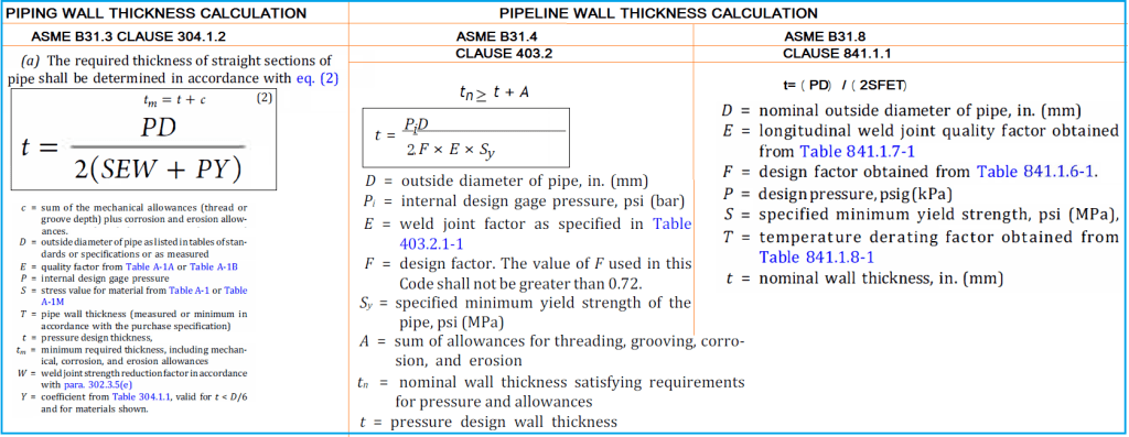
3. Piping and Pipeline Wall Thickness Calculation Equation
The pipe wall thickness calculation for piping and pipeline systems is provided in Fig. 1 below:
To learn more about piping wall thickness calculation visit Pipe Thickness Calculation as per ASME B31.3 | Pipe Thickness Calculator and Pipe Thickness Calculation of Straight Pipe under External Pressure/ Vacuum Pressure Condition. However to know the steps for pipeline wall thickness calculation visit Steel Pipeline Wall Thickness Calculation With Example and Steps for Pipeline Wall Thickness Calculation with Case Study.
4. Pressure Considerations
- Piping Wall Thickness:
- Pressure Levels: Piping systems within facilities typically handle a wide range of pressures, including very high pressures, depending on the process requirements. Therefore, the wall thickness is often calculated with higher precision to manage these variable pressures.
- Pressure Drop: Piping systems experience more frequent pressure drops due to the complexity of the network, with numerous bends, valves, and fittings. This variability in pressure requires careful consideration of wall thickness.
- Pipeline Wall Thickness:
- Pressure Levels: Pipelines generally operate under a more consistent pressure, which is determined by the distance and the elevation changes along the pipeline route. The wall thickness is designed to manage the steady state pressure over long distances, ensuring durability and integrity.
- Pressure Drop: Pressure drop in pipelines is usually managed over long distances using booster stations. The wall thickness is selected to handle the maximum pressure expected in the system, considering factors like terrain elevation and flow rate.
5. Piping and Pipeline Thickness Values
Piping thicknesses after calculating the minimum required thickness are always selected from ASME B36.10 or ASME B36.19. So, all pipe thicknesses in the piping industry are mostly standard thicknesses (Also known as pipe schedules). However, as pipelines run for several kilometers, tonnage cost matters a lot. In this respect to reduce cost, pipeline thickness is selected as a non-standardized value. For example, let’s assume in your pipe thickness calculation, you got the calculated thickness as 4.8 mm for an 8″ pipe size. In general, for a piping system the selected thickness will be 8″, Sch 20 means 6.35 mm whereas for pipeline system the selected pipe wall thickness will be 4.8 mm.
6. Material and Corrosion Allowance
- Piping Wall Thickness:
- Material: Piping systems often use a wider range of materials, including carbon steel, stainless steel, alloy steel, and non-metallic materials like PVC or HDPE. The choice of material influences the wall thickness, especially when dealing with corrosive or high-temperature environments.
- Corrosion Allowance: In industrial settings, where pipes may be exposed to harsh chemicals or corrosive fluids, a significant corrosion allowance may be added to the wall thickness. This ensures that the pipe remains safe over its expected service life, even as it experiences material degradation.
- Pipeline Wall Thickness:
- Material: Pipelines are predominantly constructed from carbon steel, with specialized coatings and cathodic protection systems to prevent corrosion over long distances. Material selection is crucial for managing both internal corrosion (from the fluid being transported) and external corrosion (from the environment).
- Corrosion Allowance: For pipelines, the corrosion allowance is often integrated into the initial design, with additional protective measures like coatings and cathodic protection to ensure longevity. The wall thickness must be sufficient to last for decades with minimal maintenance.
7. Environmental and Mechanical Loads
- Piping Wall Thickness:
- Environmental Loads: Piping within facilities is generally protected from environmental conditions like extreme temperatures, UV radiation, and mechanical impacts. However, thermal expansion, vibration, and support loads are critical considerations.
- Mechanical Loads: Piping systems must account for mechanical loads from supports, thermal expansion, and vibration. These loads can influence the required wall thickness, especially in high-stress areas like bends or connections to equipment.
- Pipeline Wall Thickness:
- Environmental Loads: Pipelines are exposed to a variety of environmental conditions, including temperature extremes, soil movement, and potential mechanical impacts from external sources (e.g., digging, landslides). The wall thickness is often designed to withstand these external threats.
- Mechanical Loads: In addition to internal pressure, pipelines must withstand mechanical loads from ground movement, external impacts, and installation processes. This requires a robust wall thickness to prevent failures in harsh environments.
8. Inspection and Maintenance
- Piping Wall Thickness:
- Inspection: Piping systems within facilities are regularly inspected, with wall thickness measurements taken periodically to assess corrosion and wear. This frequent inspection allows for adjustments or replacements before significant failures occur.
- Maintenance: Maintenance in piping systems is more frequent and accessible, given the proximity and accessibility within industrial plants. Wall thickness considerations must account for the ease of repair or replacement.
- Pipeline Wall Thickness:
- Inspection: Pipelines, due to their length and remote locations, are inspected using methods like pigging (pipeline inspection gauges) and remote sensing technologies. Wall thickness is designed to minimize the need for frequent inspections.
- Maintenance: Pipeline maintenance is more challenging and costly due to the remote and inaccessible nature of many pipeline routes. As such, the wall thickness must be designed for long-term reliability with minimal intervention.
Piping and Pipeline Diameter Chart
The following table provides a piping and pipeline diameter chart. Note that, the outside diameter (OD) of steel pipe in piping and pipeline applications is constant for the same pipe size. However, the Internal diameter will vary depending on the thickness. To give an example, the OD of a 10″ steel pipe will be 273.05 mm whether it is used in a piping or pipeline application.
| Sr No | Pipe Nominal Size (NPS) | Pipe Outer Diameter (mm) | Pipe Outer Diameter (inches) |
|---|---|---|---|
| 1 | 1/2 | 21.34 | 0.84 |
| 2 | 3/4 | 26.67 | 1.05 |
| 3 | 1 | 33.40 | 1.32 |
| 4 | 1 1/4 | 42.16 | 1.66 |
| 5 | 1 1/2 | 48.26 | 1.90 |
| 6 | 2 | 60.33 | 2.37 |
| 7 | 2 1/2 | 73.03 | 2.87 |
| 8 | 3 | 88.90 | 3.50 |
| 9 | 3 1/2 | 101.60 | 4.00 |
| 10 | 4 | 114.30 | 4.50 |
| 11 | 5 | 141.30 | 5.56 |
| 12 | 6 | 168.28 | 6.63 |
| 13 | 8 | 219.08 | 8.63 |
| 14 | 10 | 273.05 | 10.75 |
| 15 | 12 | 323.85 | 12.75 |
| 16 | 14 | 355.60 | 14.00 |
| 17 | 16 | 406.40 | 16.00 |
| 18 | 18 | 457.20 | 18.00 |
| 19 | 20 | 508.00 | 20.00 |
| 20 | 22 | 558.80 | 22.00 |
| 21 | 24 | 609.60 | 24.00 |
| 22 | 26 | 660.40 | 26.00 |
| 23 | 28 | 711.20 | 28.00 |
| 24 | 30 | 762.00 | 30.00 |
| 25 | 32 | 812.80 | 32.00 |
| 26 | 34 | 863.60 | 34.00 |
| 27 | 36 | 914.40 | 36.00 |
| 28 | 38 | 965.20 | 38.00 |
| 29 | 40 | 1016.00 | 40.00 |
| 30 | 42 | 1066.80 | 42.00 |
| 31 | 44 | 1117.60 | 44.00 |
| 32 | 46 | 1168.40 | 46.00 |
| 33 | 48 | 1219.20 | 48.00 |
| 34 | 50 | 1270.00 | 50.00 |
| 35 | 52 | 1320.80 | 52.00 |
| 36 | 54 | 1371.60 | 54.00 |
| 37 | 56 | 1422.40 | 56.00 |
| 38 | 58 | 1473.20 | 58.00 |
| 39 | 60 | 1524.00 | 60.00 |
This table provides the nominal pipe sizes (NPS), and the corresponding outer diameters in both millimeters and inches for steel pipes ranging from 1/2 inch to 60 inches.
In summary, the differences between piping wall thickness and pipeline wall thickness stem from their distinct applications, operating conditions, design codes, and design requirements. While both are critical for ensuring the safety and integrity of fluid transport systems, the considerations for each are tailored to the specific challenges and environments they face. Understanding these differences is essential for engineers and designers to select the appropriate wall thickness for their specific needs.
In AutoPIPE, I entered a corrosion allowance of 2 mm for a pipe with a thickness of 15.9 mm. The calculated required thickness is 12.11 mm, so including the corrosion allowance, the required thickness becomes 14.11 mm. However, the model still shows that MaxP is failing. Could you please help me understand why this might be happening?