Piping systems under vacuum conditions, Jacketed Piping, Offshore pipelines, piping inside equipment, etc. are subjected to both internal as well as external pressure. Contrary to the internal pressure, external pressure compresses the material, and Failure of piping under squeezing action can occur at lower pressure. This is due to elastic buckling. The pipe geometry is weaker in compression than in tension and failure can occur well below the yield point under the influence of external pressure. So, the piping system must be designed to withstand external pressure.
External pressure pipe wall thickness calculation must be performed for all lines having the possibility of external pressure or vacuum pressure. By preliminary understanding, it may seem that as the internal design pressure is usually more than the external design pressure, so designing for internal pressure will take care of the external pressure design thickness as well. But this is not the case. As the piping system behaves differently under vacuum or external pressure conditions. Due to the buckling consideration all design philosophy changes for external pressure design thickness calculation.
For straight pipe under external pressure, two checks are performed:
- First is the membrane stress check in accordance with pipe thickness calculation based on internal pressure Eq. (3a) [or (3b)] of ASME B31.3 (Clause 304.1.2).
- The second check is a buckling check (As specified in Clause 304.1.3 of ASME B31.3) in accordance with the external pressure design rules outlined in ASME BPVC, Section VIII, Division 1, UG-28 through UG-30. The design length, L, the running centerline length between any two sections stiffened in accordance with UG-29 means the length between flanges, heads, stiffeners, etc.
In this article, we will explore the external pressure pipe thickness calculation steps with an example problem.
External Pressure Pipe Wall Thickness Methodology
In external pressure design pipe thickness calculation, initially, a pipe thickness is calculated based on internal pressure conditions. Please click here to explore the steps required for pipe wall thickness calculation for internal pressure using ASME B 31.3.
Once the pipe thickness is selected based on internal pressure, that pipe thickness is checked with respect to buckling following ASME BPVC UG-28 rules to find if that thickness is sufficient for external pressure conditions. So, this is basically verification of the selected pipe thickness as per ASME B 31.3, clause 304.1.3, and ASME BPV Code, Section VIII, Division 1, UG 28.
ASME BPV code provides two separate procedures for calculating the minimum required thickness, for Do/t >= 10 and Do/t <10. Here Do=Outside Diameter of the Pipe and t=Minimum required thickness.
Buckling pressure calculations in ASME BPVC, Section VIII, Division 1 require the calculation of two parameters; A and B.
- Parameter A is a function of geometry and
- Parameter B depends on A and the material property curve. The charts that provide parameter B account for plasticity between the proportional limit of the stress-strain curve and the 0.2% offset yield stress.
Example Problem for External Pressure Design Pipe Thickness Calculation
We will consider a 32″ Carbon Steel Pipe with 31.75 mm thickness with the following parameters for external pressure design thickness calculation.
- P : External Pressure = 15 psi Section
- Do: Outside Diameter of pipe = 813 mm for 32″ pipe (as per ASME B36.10M)
- L: Assumed unstiffened length of pipe = 12000 mm (472.4 inches), (based on the piping layout for calculation purposes).
- T: Selected Pipe wall thickness based on internal pressure = 31.75 mm;
- t: Selected Thickness less mill tolerance of 0.3 mm and corrosion allowance of 3 mm = 28.45 mm (1.12 inch)
- T: Design temperature = 149 Deg. C
- Y: SMYS of the material = 35000 psi
- E: modulus of elasticity of the material at design temperature = 294000000 psi
External Pressure Design Pipe Thickness Verification Steps
Step-1: Calculation of Do/t
Calculate Do/t; Here Do=32″ and t=1.12 “. So Do/t=32/1.12=28.57 which is greater than 10.
So we will follow the first method of ASME Sec VIII Div 1.
Step-2: Finding L/Do
Find L/Do;
Here, L=472.4″ and Do=32″; Hence L/Do=14.76- approximately 15
Step-3: Finding Factor A
Finding Factor A from Fig. G of ASME Sec II, Subpart 3, Part D,
For finding factor A, Enter ASME BPVC Section II, Part D, Subpart 3, Figure G at the value of L/Do and Do/t determined in Steps 1 and 2. The figure is reproduced below in Fig. 1 for sample reference purposes.
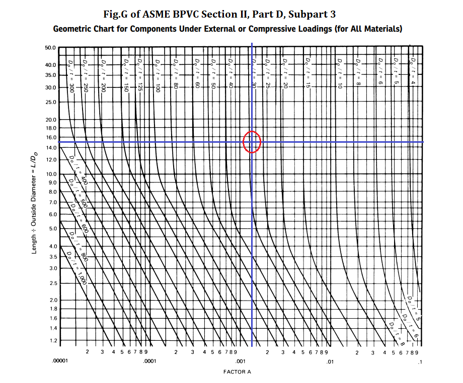
From Fig.1; The factor A=0.00135.
Step-4: Finding Factor B
Determining the value of Factor B
Using the values of A calculated in step 3 (A=0.00135 for our case), enter the applicable material chart in subpart 3 of Section II, Part D.
As our material is CS with SMYS=35000 psi, we have to refer to Fig. CS-2. (Reproduced in Fig. 2 for reference)
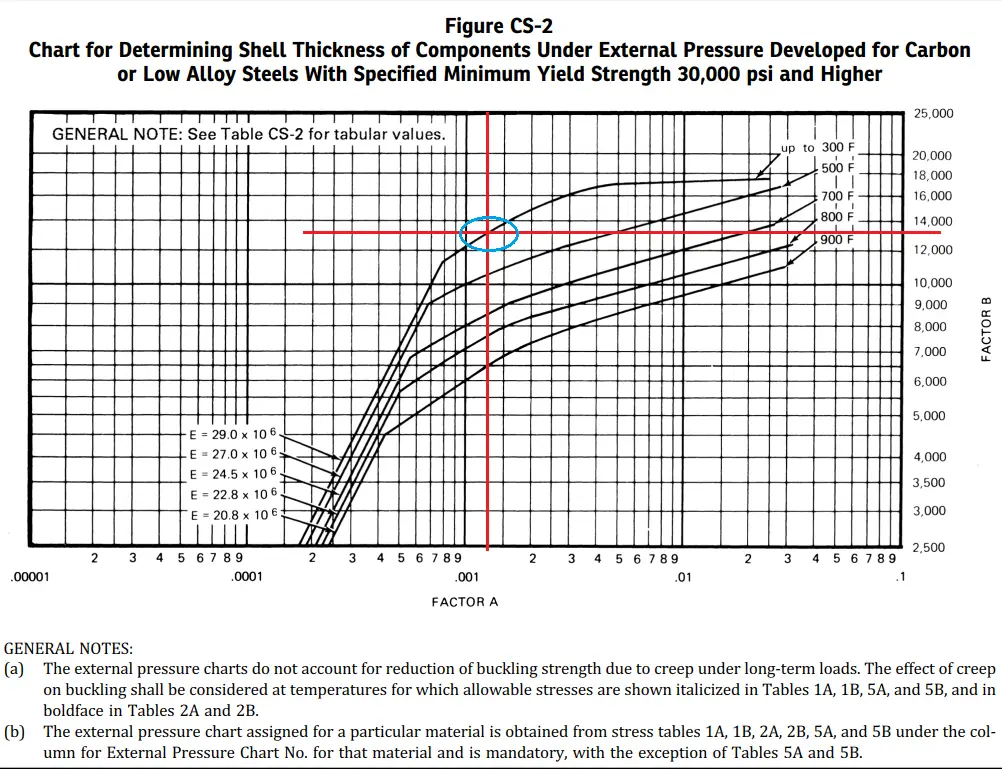
From the curve value of Factor B=13200.
In cases where the value of A falls to the right of the end of the material/temperature line, assume an intersection with the horizontal projection of the upper end of the material/temperature line. If tabular values are used, the last (maximum) tabulated value shall be used.
Step-5: Calculating Maximum Allowable External Working Pressure, Pa
Calculation of Maximum Allowable External Working Pressure Pa
Now, Using this value of B (as calculated in Step-4), calculate the value of the maximum allowable external working pressure Pa using the following equation (Fig. 3):
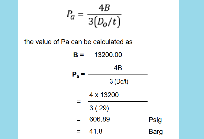
Since Pa (606.89 psi) > P (15 psi), the selected pipe wall thickness can withstand full vacuum. So our pipe is safe for a full vacuum condition.
Few more useful Resources for you.
Pipeline wall thickness calculation with example
Meaning of Pipe Schedule / Schedule Numbers?
Piping Layout and Design Basics

Really helpful. Expecting more such blogs like this because i am just a beginner so want to learn more.
Since in this calculation, ASME sec VIII pressure vessel code is used, can you explain how to calculate un-stiffened length assuming there is no stiffening rings provided on the pipes. Please clarify L can be taken as maximum distance between pipe supports or maximum distance between elbows. If distance between supports is taken as L, please confirm supports shall be Hold down guide or simple rest supports.
Plate welded to pipe for a line stop or anchor would count as stiffening as would flanges Elbows and Equal Tees.
Lines of Do/t on Figure G become constant at large values of L/Do. So A becomes constant at large values of L/Do.
Buckling occurs due bending, external pressure or combination of external pressure and bending. Distance between supports would be important for bending but as above a line stop or anchor would count as a stiffener for external pressure.
As per external pressure calculation “ASME BPV code provides two separate procedures for calculating the minimum required thickness, for Do/t >= 10 and Do/t <10."
What is the procedure for Do/t <10?
Clear to me plz engineer
Factor A:0.00135
B:13000 SO A:0.00125
B14000 SO A:0.00175
How you obtain these with rulers???
Using interapolation between 13000 & 14000 subsequently 13200 ?!!!! So in other website got 13600 why difference value you 13200 for factor B (Factor A:0.00135) and others 13600 ( Factor A:0.0014 ) Could you explain your calculation to get 3200?
Value of E at 150 deg. C cannot be 294… it should be 194.