
The purpose of pressure safety valves is to shield machinery from extreme overpressure. In addition to offering the necessary protection, appropriately sized relief valves can help prevent problems caused by high flow rates, such as undersized discharge pipes and effluent handling systems, potential valve damage, decreased performance, and increased expenses. Increased vessel pressure can arise from a variety of conditions, and each scenario may call for a different valve size. Finding the most modest sizing usually requires doing several case studies. Typical examples include the following:
- a run-away reaction,
- a loss of cooling,
- thermal expansion of a liquid, or
- an external fire.
Under each of these conditions, the pressure will rise until it reaches a pre-set relief pressure, after which the relief pressure valve is actuated and the pressure will drop following the turnaround time.
Design and Sizing Terms
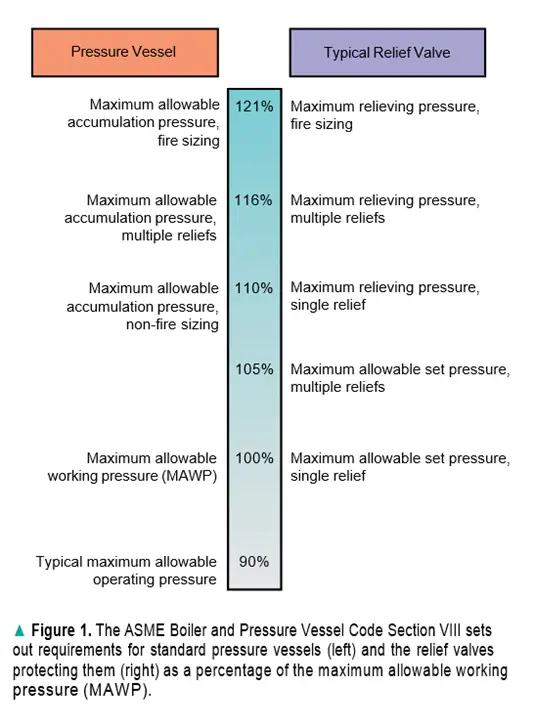
MAWP: The maximum allowable working pressure (MAWP) is the main parameter used to describe a pressure vessel. The maximum acceptable pressure at a vessel’s top at a certain temperature is known as the MAWP.
MAWT: The maximum acceptable working temperature (MAWT) is the name given to this specified temperature. The MAWT is significant because, due to the metal’s decreased strength, the MAWP drops as temperature rises. In addition, embrittlement could be a problem at extremely low operating temperatures (about –20°F).
Set Pressure: A relief device’s set pressure is the value of pressure at which it functions. Small quantities of leakage begin to occur with spring-operated relief valves at 92–92.5 percent of the set pressure.
Over Pressure: The pressure rise over the set pressure of a relief device is known as overpressure, and it is often stated as a proportion of the set pressure. Pop-acting relief valves do not open fully (to 100% lift) right away. It takes enough overpressure to get the maximum lift. The entire rated capacity of ASME-certified relief valves must be reached at 10% or less over-pressure. The National Board of Boiler and Pressure Vessel Inspectors has code-certified relief valves. Conducting flow testing under ASME code-specified conditions is part of the code certification process.
The degree of pressure increment above the MAWP typically represented as a percentage of the MAWP, is known as pressure vessel accumulation. Both the buildup and the overpressure are equivalent when the pressure relief device is at the MAWP.
Back Pressure: The pressure below the relief device is known as back pressure. It consists of the built-up backpressure from the fluid discharge through the relief device down the subsequent piping and/or treatment system, as well as the continuous superimposed backpressure.
Relief Device Sizing:
The most popular guide for sizing relief devices in the chemical manufacturing sectors is API 520 Part 1 (3), the American Petroleum Institute’s Guideline Procedure for Sizing, Selection, and Installation of Pressure-Relieving Systems in Refineries.
Determining the necessary relief area for the relief device is the goal of the relief sizing calculation. The specific design challenges and special factors that are specific to each installation of a relief device will affect the relief sizing estimates. To find these problems, the steps listed in the flowchart shown in Figure 2 need to be followed. This article outlines a general sizing process that only addresses sizing calculations for standard spring-operated devices in liquid and gas (vapor) service.
Sizing for Liquid service:
The most popular guide for sizing relief devices in the chemical process industries is API 520 Part 1 (3), the American Petroleum Institute’s Suggested Procedure for Sizing, Selection, and Installation of Pressure-Relieving Systems in Refineries.
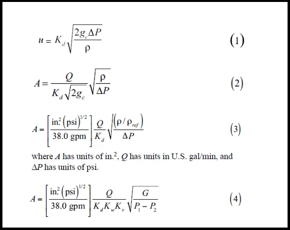
Finding the necessary relief area for the relief device is the aim of the relief sizing calculation. The specific design challenges and special factors specific to each installation of a relief device will affect the relief sizing estimates. This article outlines a general sizing process that only addresses sizing calculations for standard spring-operated devices in liquid and gas (vapor) service. For liquid service, the sizing calculation is based on the fundamental equation for liquid discharge through an orifice.
Where
- u is the average discharge velocity of the fluid through the relief orifice (distance/time);
- Kd is the effective discharge coefficient (unitless);
- gc is the gravitational constant (distance-mass/force-time2);
- Q is the volumetric flow of liquid;
- A is the Orifice area;
- ∆P is the pressure drop across the orifice (force/area); and
- Þ is the density of the fluid (mass/volume).
The unitless discharge coefficient, Kd, is normally provided by the valve manufacturer. It can also be obtained from the ASME National Board of Boiler and Pressure Vessel Inspectors for code-certified devices. For preliminary sizing, a value of Kd = 0.65 is assumed.
Equations 1–3 model liquid discharge through an orifice with fully turbulent flow. Equation 3 must be adjusted for the viscosity of the fluid; a fluid with a higher viscosity requires a larger orifice. Equation 3 must also be adjusted for back- pressure if a balanced-bellows relief valve is selected. Incorporating these adjustments into Eq. 3 results in the equation 4 in Fig. 2:
In Equation 4,
- Kw is the adjustment factor for backpressure (unitless); Kw can be determined from Figure 3.
- Kv is Kv is the unitless viscosity correction factor and can be determined from Figure 3.
- G is the specific gravity of the liquid referenced to water at 70°F, which is equal to Þ / Þref;
- P1 is the upstream relieving pressure (gage pressure), which is the set pressure plus allowable overpressure.
- P2 is the total back pressure (gauge pressure).
Viscosity adjustment is not required for Reynolds numbers higher than 16,000 (i.e., Kv = 1.0). However, the relief area needs to be specified to compute the Reynolds number. It can be necessary to solve Eq. 4 by making mistakes. Determine the relief area first, assuming Kv=1.0, and then the Reynolds number.
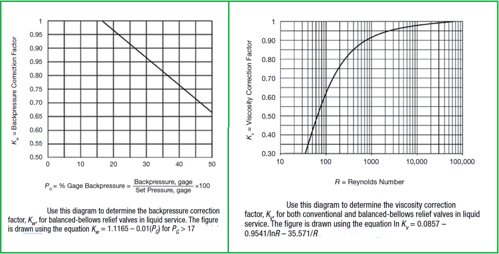
The Reynolds number, on the other hand, will typically be far higher than 16,000. On the other hand, if the value of the Reynolds number is less than 16,000, compute a new relief using Figure 3 to ascertain a new viscosity correction factor.
Repeat this procedure until the solution converges on a Reynolds number.
Usually, Kw and Kv values are obtained from the manufacturer, but for preliminary sizing, we can determine by Figure 3.
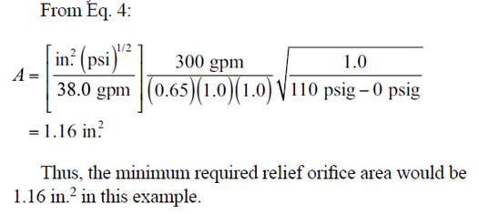
Liquid Sizing Example
According to a study, a process vessel’s standard spring-operated relief valve has to provide 300 gpm of water flow to function. Let’s say there is a predetermined pressure of 100 psig and an overpressure of 10%. Backpressure adjustment is not required for a standard relief valve (Kw = 1.0). 300 gpm is the volumetric discharge rate (Q) through the relief valve. There is no information regarding the discharge coefficient, Kd; as a rough approximation, use Kd = 0.65. It is unknown what Reynolds number passes through the relief valve. At 300 gpm volumetric discharge rate, though, the Reynolds number is most likely higher than 16, 000. Thus, assume Kv = 1.0. The liquid is water at 70°F, so G = (Þ / Þref) = 1.0.
Sizing for Gas Service
Choked flow via the relief orifice is envisaged for standard spring-operated relief devices in gas or vapor service. The following equation represents choked flow via an orifice:
Where
- P1 is the upstream relieving pressure for vapor service (absolute pressure);
- Kd is the discharge coefficient (unitless);
- W is the mass flow rate (mass/time).
- Ƴ is the gas/vapor capacity ratio (Unitless).
- The gravitational constant, or gc (mass/force/time2),
- M is the gas’s molecular weight (mass/mol).
- T is the absolute temperature (degrees),
- and Rg is the ideal gas constant (pressure-volume/mol-deg.).
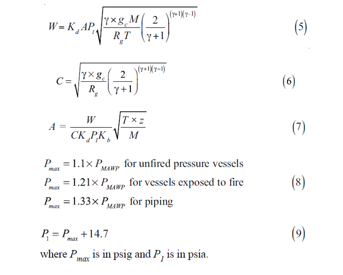
The word C, which is a function of simply the heat capacity ratio, is defined as follows to make the calculation simpler:
To compensate for nonideal gas behavior, equation 5 is adjusted by adding the compressibility factor, z, and the back-pressure correction, Kb. Equation 5 can be calculated for the relief area with the following modifications:
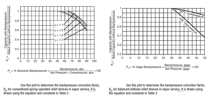
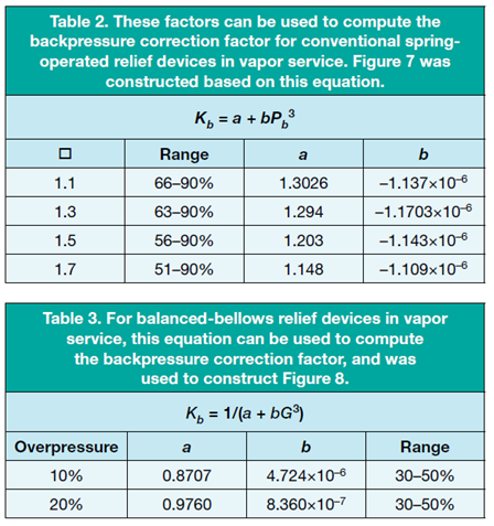
Typically, Kd and Kb are supplied by the valve maker. A discharge coefficient, Kd, of 0.975 is utilized for initial sizing. Figure 5 can be used to calculate the backpressure will correction factor, Kb, regardless of whether the relief device is a balanced-bellows valve or a traditional spring-operated device. The equation in Table 2 provided the data for Figure 5, while the equation in Table 3 provided the data for Figure 6.
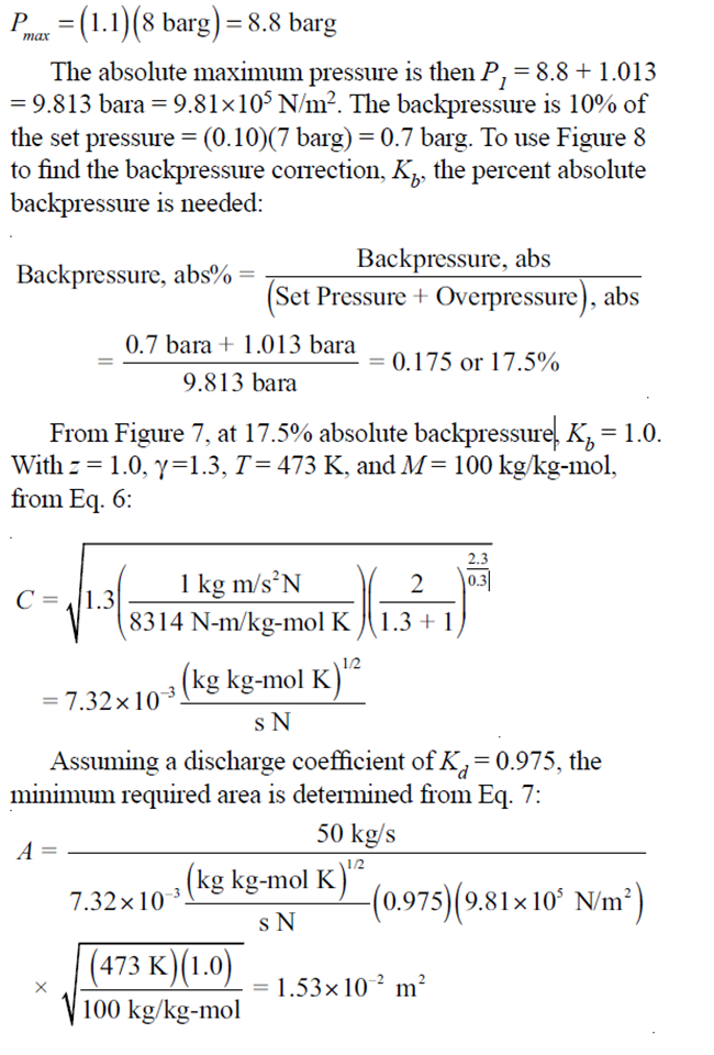
In Figure 6, Kb is determined by the back pressure to set pressure ratio. As seen in Figure 5, Kb depends on the ratio of backpressure to Pmax, the highest permissible relieving pressure, which is established by the permissible accumulation: where PMAWP and Pmax are expressed in units of gauge pressure. The backpressure and Pmax need to be transformed to pressure in absolute units using an equation like this to use Figure 5.
Gas Sizing Example:
The size of a spring-operated relief device needs to match the ideal hydrocarbon vapor pressure vessel. The mass discharge rate, W, in the controlling scenario, is 50.0 kg/s. Assume that the process temperature is 473 K, the vessel PMAWP is 8 barg, there is no superimposed backpressure, and the built-up backpressure is equal to 10% of the set pressure. After reviewing typical operating pressures, it is decided to employ a fixed pressure of 7 barg, or Ps. The vapor is perfect, with z = 1.0, and has a molecular weight in 100. Its heat capacity ratio is 1.3. Since this is an unfired pressure vessel, the maximum permissible relieving pressure in gauge units, derived from Equation 8, is:
References:
- Kelly, B. D., “What Pressure Relief Really Means,” Chem. Eng. Progress, 106 (9), pp. 25–30 (Sept. 2010).
- Crowl, D. A., and J. F. Louvar, “Relief Sizing,” Chapter 10
- in “Chemical Process Safety: Fundamentals with Applications,” 3rd ed., Prentice Hall, Englewood Cliffs, NJ, pp. 459–503 (May 2012).
- American Petroleum Institute, “Recommended Practice for the Sizing, Selection, and Installation of Pressure-Relieving Systems in Refineries,” API RP 520, Part 1, 8th ed., API, Washington, DC (2008).
- Fisher, H. G., et al., “Emergency Relief System Design Using DIERS Technology,” American Institute of Chemical Engineers, New York, NY (1992).
- Anderson Greenwood and Crosby, Technical Service Manual, www.andersongreenwood.com/literature.asp (Aug. 2013).
- American Society of Mechanical Engineers, “Boiler and Pressure Vessel Code,” Section VIII, “Rules for Construction of Pressure Vessels,” ASME, New York, NY (2013).
ADDITIONAL RESOURCES
- American Institute of Chemical Engineers, “Guidelines for Pres- sure Relief and Effluent Handling Systems,” Center for Chemi- cal Process Safety (CCPS), New York, NY (1998).
- Hellemans, M., “The Safety Relief Valve Handbook,” Elsevier, Oxford, U.K. (2009).
- Malek, M., “Pressure Relief Devices,” Mc-Graw-Hill, New York, NY (2005).