
Produced Water Source
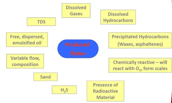
Hydro Carbon reservoirs always have water along with crude/gas. The water(brine) brought to the surface from the hydrocarbon-bearing reservoirs during the extraction of oil and gas can include formation water, injection water, and any chemicals added downhole or during oil/water separation processes is termed “Produced Water”. The produced water is very high in salt content and also contains oil in dispersed form and therefore needs to be treated before it is disposed of. This article will mostly concentrate on the Conventional Methods for Oil Removal from Produced Water.
Contaminants in Produced Water
Produced Water Disposal
The major disposal/re-use of Produced Water are
- Re-Injection for Pressure Maintenance
- Injection in Disposal wells
- Overboard Discharge
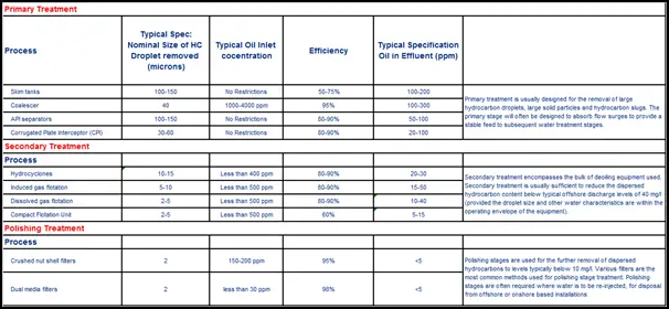
Every disposal mechanism has quality criteria, and the same shall be met before disposal. The typical disposal criteria are as given below:
| Criteria | Water Injection | Injection in Disposal Wells | Overboard Discharge |
| OiW (ppm) | ~10 ppm | 10-40 ppm | 40 ppm-100 ppm# |
Produced Water Cycle
A typically produced water cycle is shown in Fig. 2
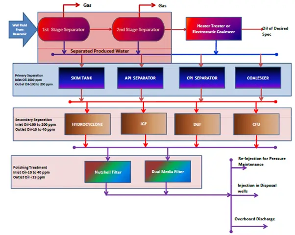
Classification of Produced Water Treatment Process
Refer to Fig. 3 which explains the classification of Produced Water.
Produced water Treatment Processes
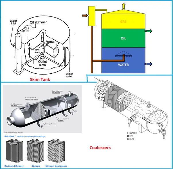
Produced water Treatment using SKIM TANK (Fig. 4):
- Principle: Gravity Separation
- Description and Operation:
- Designed to provide long residence times.
- Their design can include a simple tank with water inlet/outlet baffles and an oil skimmer.
- In some designs, the well fluid first flows into a degassing chamber. Liquids flow down into the tank, and exit under a cone or spreader.
- In some designs, the oil and water compartments are separated within the tank and the skimming is ensured by Interface control.
Advantages and Disadvantages of Produced Water Treatment using Skim tank:
- Provide large surge capacity ensuring stable flow to downstream
- Large residence time also ensures solids separation
- Require Large Footprint area
- Produced water channeling (short-circuiting) recirculation or stagnant areas of fluid can occur due to poor internal design or build-up of solids.
Produced water Treatment in COALESCER (Fig. 4):
- Principle: Coalescing and Gravity Separation
- Description and Operation:
- Coalescer includes installation of Coalescer Plates or Packs in the conventional separator
- The pack provides more surface for suspended oil droplets to coalesce into larger globules.
- In the separation process, the oil droplet size is very significant, therefore it is also installed upstream of separation devices to increase the Oil particle Sizes and thereby the efficiency of the downstream equipment.
Advantages and Disadvantages of Produced Water treatment in Coalescer:
- No moving parts and simple control
- Little maintenance or attention required
- Can handle high levels of oil in the produced water
- Capable of handling relatively large oil content fluctuations
- Plates can block with solids or fouling hydrocarbons.
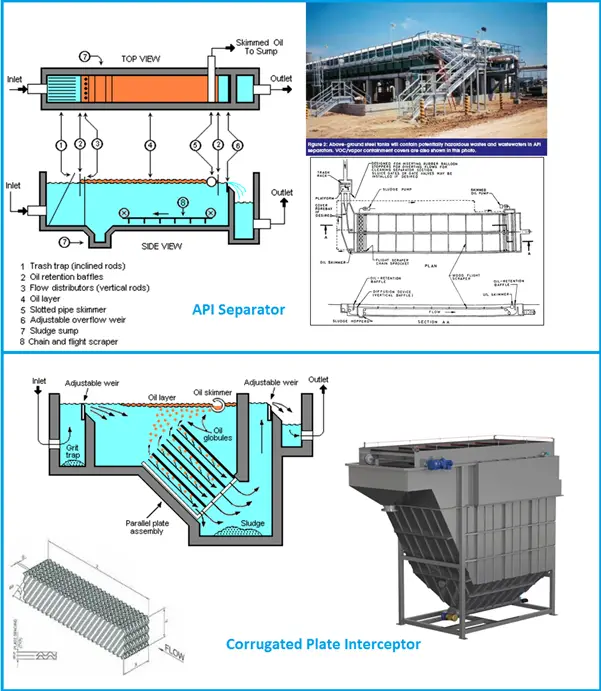
Produced Water Treatment in API SEPARATOR (Fig. 5):
- Principle: Gravity Separation
- Description and Operation:
- Fluid Enters at one end and separates along the length as per density.
- Most of the suspended solids will settle to the bottom of the separator as a sediment layer, the oil will rise to the top of the separator, and the wastewater will be the middle layer between the oil on top and the solids on the bottom.
- Typically, the oil layer is skimmed off and re-processed or disposed of.
- The bottom sediment layer is removed by a chain and flight scraper (or similar device) and a sludge pump.
- The water separated is sent for further processing.
Advantages and Disadvantages of Produced water Treatment in API Separator:
- Simple in design
- Large residence time also ensures solids separation
- Is a very old design and has been replaced by a CPI separator
- Solids removal from the bottom is difficult and separated solids affect the separator’s efficiency
- Large footprint area
- Atmospheric Design-Cannot be used for PWRI
- Need a degasser to be installed upstream
Using CORRUGATED PLATE INTERCEPTOR (CPI-Fig. 5) for Produced Water Treatment:
- Principle: Gravity Separation
- Description and Operation:
- Fluid Enters at one end and separates along the length as per density just like an API Separator
- CPI includes corrugated plates arranged in a plate pack which is installed at an angle of 45°
- The plate provides more surface for suspended oil droplets to coalesce into larger globules.
- Separated solids would slide down and separated oil drops move upwards due to their lesser density than water.
Advantages and Disadvantages of Corrugated Plate Interceptor in Produce Water Treatment:
- Corrugated plates enhance the degree of oil-water separation and therefore it requires significantly less space than a conventional API separator
- Atmospheric Design-Cannot be used for PWRI
- Need a degasser to be installed upstream
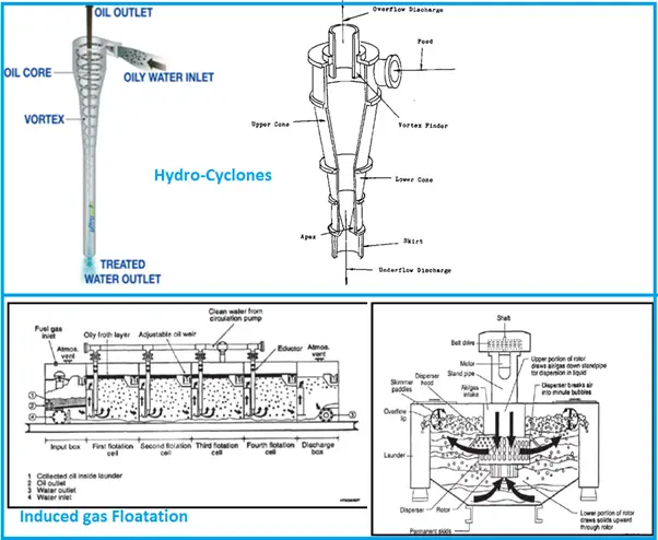
Produced Water Treatment in HYDRO-CYCLONES (Fig. 6):
- Principle: Centrifugal Force
- Description and Operation:
- Fluids enter the hydro-cyclone through the tangential inlet at the top which causes the fluids to spin and attain High Centrifugal forces
- The centrifugal forces in a hydro-cyclone are of the order of several hundred times normal gravity force. This promotes rapid separation.
- The clean water exits the Hydro-cyclone through the open end of the Tube at bottom
- A vortex finder in the outlet port reverses the direction of the hydrocarbon core and it is discharged under differential pressure control, from the reject port at the center of the Inlet End
- In order to maintain hydro-cyclone separation efficiency, the Pressure Differential Ratio (PDR) must be maintained within certain limits. The PDR is defined as follows: PDR=DPir/Dpio Where, DPir = Pressure at the inlet – Pressure at reject outlet; DPio = Pressure at the inlet – Pressure at water outlet; Oil removal efficiency will decline <1.5=1.7-2.0=<Volume of liquid routed to the reject increases
Advantages and Disadvantages of Produced water Treatment in Hydro-Cyclones:
- Compact in design
- High Efficiency @ particle size less than 10microns
- Modular Design gives flexibility for capacity enhancement
- The energy Requirement to pressurize Inlet is high
- High cost due to the Metallurgy-Erosion Issues
Using Induced Gas Floatation(IGF-Fig. 6) for Produced water Treatment
- Principle: Froth Floatation
- Description and Operation:
- IGF units operate by generating small gas bubbles and releasing these in the lower section of a vessel through which the water is flowing.
- These bubbles attach themselves to the dispersed hydrocarbon droplets, reducing their density and floating them to the liquid surface.
- The separated hydrocarbon is then removed and the treated water exits the vessel under level control.
- There are two methods of Inducing bubbles viz. Mechanical and Hydraulic
- The Mechanical method generated gas bubbles by means of motor-driven diffusers/impellers.
- The unwanted side effect of the shear forces required to generate the micron-sized gas bubbles was a reduction in the size of the oil droplets which adverse effect on the overall efficiency of these units.
- The Hydraulic method uses a stream of clean water from the outlet and mixes it with the gas from the vessel top in an eductor. The mixed stream is then injected into the floatation cells through nozzles.
- Hydraulically inducing the bubbles results in lower shear forces in the flotation cell
Advantages and Disadvantages of Induced Gas Floatation for Produced Water Treatment:
- Low Capex
- High Inlet concentration can be acceptable
- Relatively insensitive to changes in oil droplet size
- Require steady flow for the effective operation
- Normally requires a de-oiling chemical to be dosed upstream to optimize performance –High OPEX
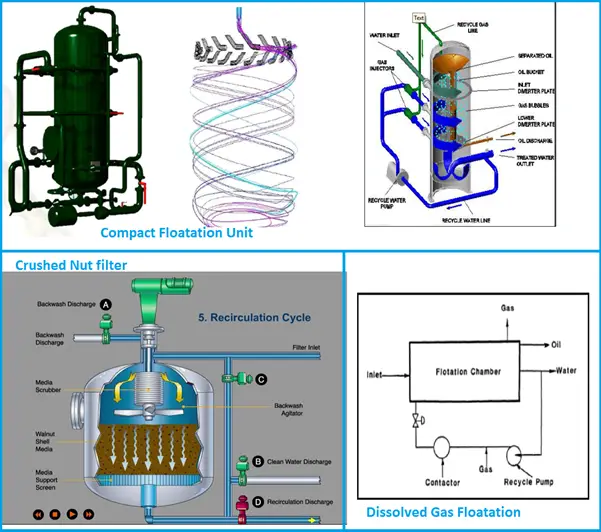
Produced Water treatment by Dissolved Gas Floatation(DGF-Fig. 7):
- Principle: Froth Floatation
- Description and Operation:
- Bubbles are generated by saturating a liquid stream with gas, typically at a pressure of 44 to 87 psig (3 to 6 barg).
- As the liquid enters the Flotation Chamber it is depressurized and the gas is released as fine bubbles.
- The rising bubbles attach themselves to hydrocarbon and float them to the water surface from where they can be removed by a skimmer and weir arrangement.
- The main advantage of DGF is that the method of producing bubbles is relatively gentle. The absence of the High Shear Forces helps in better separation.
Advantages and Disadvantages of Produced Water Treatment by DGF:
- Proven technology
- Moving parts and associated maintenance requirements
- De-oiling chemicals are normally dosed upstream to optimize performance
- Gas solubility decreases with increasing temperature which can make the technology less effective at higher operating temperatures
Compact Floatation Unit (Fig. 7):
- Principle: Froth Floatation and Cyclonic Effect
- Description and Operation:
- The CFU combines the swirling tangential flow effect of a hydro-cyclone within a gas flotation unit.
- The inlet fluid enters the vessel via one or more tangential inlets, establishing a mild rotation of the liquid in the vessel.
- Nitrogen or fuel gas is introduced into the vessel via a bottom distribution nozzle or “sparger” (there are some differences between vendors regarding how the gas is introduced into the vessel).
- The oil rejects from the vessel are normally removed via a central weir pipe at the top of the vessel.
Advantages and Disadvantages:
- The residence times in CFU’s are significantly lower than traditional IGF systems, with residence times of 1 minute being typical, compared to 4 minutes for IGF systems.
- Significantly smaller and lighter than conventional IGF
- Excellent turndown
- Normally requires a deoiling chemical to be dosed upstream to optimize performance
- Sensitive to vessel motion
Produced Water Treatment using Crushed Nut Filter (Fig. 7):
Principle: Hydrophillic Nature of Crushed Nut Shells
Description and Operation:
- Nutshell filtration involves the removal of suspended hydrocarbon liquids and solid matter from wastewater by passing the water through a bed of crushed nutshells(Typical-Walnut)
- The crushed nut shells have an affinity to hold the oil particles and the suspended particles.
- As the impurities are absorbed the media gets choked resulting in a higher pressure drop.
- This is an indication that the filter needs to be taken for backwash
- Once backwashed, it is again ready for filtration. To keep the process uninterrupted the filters are with N+1 configuration to take care of the capacity reduction during backwash.
Advantages and Disadvantages of Produced Water Treatment using Crushed Nut Filter:
- High-quality water effluent
- Very efficient for IW
- Removes TSS in addition to OiW
- The backwash mechanism is high on Energy and Maintenance
- Erosional issues due to the abrasive nature of media
- Large and heavy equipment
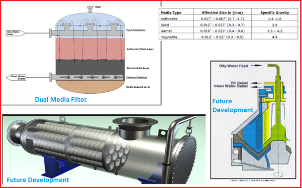
Use of Dual Media Filter (Fig. 8) for Produced Water Treatment:
Description and Operation:
- In a multimedia filter, two or more media with different grain sizes and densities are used.
- Within each layer, there will be size segregation with larger particles at the top and smaller at the bottom.
- The advantage is that this helps to minimize blockage and also maximize bed depth utilization.
- As the impurities are absorbed the media gets choked resulting in a higher pressure drop.
- This is an indication that the filter needs to be taken for backwash
- Once backwashed, it is again ready for filtration. To keep the process uninterrupted the filters are with N+1 configuration to take care of the capacity reduction during backwash.
Produced Water Treatment Future Development
- MEMBRANE FILTERS
- CENTRIFUGE
- CARTRIDGE FILTERS
- VENDOR SPECIFIC DESIGN
Excellent summary of various treatment steps. I have one comment: I think efficiency for walnut shell / sand filter is too optimistic. For removal of OiW down to the level mentioned, only polymeric coalesces with very fine pore structures which operate at very low fluxes can do the coalescence and separation of OiW at the level mentioned.
It would be good to share if you have data on current limits on OiW for overboard disposal in various parts of the world.
Thanks for sharing.
You PPM values are way off.
How is it possible that the water you are dumping (overboard discharge) is lower than that of re-injection. Maybe normal in India but not the rest of the world. It is downright pollution.
In the North Seal the overboard limit is 30 ppm, preferably lower. Our vessel gets down to below 20ppm.
Anup,
Hi, I’m Mark Guidry, I&E tech/programmer and new to production operating.
I have two questions.
* What thickness should the froth layer be?
* Should the froth be removed immediately leaving a clean water surface, or should a froth layer be maintained?
(wemco unit, mechanical gas induction ( agitator), paddle wheels for froth extraction).
Kindest regards.