Coalescer is a piece of important industrial equipment for the oil and gas industry used for liquid-liquid or liquid-gas separation from hydrocarbons. A coalescer uses its baffles or electric current to coalesce the small particles or droplets of hydrocarbons into larger ones and then separate them. This is also sometimes known as coalescing filter or filter coalescer. In this article, we will explore more about Coalescers or Coalescing Filters, their types, working, functions, and applications.
What is a Coalescer?
A coalescing filter or coalescer is an industrial device that separates fluid mixtures into individual components. Industrial process fluids contain various impurities like sulfur, ethane, carbon dioxide (CO2), water vapor, methane, etc. To maintain the quality of the final product, these impurities must be removed from the mixture. Coalescer plays an important role in separating these impurities from the mixture using the principle of coalescence.
What does it mean to Coalescence?
The term Coalescence means coming together or agglomerate. In the coalescence process, fluid molecules agglomerate to form a larger whole which is then separated as particulate components. This process is the reverse of the emulsification process.
What is the Function of a Coalescer?
The primary function of a coalescer is to separate mixtures or emulsions into their individual components using various methods. They can separate mixtures from homogenous or heterogeneous mixtures. A coalescing filter can be used independently or as a component of a larger separating unit. Coalescers are widely used as oil-treating equipment.
How does a Coalescer Work?
A coalescer or coalescing filter or filter coalescer consists of several baffle walls or screens located at different points inside the device. The mixture to be separated is then applied to the filter. The baffles of the separation device screen out the components by trapping them in different sections.
The screening mechanism works using the molecular weight and density of individual components. For example, in water-oil separation (liquid-liquid coalescer), the baffle walls present inside the coalescer separate the heavier oil molecules in one direction to a drain point. At the same time, the water vapor molecules diffuse through the filter element to agglomerate which is then drained out of the system gravitationally.
Similarly, in the case of gas-water separation, When the gas stream with water droplets is fed through the coalescer inlet, they diffuse through the filter element, and exit via an outlet port as dehydrated gas. The heavier water molecules coalesce to form larger water molecules and fall to the bottom of the tank for drainage.
Types of Coalescers
Depending on the working mechanism, there are two primary types of coalescers; Electrostatic Coalescers and Mechanical Coalescers.
Electrostatic Coalescers
Electrostatic Coalescers use AC or DC current or both. The water-in-oil emulsion is subjected to a high-voltage electrical field. If a non-conductive liquid (oil in the case of a water-oil mixture) containing a dispersed conductive liquid (water) is subjected to an electrostatic field, the conductive particles combine. There are three physical phenomena that may occur:
- The droplets tend to align themselves with the lines of electric force after becoming polarized by the electric current. In such a situation, the positive and negative poles of the droplets may be brought adjacent to each other. The electrical attraction between them brings the droplets together and causes them to agglomerate.
- Due to an induced charge, the droplets may be attracted to an electrode. Due to inertia in an AC field, small water droplets vibrate over a larger distance promoting coalescence. In a DC field, the droplets tend to collect on the electrodes, forming larger and larger drops and finally they fall by gravitational force.
- The film of the emulsifier surrounding the water droplets gets distorted and weakened by the electric field. When subjected to an alternating current field, the water droplets dispersed in oil will be elongated along the force lines during the first half cycle. During the low-voltage portion, when they are relaxed, the surface tension will pull the droplets back toward the spherical shape. In the next half of the alternating cycle, a similar effect is obtained. The weakened film is thus more easily broken when droplets collide, making coalescence more likely.
Using any one of the mechanisms, the electric field forces the droplets to move about rapidly in random directions, which in turn greatly increases the collision potential with another droplet to cause coalescence.
An AC current in the 50 – 60 Hz range is usually used for this purpose. Electrostatic coalescers find extensive applications for separating water-fuel emulsions in offshore oil and gas production facilities.
Mechanical Coalescers
As mentioned earlier, mechanical coalescers work by employing a series of filter elements or barriers for separation. In a mechanical coalescer, the water droplets are intercepted by the barriers. On the other hand, the oil gets thinned by the baffle fibers while passed through them. In the process, the water separates out from the oil. A plate coalescer is a typical example of a mechanical coalescer.
Plate Coalescers:
Plate coalescers are available in various configurations. These are commonly known as parallel plate interceptors (PPI), cross-flow separators, or corrugated plate interceptors (CPI). The working principle of all plate coalescers depends on gravity separation to allow the oil droplets to rise to a plate surface where coalescence and capture occur.
As shown in Fig. 1, flow is split by a number of parallel plates spaced 0.5–2 inches apart. The plates are sometimes inclined horizontally. It promotes oil droplet coalescence into films which guide the oil to the top for entrapment into channels, thereby preventing remixing with the water. The plates provide a surface for the oil droplets to collect and for solid particles to settle.
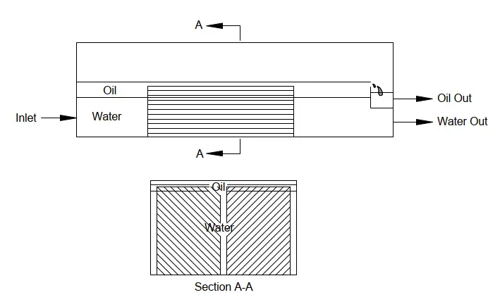
Plate separators are recommended when:
- There is a steady water flow rate.
- Size and weight are not constraints.
- Solid contaminants are not significant in the waste stream, and sand content is less than 110 ppm.
- To periodically clean the plate packs, Utilities and equipment are available.
- Influent oil content is high and oil concentration must be reduced to 150 mg/l for effective second-stage treatment in a downstream unit.
Plate separators are not recommended when:
- Size and weight are the primary considerations.
- Influent droplet sizes are below 30 mm.
- Sand particle diameters are less than 25 mm, and solids removal is a primary objective.
Depending on which product the coalescer separates out, coalescing filters are categorized into various types like:
- gas coalescer
- oil coalescer
- natural gas coalescer filter
- fuel coalescer
- condensate fileter coalescer, etc
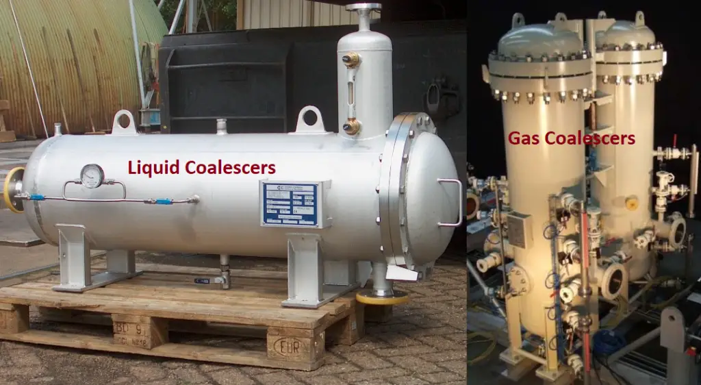
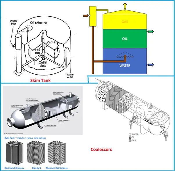
Fig. 2 below shows a typical example of liquid and gas coalescers used in the oil and gas industry.
Applications of Coalescers
Coalescers or Coalescing filter separators are employed for a wide range of applications in the downstream oil and gas, petrochemical, and chemical industries for liquid-liquid or liquid-gas separation.
Downstream Operations: In downstream oil and gas, coalescers find applications for refining the products. At natural gas refineries, coalescing filters are used to de-humify natural gas to ensure product quality and purity. Also, in a gas-oil coalescer system, coalescers purify the natural gas by eliminating condensate and several natural liquids.
Again, coalescers have the capability to prevent the corrosion of compressors, amine/glycol absorbers, turbines, and membrane filtration systems by removing corrosive contaminants like sulfur, water vapor, etc.
For recovering lube oil from a compressor, Coalescing filters are installed at the compressor inlet. Fluids that are fed into the compressor inlet usually have a particulate matter, aerosols, dissolved hydrocarbon liquids, and slugs. To improve compressor performance and recover the oil these are extracted using a coalescer placed upstream of the compressor.
Petrochemical Industries: For phase removal of water vapor, amine solutions, and sulfur from petrochemical feedstock prior to storage, Liquid-liquid coalescers can be used.
Coalescer Design
A coalescer has a vertical or horizontal configuration. The parameters that affect the design of a coalescer are process requirements, safety, and economics. The following parameters must be decided prior to coalescer design:
- The minimum, average, and peak flow rates of Gas and liquids.
- Operating and designing temperatures and pressures.
- Feed stream surging or slugging tendencies.
- Density, viscosity, and compressibility of the fluids.
- The required degree of separation
What is the difference between a Filter and a Coalescer?
The main difference between a filter and a coalescer is that a filter normally separates a solid particle from gas or liquid whereas a coalescer provides the separation of two phases.
What is an Oil Coalescer?
An oil coalescer is a filtration system that removes gasoline, diesel, non-emulsified oil, and fuels from a waste stream. Closely spaced oil-attracting media is used in the oil coalescers to promote agglomeration of larger oil particles, which then flow up the surface.

Hello Kumar. I have a question, regarding the design of this filters.
For the associated piping of a gas coalescer filter for example, does B31.3 applies? Or B31.8, assuming that the filter is located inmediatelly downstream a pig receiver?
And for associated piping I mean drain, vents, control lines.
share relevant infomation