
Carbon steel piping with internal PE / ROTO lining is used for liquid service with high chloride as well as higher oxygen content. The maximum operating temperature of the PE & ROTO lined piping is 60 °C. Also, these types of coatings are suitable for gas-liquid ratio values up to 300.
A PE liner consists of a number of Polyethylene pipe lengths, which are fused together and inserted into sections of carbon steel pipelines and flowlines. The Carbon Steel pipe provides pressure containment; while the PE liner provides corrosion protection. At the ends of the sections, the liners are terminated by PE stub ends. Connections between PE-lined carbon steel pipes shall be flanged.
The PE & ROTO lining is carried out only after the pipe spools are fabricated & hydro-tested. No welding is allowed on the pipe spool once the PE or ROTO lining is done. The pipe trunnion member & line stop members, if applicable, shall be welded prior to the lining. Hydrotesting of the spool or pipelines is done before the lining & after the lining also. Therefore, gaskets are required to be considered for each flanged joint for hydro test purposes.
The requirements to be considered while designing PE-lined piping are mentioned below:
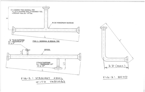
PE/ROTO lining dimensional limitations:
The longest continuous length of liner, which can be installed in straight pipe, depends on diameter and wall thickness but is generally reduced in practice by local curvature of the line.
For off-plot piping scope, the PE lining can be done for a pipe spool of up to 250m lengths. For shop-lined piping, the maximum length of PE lined pipe spool is kept at 18m because of transportation limitations. The minimum pipe spool length requirement is 5m (can be as less as 2m if agreed with the PE lining vendor). PE lining can be done only for straight pipe spools. It can not be done for pipe spools with reducers or branches. In such cases (for pipe spools with reducers or branches) roto-lining is carried out.
Bends for PE lining shall not be less than 20D radius (recommended radius is 40D wherever possible). PE or ROTO lining cannot be carried out for pipe spools with orifice flanges because of the small size of orifice flange tapings. In this case, one option is to use a suitable material for the upstream & downstream pipe spools & the orifice flanges. And the other option is to use carrier rings with orifice tapings & orifice plates of the suitable material which will get sandwiched between two PE-lined flanges and avoids the use of expensive material for the upstream & downstream pipe spools.
Annulus Vents
Every PE-lined pipe spool shall have vent points. The minimum number of vent points shall be one on each flanged end of a section of lined pipe. The vent points are to be provided with valves for oil & gas applications & without valves for water service applications. The valves shall be opened only for venting purposes. Continuous venting is not permitted. The purpose of venting is as follows.
- To vent the (ambient) gas from the pipe/annulus during installation.
- To vent the permeated fluids accumulated in the annulus to prevent collapse.
- To allow monitoring of the integrity of the PE liner during the service life.
Vent holes shall be designed such that no extrusion of the PE liner will occur. For larger diameter lines, vent discs with multiple holes or wire screens may be used. Vent holes shall not be larger than 3 mm in diameter. All vents shall be valved (except for water service where vents can be plugged) and shall have a “snorkel” to prevent ingress of dirt, moisture, and/or air.
The design of the vent point assembly shall be agreed upon with the Company.
Design Guidelines for ROTO Lined Piping
Rotolining is a method of lining the inside of pipes or other parts with a seamless, one-piece inner layer of plastic. In this lining technique, the lined spool is produced by heating and rotating a carbon steel spool with a polymer, which is in a granular form, placed inside the pipe spool. The polymer melts and forms a liner on the internal surface of the carbon steel pipe. Also, the polymer forms a bond with the metal.
The choice of which polymer to use is based on the chemical resistance properties that are required for the final part. Polyethylene, Polypropylene, PVDF, or a number of other polymers is used for roto-lining applications. The lining thickness varies from 2 mm to 8 mm. The heavy lining thickness allows the post-machining of critical surfaces that would not be possible with a thinner lining applied by other methods. Virtually any type of metal weldment or casting can be rotolined. Typical items that can be rotolined are tanks, carbon steel pipes, fittings, and complex welded structures.
Rotolining Procedure
The rotolining process comprises placing a polymer having an average particle size of 70-1000 μm containing a melt processible fluoropolymer, in a cylindrical article to be lined (the powder being present in a sufficient amount to make a lining at least 500 μm thick).
The cylindrical article is rotated to bring the radial acceleration at the substrate surface to be coated to 100 m/sec2 or greater, pressing the powder against the article to be lined by means of the centrifugal force generated by that rotation, at the same time heating the melt-processible fluoropolymer to a temperature equal to or higher than the melting point of the melt-processible fluoropolymer, but not higher than 400° C., thereby adhering the melt-processible fluoropolymer to the surface of the article to be lined.
During the heating cycle, the polymer particles begin to stick to the hot metal substrate. Skin is formed. This skin gradually forms a homogenous layer of uniform thickness. Ultimate wall thickness is determined by the amount of material that is initially placed into the cavity.
Adding a small amount of a heat stabilizer such as PPS (polyphenylene sulfide) to prevent the decomposition of the fluoropolymer on heating can give an excellent coating with minimal bubble formation.
After a predetermined time at a specific temperature, the entire polymer is distributed over the surface of the spool. The spool is then cooled by a combination of forced air and water mist.
The part is then removed from the machine and surfaces such as the flange face and “O” ring sealing areas are machined into the plastic. Linings are spark and ultrasonically tested to ensure liner integrity.
The process itself introduces no force or shear to the material. The result is a relatively stress-free lining. Rotolined parts are completely seamless and weld-free.
Advantages of ROTOLINING
- Seamless construction with a very smooth interior surface.
- Polymer rotolining has excellent chemical resistance, relatively high-temperature performance, and an excellent metal-to-plastic bond.
- Thicker lining & uniform wall thickness can be achieved than electrostatic or spray coating.
- Drastically reduces permeation through the coating and possible corrosion of the metal substrate.
- The thicker coating can be repaired by welding if mechanically damaged. Thin coatings must be stripped and recoated if repairs are not possible.
ROTO lining dimensional limitations
Guidelines for ROTO lining dimensional limitations are as per below table:
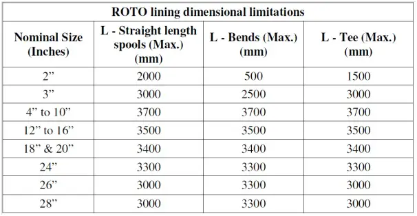
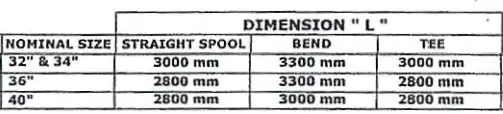
All dimensions given in the above table shall be considered diagonal lengths. The above dimensions shall be verified with the ROTO lining contractor prior to issuing the isometrics for fabrication.
For ROTO lining minimum branch-off size shall be 1” NB.
The thickness of PE & ROTO lining on the flange raised face (collar thickness) is as per the below Table:
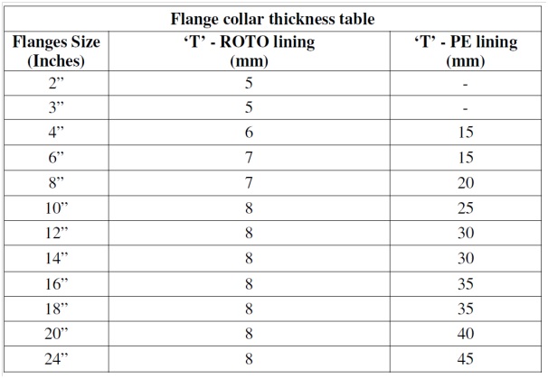
The above thicknesses shall be verified with the PE & ROTO lining contractors prior to issuing piping isometric drawings for construction.
Flange joint details for PE / ROTO lining piping:
Typical PE / ROTO lined flange joint detail is as follows:
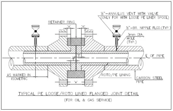
The 1/2” NB annulus vents shown in the above sketch are for PE-lined pipe spool only.
Galvanized carbon steel retainer rings are used between PE / ROTO lined flange joints to hold the stub ends in place (to avoid the plastic material from deformation). The width of the retainer ring is calculated as follows:
A = (2 x B + 2 x T) – 3 mm
Where,
- A – Width of the retainer ring
- B – Thickness of flange raised face
- T – Collar thickness
Retainer rings are generally provided by the PE lining vendor, still, it has to be confirmed with the vendor at the start of the project.
The following sketches provide information regarding the use of a retainer ring & insulating gasket for PE & ROTO lining flange joints.
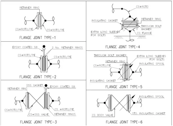
The use of insulating gasket for PE & ROTO lining piping is restricted for the insulating spools only wherever shown in P&ID/PEFS. For a flange joint between PE / ROTO lined CS piping & SS or DSS mating flange insulating gasket is not required to be provided.
For insulating joint insulating gasket, extra long sleeves, washers & extra long bolts are required. The spectacle blind, spade & spacers shall be considered suitable material for PE & ROTO lined piping and the blind flange shall be epoxy coated or ROTO lined. This shall be finalized with the client & construction contractor prior to the start of a project.
A typical isometric of PE/Rotolined pipe is shown below:
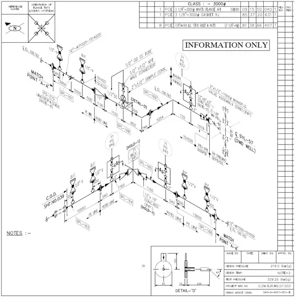
Information provided can be considered as guidelines only…Flange thickness ‘T’ Table value changes and can’t be standardized as mentioned because it’s depend on liner design w.r.t operating temperature, medium (water / crude), collapse pressure, type of lining technique (Titefit / partially loose etc). Also, the same will be applicable for connection Rings as they changes based on ‘T’, flange rating and compression value of HDPE material.
Hi Anup
I work for an oil operator and found your article very useful for a current personal biz startup in piping and pipeline integrity, please get in touch to discus more.
very good,precise content. 🙂
Good Information but I have some clarification need to be cleared from this article. Minimum pipe spool length can be pulled is 5M. Which standard says this?
hi there
Informative article. it’s very helpful for beginners.
Thanks for sharing the knowledge about Guidelines for PE or ROTO lined carbon steel piping. well done keep sharing.
Thankyou your article helped me.
Hi Anup,
Thanks for the information. I am working in the Sustainability Domain, performing the life cycle Assessment of the products so as to quantify the carbon footprint. It would be great help if you can help me by suggesting some papers where I can find the inventory associated with the manufacturing of carbon Steel pipe having thermoplastic liners. ( i.e. the ratio of Carbon Steel with HDPE(lets say) for 1m of pipe produced.)
I am really looking forward to your support
Hi Anup,
In case of steel pipelines internally lined with HDPE liners, Could you please confirm the need of flanges if there is a variation of pipeline thickness due to crossings.
I am looking forward to your answer.