
Before connecting the process gas piping with compressor nozzles, the shaft alignment work for the compressors and driver shall be carried out to ensure their concentricity. This concentricity between the shaft and the driver is very important for the proper smooth working of the compressors. This article will explain the alignment methodology in brief.
Concentric Alignment
Stainless steel shims 3 mm thick shall be placed equally beneath the legs of compressors to be erected on the baseplate, and then the equipment shall be placed on the baseplate. This is applicable when compressors are separately shipped from the baseplate. Thereafter, each fitting bolt is tightened. Alignment shall be concentrated through the equipment closest to the driver by adjusting the shim thickness beneath each piece of equipment.
The alignment work shall be carried out from place to place according to the specified order. In this step, the alignment of all equipment shall be concentrated first on the adjustment of the shims so that the equipment falls within the tolerance specified in the cold alignment map.
Final Alignment
The driver and all powered equipment shall be aligned at a cold offset position considered normal for operation. The specified values of cold offset are met by means of increasing or decreasing the thickness of the shims beneath the legs of all equipment from the concentric alignment position.
Once all the equipment satisfies the specified values, it is necessary to prepare an accurate alignment map between the equipment concerned and to record the shaft distances and thicknesses of the shims beneath the legs. After the cold offset alignment is completed, record and file the alignment data, shaft distances, and shim thicknesses.
These records will serve as important data for correcting alignment in the future. The allowable misalignment under the above cold offset condition shall be within +/- 10/100 mm of the planned alignment value
Hot Alignment
If any problem such as high vibration occurs, hot alignment checking will be only effective and helpful as a troubleshooting aid and/or for finding the appropriate countermeasures to take. It is not recommended hot alignment checking by using dial indicators on coupling hubs or anywhere else after a few hours or more of running, because the temperature of the equipment will change very quickly after shutdown.
Typical operational experience data for the best hot alignment are as follows:
- Vertical thermal expansion growth of all equipment shall be calculated based on actual temperature measurement at supports under normal operating conditions.
- If optical alignment equipment and material are available, they will be used for checking the alignment under cold conditions and normal operating conditions.
Shaft Alignment method/Steps
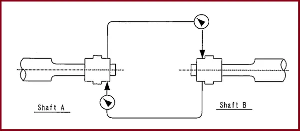
- Install the alignment jig also known as the Alignment fixture to shaft B and attach the dial indicator to the jig as illustrated in Fig. 1.
- Turn Shaft B Once to check for normal contact between the dial indicator on Shaft A.
- Slowly turn shaft B and take four readings at every 90 degrees (Refer to example 1 in Fig. 2)
- Then turn Shaft A by 180 degrees, then with Shaft A at this position, turn Shaft B once to check for normal contact with the dial indicator on Shaft A. then bring a dial indicator at the top of the shaft and set it at zero.
- Slowly turn Shaft B and take four readings every 90 degrees. Please bear in mind that the indicator reading at each 180-degree position on Shaft A (point 4) is important for correcting the runout of the coupling.
- Remove the alignment jig from Shaft B and attach it to Shaft A. Set the dial indicator above shaft B and perform the same measurements as mentioned above (Refer to Example 2 in Fig 2)
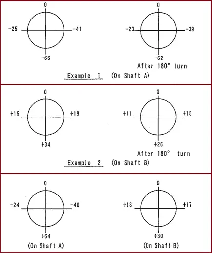
If the readings are such as those shown in Fig. 2 last image, the alignment of Shaft A and of Shaft B is the arithmetical mean of each of the two corresponding figures.
The alignment jig used for this must be free of any deflection to minimize measurement errors.
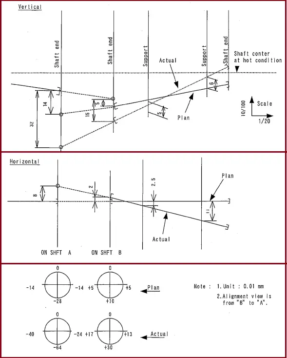
Preparation of Alignment Map
Depict the position of the rotor, the driver supports, and driven equipment such as the steam turbine, and the compressor in a reduced scale on graph paper and plot measurements on it. By this graph, one can easily find the present position of each rotor and the thickness of the shims to be used for adjustment. (Refer to fig. 3)
Few Notes
- The final alignment before connecting the process gas piping shall be carried out in accordance with the cold alignment map issued by the vendor.
- If an unallowable misalignment exceeding the cold alignment map limitation is observed, correction shall be made by adding or removing the shims beneath the compressor leg supports.
- During the alignment work, the distance between shafts shall be measured often and checked within a tolerance of +/-0.5 mm. If it exceeds the limitation, a re-adjusting shall be made by moving the compressors.
- While the shaft end distance is measured, each shaft should be moved towards the active side thrust bearing to put it at the expected operating position.
Few more Useful Resources for you..
Shaft Alignment Methodology for Compressor and Driver
Connection procedure (Alignment) of Process Piping with Rotating Equipments: An Article
Alignment Check Methodology in Piping Stress Analysis using Caesar II
Few articles related to Pumps
Piping Design and Layout Basics
Thanks you