
Process P&ID is the most important multidisciplinary document produced for any oil and gas project. The majority of the piping design information is taken from the piping and instrumentation diagram while laying a piping system. Every P&ID contains lots of piping information and hence P&ID is the piping designer’s roadmap for laying out the piping system. Some of the terms used in P&IDs are quite confusing to piping engineers and designers. Four such widely used terms are:
- No Pockets
- Free Draining
- Slope
- Gravity flow
In this article, we will explain the meaning and requirements for No Pockets, Free Draining, Slope, and Gravity flow in piping system design. Let’s have a quick walkthrough of all the above requirements with examples.
No Pocket
Definition of No Pocket
The term “NO POCKET” means no liquid pocket in the line. When it’s necessary to prevent vapor pockets, the note will read “NO VAPOR POCKETS”.
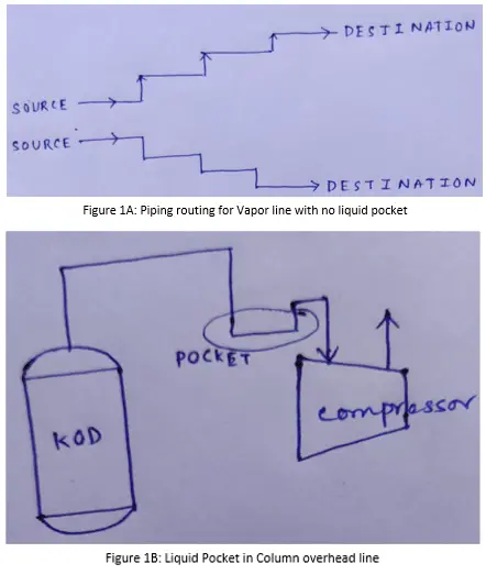
For “NO POCKET” lines elevation changes are either vertically up or vertically down, but not both. Refer to Figure 1A.
What is Pipe Pocket?
A section of the pipe that will not self-drain due to pipe layout/orientation is considered a “pipe pocket” (refer to Figure 1B).
Why Do Pockets Appear?
- During piping layout, pipes may encounter many obstructions (Such as Structure, Equipment, other piping, etc) and may need to change elevation.
- Valve accessibility
- Expansion loop
P&ID representation of No Pocket
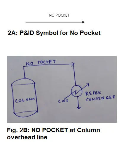
In P&ID, the no pocket is indicated with an arrow as shown in Fig. 2A below.
Typical applications of No-Pocket
- Two-phase lines,
- Compressor suction line,
- Column overhead vapor lines,
- Vapor balancing lines, etc.
Examples of No-Pocket Lines
The column overhead vapor line going to the overhead condenser, should not have a liquid pocket, this is the minimum requirement. If the column overhead vapor carries entrained liquid it may accumulate in this liquid pocket and prevent the free vapor flow by plugging the flow path. This liquid accumulation may not be apparent until upset (flooding, product quality deviation, etc) occurs. So, rather than depending upon signals and low point draining, piping can be routed in such a way that prevents any liquid accumulation. That’s why we indicate “NO POCKET” for the column overhead vapor line in P&ID (refer to Figure 2B).
For a Two-phase flow line, Process engineers typically indicate a note “Provide support for two-phase flow”. Typically, they try to minimize the slug flow regime in the two-phase flow because that can lead to serious pressure fluctuation and vibration. A two-phase flow line should not have a pocket, because liquid will accumulate and promote unstable flow.
The pump suction line should not have any high point vapor pocket (NO VAPOR POCKET). However, this is typically not specified on P&ID.
Free Draining
Definition of Free Draining
The term “FREE DRAINING” means elevation changes are downward only for the unwanted liquid to drain out from the line (process motive fluid may have a different flow direction). No pockets (no liquid and gas pockets in the line) are permitted. A free draining line may or may not be sloped (Refer to Figure: 3A)
The line does not need to be sloped, but it must not be pocketed. Any line with a “FREE DRAINING” note towards any equipment or low point indicates undesirable liquid flowing towards the lower point. “FREE DRAINING” with directions towards equipment is covered with no pocket requirement also. “FREE DRAINING” with direction is typically to empty out or clean the line from undesirable liquid accumulation. The direction of the main process fluid flow may or may not match the direction of “FREE DRAINING”.
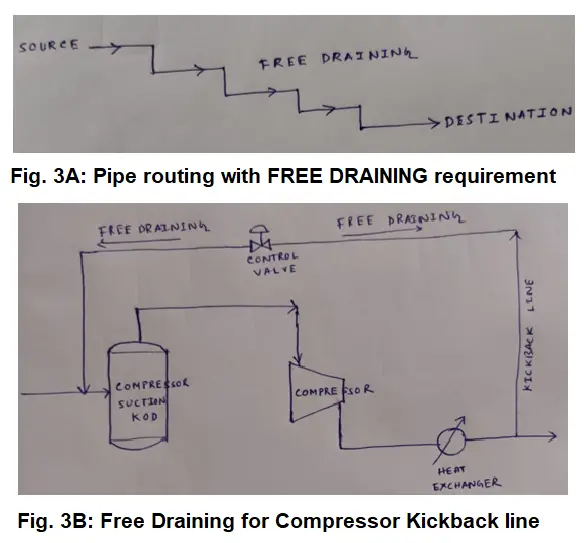
For example, Compressor Kickback lines. To prevent liquid from obstructing kickback operation, the vapor kickback line (vapor mainly flows from the compressor discharge side to the suction side) upstream of the control valve should be free draining to the inlet line of suction KOD and downstream of control valve free draining to a low point at discharge line. This can be achieved by elevating the kickback valve above the drum’s maximum liquid level (refer to Figure: 3B).
P&ID representation
The P&ID symbol for free draining is similar to the No pocket P&ID symbol. Here also the term No Pocket is mentioned above the arrow.
Typical applications:
PSV inlet/outlet line, Dead leg, Compressor suction line should be free draining towards suction KOD, Compressor kickback line, etc.
Examples of Free Draining Lines
The relief valve inlet line shall be free draining towards the protected equipment or Pipe header where it’s installed. Relieving fluid flow goes upward and relief through PSV, but any liquid at this line will be free draining towards protecting equipment to ensure no liquid accumulation that can hinder relief operation.
The relief valve outlet line (tail pipe) should be free draining towards the Flare header or Flare KOD. Refer to Figure 4A.
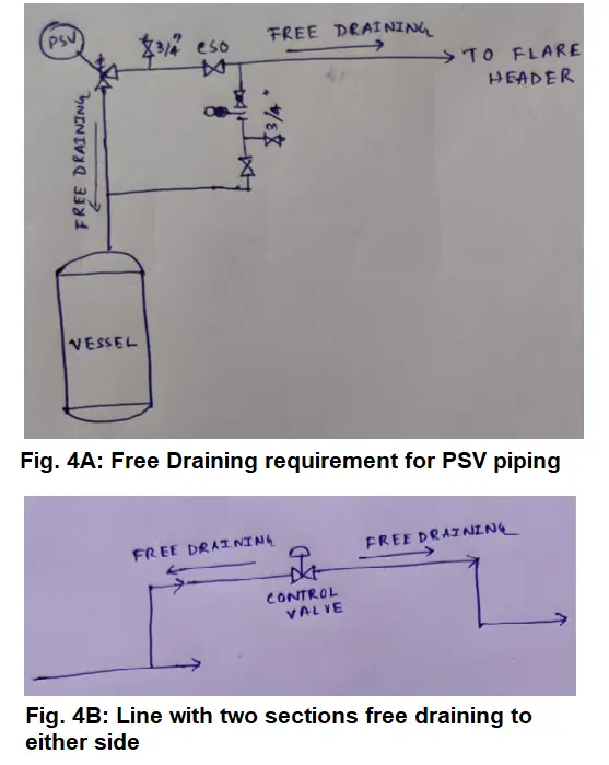
A line can have two sections free draining to either side as shown in Fig. 4B. Compressor suction pipe should be free draining towards suction KOD or low point in the suction line.
Slope
Definition of Slope
The slope indicates a change in the elevation of the line. In general, slope indicates elevation changes that are constantly downward. Slope requirements are specifically mentioned in the P&ID using symbols.
P&ID Symbol for Slope

In the piping and instrumentation diagram, the slope is represented as shown in Fig. 5. In this Figure, X has a unit the same as 1. In general, they are given as (SLOPE is mm: mm)
Typically, a minimum 1:500 slope is required for Flare main header and 1:200 is required for Flare sub-headers.
More details about the piping slope can be found here.
Typical Applications of Slope
Typically, the following lines are provided with slope:
- Flare main header,
- Flare sub-header,
- Drain header,
- Stormwater channel, etc.
Gravity Flow
Definition of Gravity Flow
Gravity flow means that the elevation downstream never exceeds inlet elevations. The line may contain pockets.
P&ID Symbol for Gravity Flow
In P&ID the gravity flow requirement is represented by using a symbol to the Free draining requirement symbol. This means here also, the term Gravity flow is mentioned above the arrow.
Typical Applications of Gravity Flow
Sometimes we have a stacked design in such a way that column will be at the bottom section, Exchanger (Reflux condenser) will be at the top, and the reflux drum in between the column and exchanger. For those configurations typically we don’t use the pump for reflux going to a column. We making sure that the reflux will flow by gravity to the drum because of the elevation difference. And from the drum, it flows to the column using gravity. There we typically indicate gravity flow. Because of the elevation difference between source and destination, process fluid flow by gravity, there we are not using any pump. The gravity flow line is not the same as free draining.
Free draining is typically for cleaning lines purposes whereas Gravity flow (direction of process motive fluid has the same direction) occurs because of elevation difference.
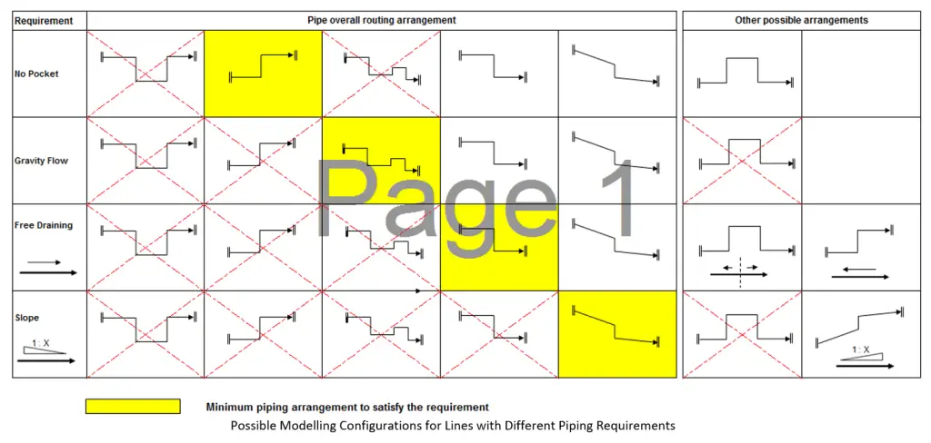
Fig. 6 (Image Courtesy: https://www.linkedin.com/pulse/slope-free-draining-gravity-flow-pocket-jargon-saeid-rahimi-mofrad/) below depicts some of the acceptable piping arrangements that can be used by piping designers for the correct interpretation of P&ID piping requirements into the 3D model.
So informative! Miss Mukherjee, the writer has left no stone unturned to explain all the vital concepts with simple handmade diagrams. Even a layman can understand what is the article about. Well written piece loaded with hardwork.
Thank you.
KINDLY share detail about both side slope