
What is the Tee branch connection?
A tee branch connection is a type of piping fitting that allows for the branching of a pipeline into two or more directions, typically at a 90-degree angle. This configuration resembles the letter “T,” hence the name. Tee branches are essential in various fluid transport systems, including water, gas, and oil pipelines, as they enable the distribution of fluids to multiple locations from a single source. The design ensures that flow can be redirected efficiently while maintaining pressure and minimizing turbulence, which is crucial for the system’s overall performance.
Importance of Tee Branch Connection
The importance of tee branch connections lies in their ability to facilitate complex piping layouts without compromising flow integrity. They are commonly used in industrial, commercial, and residential applications, allowing for flexibility in system design and maintenance. By enabling multiple connections from a single pipeline, tee branches optimize resource utilization, reduce material costs, and streamline installation processes. Properly installed tee connections also contribute to system reliability, helping to prevent leaks and other operational issues that could arise from improper flow management.
This article provides guidelines for modeling tee or branch connections using software START-PROF. The guideline covers modeling for both the Standard Tee and Non-Standard Tee Connection.
Modeling Standard Tee
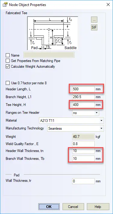
When you create a standard tee in START-PROF, you can specify tee length (L), tee height (H), header wall thickness, and branch wall thickness.
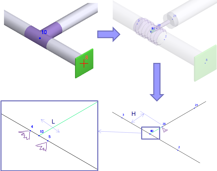
When you run analysis simple tee model is automatically replaced by a complex model. Added 6 additional nodes (21, 2, 3, 4, 5, 20). Nodes are hidden for the user. It is visible only in developer mode.
- 10-20 Element is rigid (H=Dh/2, Dh – header outer diameter)
- 4-10 and 10-5 elements length is 1 mm (L=2mm)
- 20-21 pipe element has a wall thickness specified in “Tee” dialog box Tb=10 mm. It can be thicker than the connected pipe
- 4-3 & 5-2 pipe elements have a wall thickness specified in the “Tee” dialog box tn=10 mm. It can be thicker than the connected pipes
Modeling Non-Standard Tee
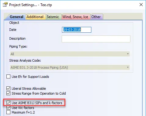
For “Nonstandard Tee” and for any standard tee if ASME B31J code is selected, additional run flexibilities are added into nodes 4 & 5, and branch flexibilities are added into node 20. Flexibilities calculated according to ASME B31J
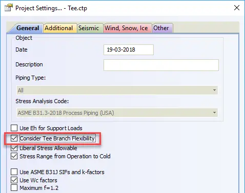
If the option “Consider Tee Branch Flexibility” is selected, then 4 & 5 nodes are not created for standard tees. The flexibilities in node 20 calculated according to ASME BPV SIII div 1 class 1 NB 3686.
Few More Resources for you…
Piping Stress Analysis using Start-Prof
Piping Stress analysis Basics
Piping Stress Analysis using Caesar II
Piping Stress Analysis