Slug flow is a phenomenon that occurs in multiphase flow systems, particularly in pipes and pipelines carrying gas and liquid phases. It is characterized by the intermittent presence of large, cohesive bubbles or slugs of gas that travel through the liquid. This type of flow can lead to significant operational challenges, making slug flow analysis crucial for engineers and operators in industries such as oil and gas, chemical processing, and water treatment.
The purpose of this article is to explain the slug flow in piping and the static analysis of the piping system having slug flow using Caesar II. One of the major causes of piping vibration in operating plants is slug flow. So, it’s always preferable to design systems to overcome the effects of slug forces.
What is Slug Flow?
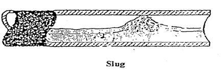
Slug Flow is a typical two-phase flow where a wave is picked up periodically by the rapidly moving gas to form a frothy slug, which passes along the pipe at a greater velocity than the average liquid velocity.
In this type of flow, slugs can cause severe and, in some cases, dangerous vibrations in piping systems because of the impact of the high-velocity slugs against fittings such as bends, tees, etc.
Characteristics of Slug Flow
Intermittency: Slug flow is marked by intermittent movement of gas bubbles within the liquid. These bubbles can merge to form larger slugs, causing a non-uniform flow.
High-Pressure Fluctuations: The movement of slugs can lead to pressure surges within the pipeline, which may damage equipment and create safety hazards.
Liquid Hold-up: During slug flow, there is a significant amount of liquid held up in the pipeline, which can impact the overall efficiency of the transport system.
Flow Regime Transitions: Slug flow can transition into other flow regimes, such as annular or stratified flow, depending on changes in flow rates or other conditions.
Is Slug Flow Dangerous?
Slug flows generate dynamic fluid forces, which may induce structural vibration.
Slug Flow
Excessive vibration may lead to component failures due to fatigue or resonance. Other reasons for worrying about Slug Flow are
the liquid trapped in the pipeline in low spots due to imbalances in the distribution of gas and liquid phases.
a flow rate change.
pipe geometry change
Pigging
significant density differences, etc
Such vibration problems may be avoided by thorough analysis, preferably at the design stage. Two types of Analysis Methods are prevalent in piping design-
Process Engineers will Analyze the two-phase flow regimes and inform accurately whether the given fluid can cause slug flow while flowing through the piping system. On a broad scale normally following lines are believed to give slug tendency.
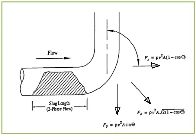
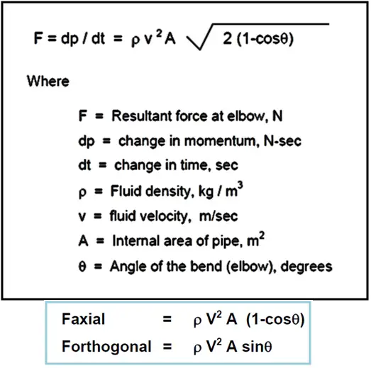
Slug force is equal to the change in momentum with respect to time. The equation used for the calculation of slug forces is provided in the attached figure:
Diagram Showing Applications of Slug Force
Use the following equations to calculate the Slug Force.
Multiply the calculated value with a suitable DLF. Normally a DLF of 2.0 is common to use.
Diagram Showing Slug Force Equation
From the above slug force calculation equation it is quite clear that:
The value of slug force will increase with an increase in fluid density
The slug force is directly proportional to pipe size; with an increase in pipe size, the resultant slug force will increase.
The calculated slug force is directly proportional to fluid velocity, which means with an increase in fluid velocity the impact of slug force will increase.
Also, the magnitude of slug force is directly proportional to the momentum flux (Rho X A X V2)
Alternate Equation for Slug Force Calculation
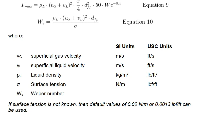
Alternatively, you can use the following slug force calculation equation as provided in Shell DEP 31.38.01.25, Feb 2023. As per clause 2.2.7, point no. 7 of the mentioned DEPs,
Slug flow piping system shall be designed to accommodate the reaction forces and vibration fatigue. The maximum reaction force Fmax shall be calculated in accordance with Equations 9 and 10.
Slug Force Calculation Formula as per DEP
Static Analysis of Piping Systems Carrying Slug Flow
Inputs Required for Static Slug Flow Analysis
Stress isometrics of the complete system.
Line parameters such as line temperatures, pressures, fluid density, pipe material, corrosion allowance, insulation thickness, density, etc.
Parameters required for Slug force calculation like slug density or liquid density, two-phase velocity, etc.
While performing slug flow analysis the following two assumptions are made
It is assumed that the slug is formed across the full cross-section of the pipe for maximum impact. This configuration is least probable for vertically down word flow as no hold–up is possible for the accumulation of liquid and eventual formation of the slug. Hence slug force at elbows for vertically downward flow lines is not considered.
It is assumed that the reader knows the normal static analysis of the piping system using Caesar II.
Sample Case Study for Slug Flow Analysis in Caesar II
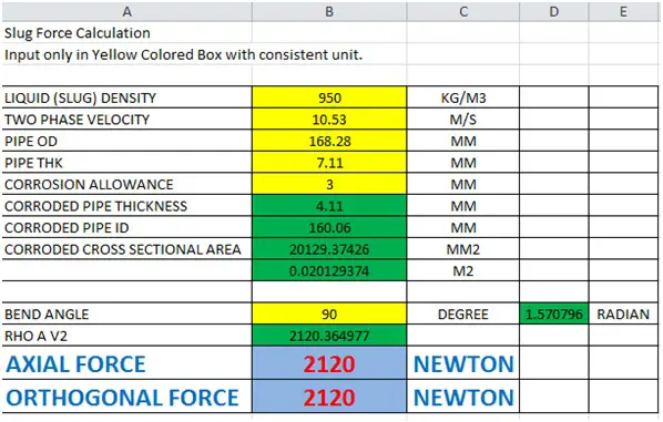
Let’s assume the shown system is subjected to slug flow. The parameters for the pipe are as mentioned below:
Pipe: A106B, 6”, Sch 40
CA=3 mm
T1=100 degree C
T2=75 degree C
P1=15 bar
Liquid Density=950 Kg/m^3
Two-phase Velocity=10.53 m/s
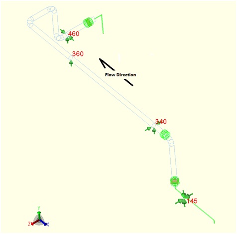
Stress System under consideration
After modeling the piping system following the conventional method, we have to calculate the slug force and apply the same to the system. Normally all organizations have their Excel spreadsheet to calculate Slug Force. A typical Excel spreadsheet for slug force calculation is shown in the below-attached figure for your reference.
Excel Spreadsheet for Slug force calculation
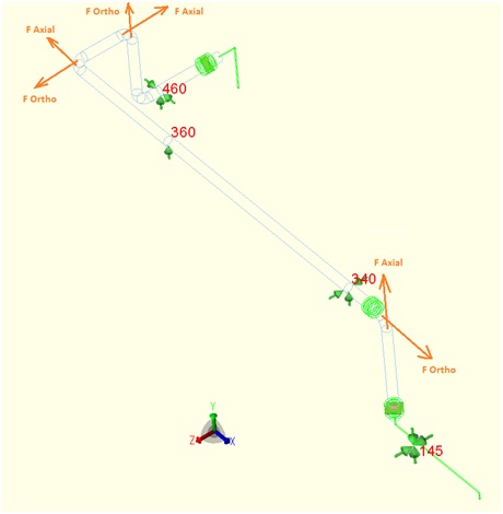
So if we use a DLF of 2 then each axial and orthogonal force will be 4240 N. We have to incorporate this force in the Caesar II input spreadsheet. Check the below-mentioned figure for the direction of forces.
Slug force in Bends with Application direction
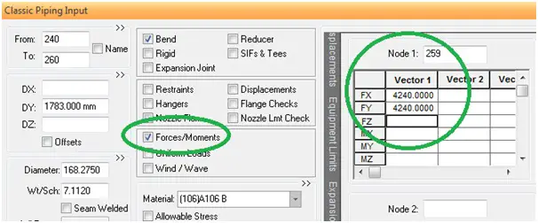
Now we will input the axial and orthogonal forces at all changes in direction as shown in the attached figure.
To enter forces click on the Forces button in the Caesar II spreadsheet.
Provide the node number and magnitude of forces with the proper direction.
Similarly input forces in all bends (other than vertically downward bends).
Caesar Spreadsheet Showing input methodology of Slug Force
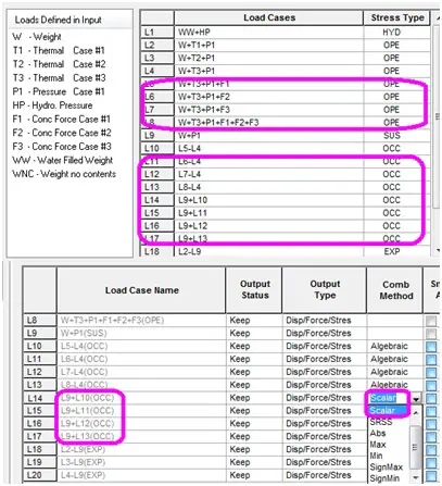
The next step is to prepare the required load cases. Some additional load cases need to be prepared for static analysis of slug force. The same is shown in the figure below.
Caesar II Load cases for Slug Flow Analysis
Prepare the load cases as mentioned in the figure.
Make stress types occasional
Use combination methods such as Scalar
Understanding the Slug Flow Analysis Output
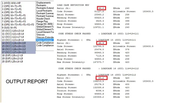
Additionally, We have to check code compliance for load cases L14 to L17 and ensure that the values are well within code allowable values.
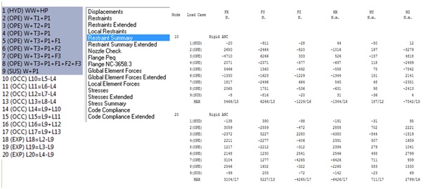
We have to check forces and displacements for load cases L1 to L9.
Refer to the below-mentioned figures for reference:
Caesar II Code compliance check report
Caesar II Restraint Summary check report
Keep all stresses, forces, and displacements within the allowable limit. If exceeds then try iteration with the support location change, support type change, or pipe routing change.
Slug Flow Prevention/ Mitigation
To effectively mitigate the risks associated with slug flow, a variety of preventive measures can be adopted. Here are some essential strategies for prevention:
1. Optimized Pipe Configuration
Designing the piping layout to minimize the potential for liquid accumulation is crucial. This includes avoiding configurations that create pockets where liquids can be collected. A well-thought-out design can significantly reduce the likelihood of slug formation.
2. Low Point Drains and Traps
Incorporating low-point drains, traps, or bypasses in the pipeline is an effective way to prevent liquid accumulation. These features allow any trapped liquid to be removed, maintaining a more consistent flow and reducing the chance of slugs developing.
3. Regular Insulation Checks
Periodic inspections of insulation can help minimize condensate formation, which can contribute to slug flow. Ensuring that insulation is intact and effective reduces the risk of excess liquid buildup in the system.
4. Complete Draining Design
Piping and equipment should be designed to allow for complete drainage. This design consideration eliminates pockets where liquid can become trapped, further preventing slug flow.
5. Maintenance of Traps and Valves
Including traps, pressure control valves, safety valves, and rupture disks in your preventive maintenance program is vital. Regular checks on these components ensure they function correctly and help manage flow conditions effectively.
6. Review of Abandoned Equipment
Conducting a review of any abandoned equipment and piping systems can identify potential sources of liquid buildup. Addressing these areas can help prevent slugs from forming in the active portions of the system.
7. Thoughtful Material Selection
Choosing materials with adequate tensile strength is important for withstanding dynamic transients and impact loads. For example, avoiding brittle materials like cast iron can prevent structural failures due to slug impacts.
8. Proper Support Design
Ensuring that supports are designed to accommodate transient performance is essential. This consideration helps maintain the integrity of the piping system during fluctuations in flow.
9. Use of Slug Catchers
Integrating slug catchers at the pipeline outlet can effectively manage and collect slugs. These devices help minimize the impact of slugs on downstream equipment and maintain a more stable flow.
Slug Flow is a typical two-phase flow where a wave is picked up periodically by the rapidly moving gas to form a frothy slug, which passes along the pipe at a greater velocity than the average liquid velocity. slugs can cause severe and dangerous vibrations in piping systems because of the impact of the high-velocity slugs against fittings such as bend, Tee, etc and it can cause the failure of the piping system.
What is Slug Force?
Slug Force is equal to the change in momentum with respect to time, i.e, Force F=dp/dt. The equation of slug force for a piping elbow is given by:
What are the lines that are prone to Slug Flow?
Process Engineers will Analyze the two-phase flow regimes and inform accurately whether the given fluid can cause slug flow while flowing through the piping system. On a broad scale normally following lines are believed to gave slug tendency. 1. Vacuum Transfer Lines 2. Condenser Outlet Lines 3. Re-boiler Return Lines 4. Fired Heater outlets 5. Boiler Blow down lines. 6. Various Pipeline Flowlines (Process Discipline to Confirm case by case)
I am a Mechanical Engineer turned into a Piping Engineer. Currently, I work in a reputed MNC as a Senior Piping Stress Engineer. I am very much passionate about blogging and always tried to do unique things. This website is my first venture into the world of blogging with the aim of connecting with other piping engineers around the world.
25 thoughts on “What is Slug Flow? Steps for Slug Flow Analysis and Prevention”
Dear Anup,
This is very good article for beginners and use full one.
In the slug force calculation spread sheet all input units are in KG then how force is calculated in newton.
I think the calculated force will be 20797.2 N and after considering DLF the force will be 41595 N.
Very good Explanation. I have One doubt. Which velocity and density shall be considered in the slug force calculation? Is it Liquid density and velocity or Fluid ( liquid combined with gas) density and velocity?
If we are calculating slug force so why we have to use liquid density to calculate slug force,
Instead cant we use homogeneous density given by process department
“It is assumed that the slug is formed across the full cross section of the pipe for the maximum impact. This configuration is least probable for vertically down ward flow as no hold – up is possible for accumulation of liquid and eventual formation of slug. Hence slug force at elbows for vertically downward flow lines are not considered”
I understand that we don’t need to input slug force on downward bend. But I don’t understand the philosophy.
Why slug forces are considered as occasional load. It should be directly added with operating case and should be treated as operating load. As long as pipe is in operation it would always hit by slug hence it obviously is not occasional case.
Do any form of nozzle load assessment as an OPE load, however for code stress assessment, this is an OCC load. It’s a primary load.
There is no code stress for OPE loads.
Hi Anup.
Your articles about pipe stress and related topics are very interesting. I learnt a lot with them.
Do you have any about how to model Water hammer and PSV in dynamic state?
Your question is not clear to me. However, I believe your system is having more than 9 elbows; lets say 15 elbows. So, for 10th elbow use vector F1, 11th elbow use vector F2, and repeat similar way. So, basically you will use F1 vector for elbow 1, elbow 10, elbow 19, elbow 28,… and so on.
The latest edition of ASME B31.4-2025 is issued on 31st Dec 2025 by the ASME. This Code will become effective 6 months after the Date of Issuance which means from 1st July 2026 onwards and remain...
The latest revision of ASME B31Q-2025 introduces several targeted updates aimed at clarifying requirements for pipeline personnel qualification programs. While the new edition does not radically...

Dear Anup,
This is very good article for beginners and use full one.
In the slug force calculation spread sheet all input units are in KG then how force is calculated in newton.
I think the calculated force will be 20797.2 N and after considering DLF the force will be 41595 N.
May be I have made a mistake..I will check that in the original spreadsheet..The figure is just for illustration purpose…thanks for your response…
Newton is nothing but Kg x M/S^2.
KG/M^3 x M/s x M/s x M = Newton
Review Units: (kg/m^3) x (m/s)^2 x m^2 = kg x m/s^2 = Newton
right…
Very good Explanation. I have One doubt. Which velocity and density shall be considered in the slug force calculation? Is it Liquid density and velocity or Fluid ( liquid combined with gas) density and velocity?
liquid density..
Thanks for information!!!
Please check the load case… T3?
T1 :100, T2 : 75. T3 : N/A
WHICH DENSITY CAN I APPLY IN CAESAR 2 INPUT BOX?
IS IT LIQUID DENSITY OR MIXED DENSITY (LIQUID AND GAS) ?
Hi there,
I would like to know, how do you derive the the vectors for the forces during input?
If we are calculating slug force so why we have to use liquid density to calculate slug force,
Instead cant we use homogeneous density given by process department
It is force due to momentum of fluids. So density should be fluids and velocity be steam or gas..
Can you explain again the meaning:
“It is assumed that the slug is formed across the full cross section of the pipe for the maximum impact. This configuration is least probable for vertically down ward flow as no hold – up is possible for accumulation of liquid and eventual formation of slug. Hence slug force at elbows for vertically downward flow lines are not considered”
I understand that we don’t need to input slug force on downward bend. But I don’t understand the philosophy.
Thank you
whatispiping.com has potential, you can make your blog go viral
easily using one tricky method. Just type in google:
Kimting’s Method To Go Viral
Why is the length of the slug not in this equation. A very short slug is not going to the same as a long slug is?
Why slug forces are considered as occasional load. It should be directly added with operating case and should be treated as operating load. As long as pipe is in operation it would always hit by slug hence it obviously is not occasional case.
Do any form of nozzle load assessment as an OPE load, however for code stress assessment, this is an OCC load. It’s a primary load.
There is no code stress for OPE loads.
Hi Anup.
Your articles about pipe stress and related topics are very interesting. I learnt a lot with them.
Do you have any about how to model Water hammer and PSV in dynamic state?
Hi,
Please correct me if the below statement isn’t true:
– If we have 15 elbows and 3 Tees, we should define eighteen vectors for the stress analysis.
jak wyprowadza sie taki wzór na słłę F
Hi,
Please tell me how to calculate slug forces on Tee?
Hi Anup, where did you get the Diagram Showing Slug Force Application and the Diagram Showing Slug Force Equation?
Please elaborate what is F1 , F2 & F3.
Hi Anup, If slug forces are more than 9 vectors, what will be the load cases are like?
Your question is not clear to me. However, I believe your system is having more than 9 elbows; lets say 15 elbows. So, for 10th elbow use vector F1, 11th elbow use vector F2, and repeat similar way. So, basically you will use F1 vector for elbow 1, elbow 10, elbow 19, elbow 28,… and so on.