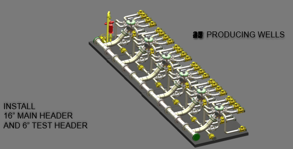
Pipeline engineers must have heard the term “flowlines” frequently. In the oil and gas industry, Flowlines transport fluids between a wellhead and a gathering station like RMS or MSV or treatment facility and vice versa. In a larger well field, multiple flowlines connect individual wells to a manifold. The flow from the manifold is then transferred by a gathering line to a pre-processing stage or to a transportation facility or vessel. Flowlines can run over land or subsea well-field. Flowlines may be buried or at grade on the surface of land or seafloor. The pipelines that collect the flow from multiple flowlines are known as gathering lines.
Flowlines are to a specific well and hence they are located at the well site. It may be a metallic or nonmetallic pipe or a hose. Most flowlines are usually very short. However, they can run for kilometers in onshore applications. Once the flowlines have brought the fluid to manifold or other pieces of process equipment, gathering lines are used. Flowlines are constructed onshore and may be lowered to the seafloor, and have terminal connectors that make an installation at the wellhead easier.
Considerations for Flowline Design
In general, the following guidelines are followed for flowline design:
1. Temperature and Pressure of Flowlines:
The operating temperature for flowlines is usually less. However, the design pressure is very high. The design pressure can range up to 238 bar. The design temperature of flowlines is normally decided based on the environmental conditions as usually process temperature is low (In the range of 60 Deg C).
The design pressure selected must be more than the maximum pressure that can be produced at any instant of the full flowline life cycle.
2. Flowline Design Code:
The normal design code followed for flow lines is ASME B31.4 or ASME B31.8. Click here to find the differences between ASME B31.4 and ASME B31.8.
3. Mechanical Strength:
Depending on the process requirement, flowline sizes vary. The wall thickness of these flowlines is determined using the Barlow formula with a design factor of 0.72. at all locations including road crossings. The Barlow formula assumes a metallic pipe. Carbon steel flowlines are typically installed above ground and this imposes additional bending and thermal (expansion) stresses not taken into account by the Barlow formula. To ensure that code allowable stresses are not exceeded due to these additional stresses on flowlines, support span, expansion loop size & spacing between limit stops, etc should be designed and checked by pipeline stress engineers.
4. Flowline Routing:
For laying new flowlines, designated flowline corridors or streets are followed to minimize land use. For these purposes, flowline town maps showing clearly designated flowline routes are developed for each field, and flowlines are planned to follow these routes only. Opportunities for inspectable bulk lines and headers should always be explored.
In planning flowline routes, inspection/maintenance access must be considered. Flowline crossovers wherever required should be provided. The number of road crossings shall be minimized. Space must be maintained for future flowlines. usually, a minimum clearance of 250 mm is required between adjacent flowlines to allow inspection by an external MFL tool. A marker plate to identify the flowline shall be provided every 200 m and at the crossings (before and after the crossing). Welding is not permitted on the coated flowlines.
For GRP or Composite pipe flowlines, the following requirements should be considered:
- Route Survey
- Topographical data
- Proximity to occupied buildings.
- Location and classes of Wadis, sand dunes, road crossings, types and density of traffic, etc as applicable.
- Environmental impact.
- The manufacturer recommended a bend radius.
- Flowline length optimization.
5. Flow-line Materials:
In general, a standard line pipe (API 5L) is used as metallic flowline material. The usual grades that contribute to metallic flowline materials are API 5L Grade B. grade X42, X52, and grade X60.
6. Flowline Expansion loops:
Expansion or contraction will occur when the temperature of the flowline material is different from that at the time of installation, or due to pressure and end-cap effects at changes in direction. Suitable expansion loops must be considered while designing flowlines. To prevent preferential expansion in one direction, anchors should be provided to ensure that each expansion loop absorbs only the thrust for which it has been designed.
7. Flowline Hook-ups:
Hook-up refers to the piping required to tie-in the flowline to the wellhead and to production facilities. Hook-up piping is designed to ANSI B31.3.
8. Flowline Installation:
- All flowlines must be properly supported following the pipe support span to maintain less than 15 mm sagging. For flowlines carrying two-phase flow, it’s better to maintain the sagging below 3 mm. So accordingly the span shall be reduced. Support shall also be provided while crossing existing buried lines.
- Buried sections of pipelines crossing existing pipelines and other services should be arranged with a ramp or standard road crossing so that access is retained at those services. Where a flowline passes by an electricity pylon, access should be maintained by the use of a ramp or standard road crossing.
- To absorb expansion stresses at road crossings, it is recommended that carbon steel lines follow the configuration that allows thermal (expansion) stresses to be channeled into the loops on either side of the crossing rather than into the pipe crossing.
- Use of low radius bends at crossings (except when used in a loop configuration) is not advised as the gooseneck formed interferes with inspection and repair.
- New flowlines shall be subjected to strength and leak tightness tests after construction. Flowlines are normally hydro-tested at a pressure of 1.25 times the design pressure.
- GRP flowlines shall always be buried. Special attention should be paid to supporting and anchoring where GRP is installed on supports in on-plot locations.
9. Commissioning of Flowlines:
When the flowline has been successfully hydro-tested, hooked up at both ends, and is ready for operational duty, it is commissioned following specific commissioning procedures.
What is a Pipeline?
A system of pipes and other components used for the transportation of fluids, between plants/facilities. A pipeline extends from pig trap to pig trap (including the pig traps), or, if no pig trap is fitted, to the first off-take isolation valve within the plant boundaries or a more inward valve if so nominated. Pipelines are designed and constructed following ASME B31.4, ASME B31.8, or ISO 14692 codes.
Difference between a Pipeline and Flowline
Both pipelines and flowlines are designed based on ASME B31.4 or B31.8 codes. However, there are some specific differences between a flowline and a pipeline.
- All flowlines are part of pipelines. However, the pipelines that run in between a wellhead and RMS or MSV, or treatment facility are termed flowlines.
- In a complete pipeline system, pipe flowlines cover a small part of the pipeline system. Hence, the flow line is a special pipeline with its length limited to the oil field area. On the other hand, pipelines run for kilometers and sometimes cross different countries.
- Flowlines carry unprocessed crude oil whereas pipelines carry partially processed or fully processed fluids.
What is a Subsea Flowline?
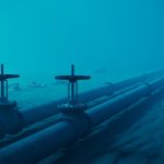
Pipelines that carry fluids in between a subsea wellhead and a surface facility or manifold are called subsea flowlines. They consist of rigid or flexible pipes and in general, carry untreated oil and gas mixtures.
Online Video Courses related to Pipeline Engineering
If you wish to explore more about pipeline engineering, you can opt for the following video courses

Dear Anup Kumar Dey,
My name is Ana Caroline, I’m a graduate student in offshore systems of the Alberto Luiz Coimbra Institute of Graduate Studies and Engineering Research, Federal University of Rio de Janeiro (COPPE/UFRJ) in Brazil. And I’m starting my monograph on Flowlines (specific theme undefined so far). I will lecture on the installation of these tubes and I wonder if you could add me with some teaching material. I found your blog quite interesting, and I used it as study, but maybe I need a little more indepth teaching material. Could you help me in any way?
I appreciate the attention. I await a return.