
A tie-in in piping refers to the process of connecting new piping to existing piping. This can be done to extend the existing piping system, add branches to it, or connect it to other equipment. Whenever there is a need for plant expansion or operation changes in an existing plant, Piping tie-ins are unavoidable. Tie-ins can be performed in a variety of ways depending on the type of piping and the conditions in which it is located. They often require careful planning and execution to ensure that they are done safely and effectively.
The philosophy behind piping tie-in is to connect new piping to existing piping to ensure that the new piping is properly connected and that the existing piping is not compromised in any way. The goal is to create a seamless integration between the new and existing piping so that the entire system functions as a cohesive unit. Additionally, the tie-in should be done in a way that is easy to maintain and repair, and that minimizes the risk of leaks or other problems. Overall, the philosophy behind piping tie-in is to ensure that the new and existing piping work together seamlessly to support the overall function and operation of the system.
The tie-in points are usually closed with Blind flanges, since removing a blind flange while operating is not convenient a shut-off valve upstream of the blind flange is installed to provide safe isolation and expansion. Tie-in Points are generally shown in P&ID and Piping Isometrics. A designated number will be allocated to Tie-in Points for example TP-034, and TP-001 as per the requirement.
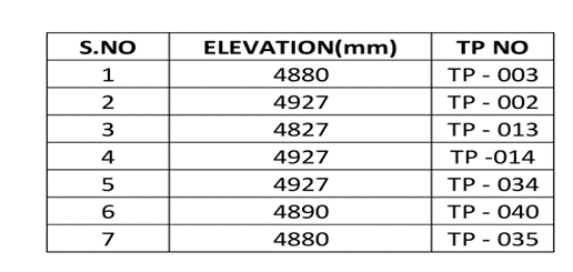
A Tie-in table must be maintained in overall General Arrangement drawings and P&ID for a better understanding of the plant interface. A Tie-In list usually consists of the Tie-in point number and elevation of the Tie-in point from the design point of view. The tie-in list can be used to estimate the cost of construction and for scheduling work well in advance of the actual piping design activity. Below is an example of a Tie-in point list table
Types of Piping Tie-ins
There are different types of Tie-in Points
- Plant Tie-In Points.
- Skid Tie-In Points.
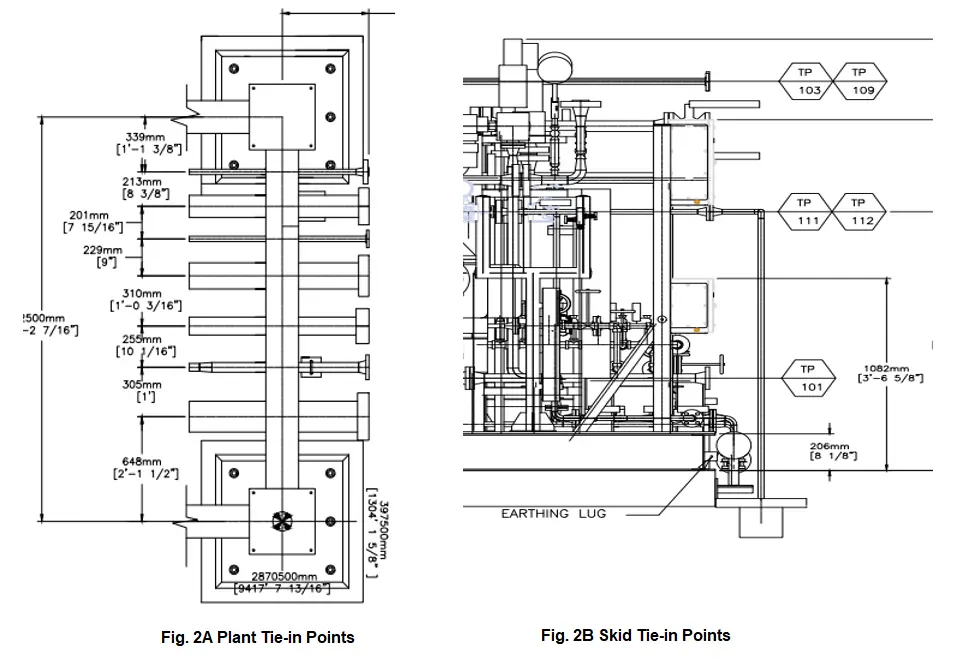
Plant Tie-In points are used for plant interface between existing plant lines or other process lines coming from a neighboring plant. The elevations should be matched with the existing plant design.
The Tie-in point flanges or isolated valves should be installed in such a way that proper spacing is maintained for operation and maintenance purposes. Please refer to Fig. 2A for plant tie-in points placed on the pipe rack.
Skid Tie-In points are located inside the plant to establish interconnecting connection piping between different skids and Equipment present in the plant. The Tie-in points are installed in such a way that it allows the process lines from other skids to be connected at a single point to ease operation and maintenance. Please refer to Fig. 2B for Skid Tie-in Points.
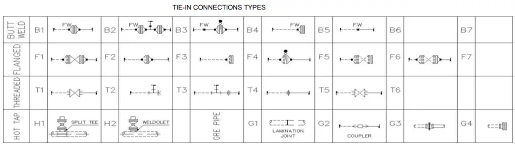
Again depending on the actual connection methodology, there are four types of pipe tie-in connections as mentioned below:
- Buttwelded Piping Tie-in
- Flanged Piping Tie-in
- Threaded Piping Tie-in, and
- Hot-tapped Tie-in connection
Refer to Fig. 3 below which clearly shows various types of tie-in connections used in the piping industry.
Piping Tie-in Point Design Considerations
When designing and installing tie-in piping, it’s often driven by the need to handle increased flow rates in utilities or processes, which might require new equipment. Once you know the process needs and have sized the tie-in piping, the next step is to think about how to isolate the piping during installation.
Shutting down the entire plant isn’t always practical, so a brief, scheduled outage might be planned to break the line and install the tie-in. Afterward, you can install the piping while the plant operates normally. To avoid multiple shutdowns, consider adding a shutoff valve upstream of the tie-in point. This allows you to safely isolate the area and install the piping later without disrupting operations.
When choosing a valve, make sure it can handle pressure on one side while being unpressurized on the other, and that it meets safety requirements like being lockable and compliant with OSHA standards. Including a drainable spool piece downstream of the valve is smart, as it lets you check for leaks and safely relieve pressure.
Finally, consider the routing of the connecting piping. While a straight route may seem easiest, adding flexibility with jogs, loops, or flexible connectors might be better for reducing stress on sensitive equipment. Tools and software are available to help analyze and optimize the piping layout, taking into account factors like pressure, temperature, and dynamic loads. The major design considerations for tie-in piping connection are
- Before considering the allocation of Tie-in points allowable Flange loading (or tie-in point displacements) should be calculated as per the standards.
- Tie-in point locations should be mentioned accurately in all directions to avoid conflict with the counter connection.
- Process engineers should decide on the Tie-in locations to avoid hazards during the operational time.
- The Engineer who decides the Tie-In locations should have a better view of maintenance and operation. A Tie-in plot plan should be prepared and checked by the plant personnel to avoid conflict.
- The valve and flange rating is considered as per the connecting line size.
- The Tie-In Items (Flanges and Valves) are considered as an additional quantity when calculating the Piping MTO.
- The Tie-in locations should be physically checked on the site before preparing the Tie-in Table.
- Change of instrumentation or control loop doesn’t need a Tie-In Point.
- Additional Drains and vents must be added as per the type and location of the Tie-ins.
- The Tie-in should be placed in a location considering the pipe support locations as pipe supports are needed based on the type of Tie-in selected.
- In the view of future equipment designers, the Tie-in fluid properties should be provided by the process engineer.
- Different kinds of shut-off valves including ball, gate, and butterfly valves are suitable for isolation.
- Based on the process fluid and pressure conditions process engineer will select the suitable valve.
- A separate GA drawing must be prepared like a plot plan which shows all the Tie-in locations in the plant.
- In some conditions, when there will be no possibility to isolate the Tie-in point or to shut down the plant process, an alternative method known as Hot Tapping can be considered to accommodate the line break. More details about hot tapping on operating lines are covered here.
Benefits of Piping Tie-in Connections
A Tie-In point in a piping/pipeline is a point where the pipeline is closed for further expansion or for connection with an existing pipeline. Tie-in points are usually located at the end of plant battery limits either on the pipe rack or sleeper or at the individual Equipment ends. This Tie-in is made along with the P&ID preparation considering the future need for the project
There are several benefits to using piping tie-ins in a piping system, these include:
- Cost-effective: Tie-ins can be a cost-effective way to add or extend a piping system, as it eliminates the need for new construction and minimizes the need for new equipment.
- Increased system efficiency: By connecting new piping to existing piping, the entire system can function more efficiently and effectively.
- Minimizes downtime: Tie-ins can be done in a way that minimizes downtime and interruption to the operation of the system.
- Improved safety: Tie-ins can be done in a way that improves safety by reducing the risk of leaks or other problems.
- Flexibility: Tie-ins provide flexibility by allowing for easy addition or modification of the piping system.
- Better maintenance: By connecting new piping to existing piping, the entire system can be easier to maintain, as any issues or problems can be identified and addressed more quickly.
- Better integration: Tie-ins create a seamless integration between new and existing piping, improving the overall function and operation of the system.
It’s important to note that, despite the benefits, proper planning and execution of the tie-in is crucial to ensure safety, quality, and efficiency. The use of a detailed method statement, following proper procedures, and having a well-trained team is key to a successful tie-in.
Piping Tie-in Schedule
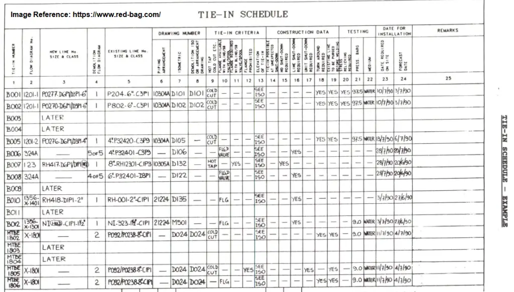
A piping tie-in schedule is a document (engineering deliverable usually prepared by process engineers) that outlines the plan and schedule for a piping tie-in project. It typically includes a detailed list of the tasks that need to be completed, the resources (e.g. personnel, equipment, materials) required to complete each task, and the timeline for each task. The schedule should also include milestones and deadlines, as well as contingencies in case of delays or unexpected issues.
The schedule should also include safety and quality assurance plans, as well as inspection and testing requirements. The piping tie-in schedule can be used as a guide for the project team and stakeholders to track the progress of the project, identify any potential issues, and make adjustments as needed. It is also used as a tool to coordinate the different activities and ensure that all are done properly and on time. A typical Tie-in Schedule is shown in Fig. 4 below:
Safety Features for Pipe Tie-in Connection
- The tie-in schedule must mention the type of work (hot work or cold work) to be used during the actual tie-in operation.
- The tie-in schedule should inform if the shutdown is required for the operation to perform.
- The lines to be demolished must be positively isolated, purged, and free from any hydrocarbon prior to cutting/unbolting.
- The tie-in schedule must be read in conjunction with the tie-in shutdown philosophy for proper planning.
- The requirement of 100% radiography for golden joints must be specifically stated.
- The construction team must ensure that the existing line is isolated, depressurized, and free from hydrocarbon prior to unbolting.
- Ensure that isolation valves are properly closed.
Piping Tie-in Procedure
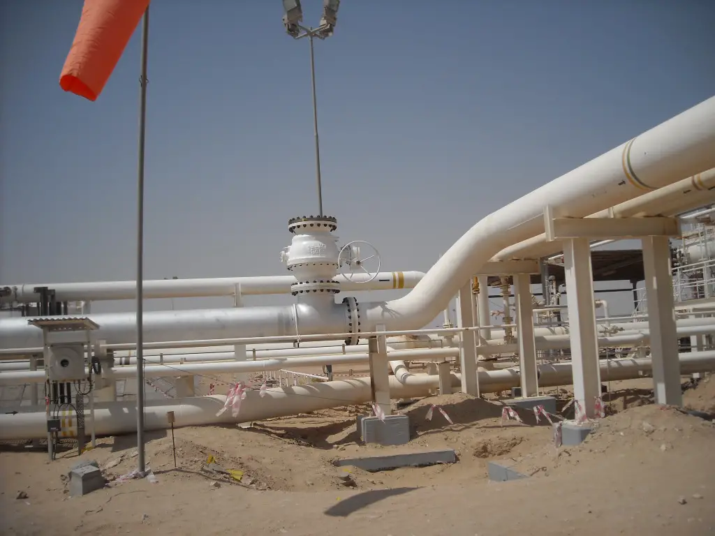
A piping tie-in procedure is a set of instructions outlining the steps that need to be taken in order to safely and effectively connect new piping to existing piping. It typically includes a detailed description of the equipment and materials that will be used, as well as the specific techniques and methods that will be employed. The procedure should also include safety precautions that need to be taken, as well as any inspection and testing requirements. Refer to Fig. 5 which shows a piping tie-in in the operating plant.
The procedure will depend on the type of tie-in and the conditions of the existing piping, but it generally includes the following steps:
- Planning: This includes identifying the scope of work, gathering all necessary information and drawings of existing piping, and determining the resources required to complete the tie-in.
- Preparation: This includes cleaning and prepping the existing piping and the new piping, as well as installing any necessary supports or hangers.
- Tying-in: This is the actual process of connecting the new piping to the existing piping, which may include cutting, welding, brazing, or flanging, among others.
- Testing and Inspection: After the tie-in is completed, the system should be tested and inspected to ensure that it is functioning properly and that there are no leaks or other issues.
- Post-tie-in: This includes cleaning up the work area, restoring the site and the equipment, and updating any records or drawings.
It’s important to note that, before starting the tie-in procedure, a permit to work should be issued and safety measures should be in place. A risk assessment should also be done to identify and mitigate any potential hazards.
Construction and Installation of Piping Tie-in/ Tie-in Schedule
Before starting construction on a line break, it’s essential to issue a line break permit. This permit covers important details like the exact location of the break, the design documents needed, the type of fluid in the line, required safety equipment, potential hazards, any special cleaning or flushing needed, valve locking and tagging instructions, and a list of all involved personnel.
If the tie-in point can be isolated, you can install the connecting piping without shutting down the process. However, if isolation isn’t possible and the line can’t be shut down, a procedure called “hot tapping” is necessary. Hot tapping allows you to connect to a live, pressurized line, often used for steam, gas, water, or other utilities that must keep flowing.
The basic steps for hot tapping include welding a fitting onto the line, installing and testing a gate valve, attaching the hot tap machine, boring into the line, and then safely removing the machine after closing and locking the valve. This is a specialized task that should be done by experienced companies. After hot tapping, you can proceed with installing the connecting piping, followed by pressure and leak testing before the new piping is put into service.
The installation of piping tie-in/tie-in schedule is a multi-activity task performed as follows:
Tie-in Preliminary works
- Notification from Company
- Pre-fabrication of Tie-in spool
- NDE & Hydrotest for Tie-in spool
- Ultrasonic Testing for existing Tie-in line
- Excavation and installation of foundation (if required)
- Scaffolding, Structure, Platform, Support installation
Tie-in Execution Works
- Positive Isolation from Company
- Blinding (Gas free line)
- Cold cutting and Installation of tie-in spool
- Welding, NDT, Hydrotest
- Line Blowing and Drying
- De-blinding and client handover
Touch-up and painting
- Scaffolding removal and housekeeping
- Handover to operation team/company
Piping Tie-in Method Statement
A method statement for piping tie-in is a document that outlines the specific procedures and steps that will be taken to safely and effectively connect new piping to existing piping. It is a detailed plan of the work that will be done, including the equipment and materials that will be used, the techniques and methods that will be employed, and the safety precautions that will be taken.
A typical method statement for piping tie-in would include the following information:
- Introduction: A brief overview of the scope of work and the objectives of the tie-in.
- Equipment and Materials: A list of the equipment and materials that will be used, including any special tools or safety equipment.
- Procedures: A step-by-step description of the procedures that will be followed, including the techniques and methods that will be used to connect the new piping to the existing piping.
- Safety: A description of the safety precautions that will be taken, including any specific hazards associated with the tie-in and the measures that will be taken to mitigate those hazards.
- Inspection and Testing: A description of the inspection and testing that will be done after the tie-in is completed, including any acceptance criteria that must be met.
- Quality Assurance: A description of the quality assurance procedures that will be followed, including any inspections or tests that will be done to ensure that the work is done to the required standards.
- Emergency Procedures: A description of the emergency procedures that will be in place in case of any accidents or incidents.
It’s important to note that, before starting the tie-in, the method statement should be reviewed and approved by relevant parties, such as the safety officer, the quality manager, and the project manager.
Hi Mr. Karthik Pindiprolu,
Your explanation (summary) about TIE-IN is really excellent for the new ones in this field.
Congrats and thank you for sharing.
*I’ve executed 600+ tie-ins and performed (designed) 1.100+
Hello sir,
I need tie-in drawings with MTO. I have some doubts about P&ID drawings related to tie-in quantity take-off. Could you share them with me? If I can refer to tie-in drawings with quantities, I will be able to understand easily.
I appreciate the effort you made to explain the following topic in easy and efficient way.
Keep working and share the knowledge.
you are doing a great work
Excellent, detailed and precise. Congratulations for the excellent work and for sharing. I suggest to include at top or bottom the date of last update.
Really nice explain.
Last 30/12/24 we completed 7 tie-in in this month and follow all these steps as per Qatar energy LNG procedure.
You explain the actual workflow to execute these job.
But actually it’s very critical and change job.
Can we make a Tie-In from the bottom of existing pipe?