In this brief write-up, I discuss Tresca and Von Mises theories of failure and discuss their applicability in piping and pressure vessel applications. The article begins with briefly describing the theoretical background behind Tresca and Von Mises.
1. Tresca and Von Mises Explained
1.1 Hydrostatic and Deviatoric stresses and invariants
1.1.1 Principal stresses and invariants of the stress tensor
The stress vector 𝑇𝑛 on the plane with unit normal n is generally not in the direction of unit normal n. If however, the orientation of a plane is such that indeed is the case, then on that plane there is only normal stress and no shear stress. Such planes are known as principal planes, and it can be proved mathematically that at every point of a body, there exist three mutually perpendicular principal planes.

If 𝜎1,𝜎2,𝜎3 symbolize the principal stress, then Ref ( ) shows that the solution of the principal stress problem is an eigenvalue problem and results in a solution of a cubic equation:
(𝑻𝒏)=𝝈(𝒏) Equation 1-The Eigenvalue problem
Where (𝑇𝑛) is the traction vector, 𝑛 is the normal to the plane where (𝑇𝑛) acts, 𝜎 is a scalar.
σ3 – I1 σ2 + I2 σ – I3 = 0 Equation 2 -Cubic equation to solve for principal stresses
Where I1 = sum of the diagonal terms of σij
I2 = sum of the cofactors of the diagonal terms of σij
I3 = determinant of σij
The three “I”s are the invariants of the stress tensor, i.e. their values do not change irrespective of the rotation of the coordinate axes.
Stress tensor is usually decomposed into two parts: hydrostatic, which is responsible for “volumetric change” and “deviatoric” which is responsible for “shape change”.
The hydrostatic component of the stress tensor is defined as =(1/3) I1 and symbolized as “𝑝” and the deviatoric stress tensor is defined as:
sij = σij –pδij Equation 3
Here, δij = Kronecker Delta

Since subtracting a constant normal stress in all directions does not change the principal directions, so the principal directions for the stress deviator are the same as the principal directions for the stress tensor. In terms of principal stresses, the stress deviatoric tensor is:

To obtain the invariants of the deviatoric stress tensor, we see that a cubic equation similar to Equation 2 will follow and can be written as:
s3 – J1 s2 + J2 S – J3 = 0 Equation 6
The three “J”s are the invariants of the deviatoric stress tensor i.e. their values do not change irrespective of the rotation of the coordinate axes.
It can be shown [1] that the invariants J1, J2, and J3 are related to the stress invariants of the stress tensor by the following relationship:

It can be proved mathematically that the necessary and sufficient condition for a state of stress σij to be a pure shear state is that σii =0 i.e. the first invariant is zero. Therefore, the stress deviator tensor sij is a state of pure shear.
1.2 Octahedral stress
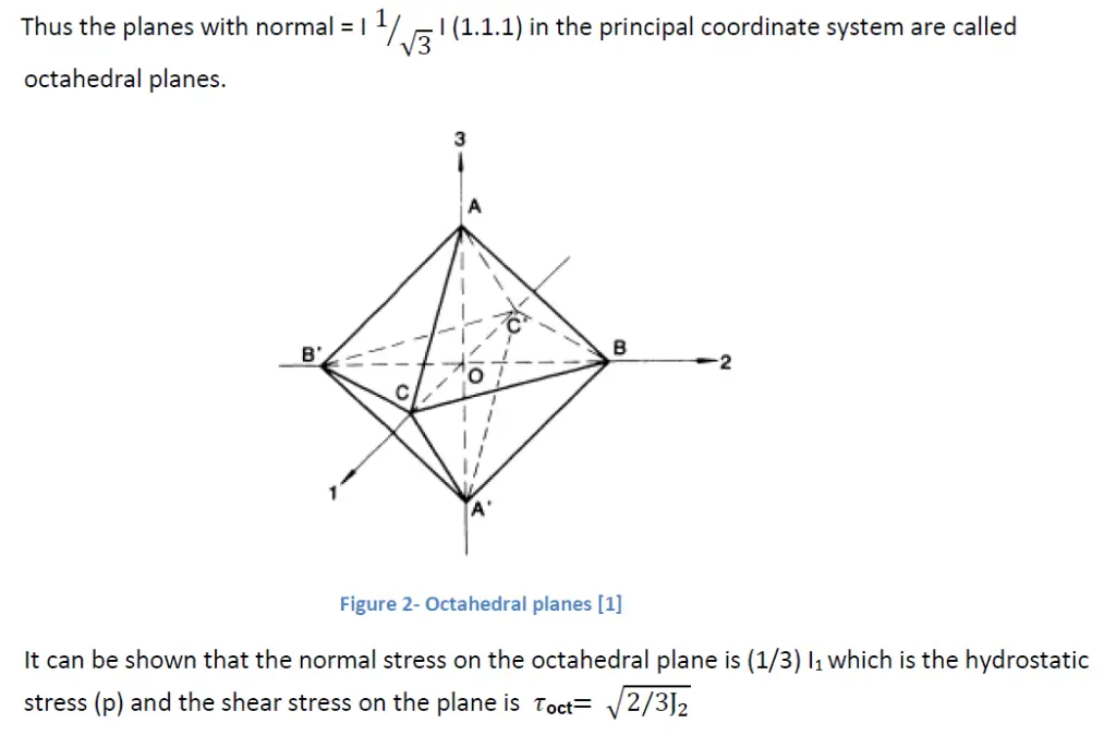
The octahedral plane is a plane whose normal makes equal angles with each of the principal axes of stress.

1.3 Haigh-Westergaard stress space
In a coordinate system made up of “principal axes, hydrostatic stress is represented by a vector that is oriented equally with the three axes, and any plane perpendicular to this axis is a plane of pure Deviatoric stresses and referred to as the deviatoric plane.

A projection of the principal axes coordinate system on the deviatoric plane looks as

2. Tresca and Von Mises
2.1 Tresca
As per the Tresca theory, Yielding would occur at a point when the maximum shear stress reaches a critical value.

2.2 Von-Mises
As per the Von-Mises theory, Yielding takes place when Octahedral shear stress takes a critical value


3. Comparison between Tresca and Von Mises
A comparison between Tresca and Von Mises was done experimentally by Lode, Taylor, and Quincy. To evaluate the results, the Lode parameter which was introduced is defined as

Where 𝜎1>𝜎2>𝜎3
If we consider the following cases

Solving 𝜎2 from Equation 15 to Equation 14 and using 𝜎𝑒=𝜎𝑦𝑠 results in

Comparison of the equations 19 and 20 with experimental results are shown as below
![Figure 6 [2]](https://whatispiping.com/wp-content/uploads/2024/11/image-15.png)
Taylor and Quincy conducted combined torsion and tension tests on thin-walled tubes made of steel, copper, and aluminum. Axial stress is designated as 𝜎𝑥 and Shear stress as 𝜏𝑥𝑦
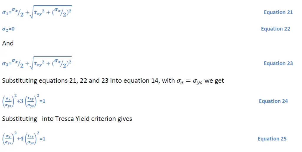
For plane stress situations expressing the results in terms of principal stress, we have

Equations 24 and 25 are shown along with experimental results as
![Figure 7 [3]](https://whatispiping.com/wp-content/uploads/2024/11/image-17.png)
As with the Lode test results, Von Mises yield criteria show a better correlation with experimental results.
References
- Plasticity for structural engineers Chen, W.F and Han D.J , J R Ross publishing
- Lode W , “ Versuche ueber den Einfluss der mittleren Hauptspannung auf das FLiessen der metalle Eisen, Kupfer und Nickel”, Z.Physik,36,913,(1926)
- Taylor, G.I and Quincy, H, “ The distortion of metals”, “ Trans.Royal Society ( London), Series A, 230,323-362(1931)
