A flow meter is a device that measures the flow rate of a fluid. Flow meters are flow-measuring instruments used to measure the linear, nonlinear, mass, or volumetric flow rate of a gas or a liquid. Flow meters are also known as Flow Gauges or flow measurement instruments. Accurate flow measurements of gases and liquids are required for better control and quality of industrial processes.
This article will provide the following information in brief:
- Types of Flowmeters/ Flowmeter types
- Operating Principle of Each type of Flowmeter
- Design Features of each flowmeter.
- Advantages and Disadvantages of each type of Flowmeters
- Selection and Application of those Flowmeters
Types of Flowmeters | Flowmeter Types
Broadly two types of flow meters are widely used in industries:
- Volumetric Flowmeters and
- Mass Flowmeters
Volumetric Flowmeters
Volumetric flow meters got their name because these flow meters measure the fluid volume passing through a specific location in a set period of time. Volumetric flow meters provide an instantaneous analog, digital, or pulse output of the volumetric flow rate of the liquid or gas. Various types of Volumetric Flowmeters are available as listed below
- Differential Head type
- Orifice plates
- Venturi meters
- Annubar
- Differential Area type (Rotameters)
- Electromagnetic flowmeters
- Ultrasonic flowmeters
- Turbine flowmeters
- Vortex flowmeters
- Positive Displacement Meters
Mass Flowmeters
Mass flow meters measure the fluid mass flow rate that travels through a tube per unit of time. There are two types of mass flowmeters as mentioned below
- Coriolis Mass flowmeter and
- Thermal Mass flowmeters
Differential Head Type Flowmeters
- The difference in pressure exists between the upstream & downstream sides of a restriction in a confined fluid stream, which is related to the square of fluid velocity.
- Q α √ ▲P
Where Q = Volume flow rate and ▲P = Differential pressure between taps
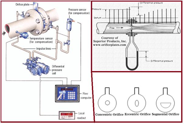
Types of Orifice plates (Fig. 1)
- Concentric orifice plate: Most commonly used
- Segmental & Eccentric orifice plate: Used for fluids containing suspended solids.
Tappings for the Orifice plates:
- Corner taps (< 1 inch)
- D and D/2 taps ( 2 to 16 inches)
- Flange taps (> 16 inches)
Features of Orifice Plates
- Design Pressure: No limitation. Limited by DP transmitter
- Design Temperature: No limitation. Limited by DP transmitter
- Sizes: Maximum size is the pipe size
- Flow range: limited only by pipe size.
- Fluids/ Applications: Cryogenic/clean gases & liquids/ Steam (saturated/superheated)
- MOC: No limitation (Steel/ Monel/nickel/ haste alloy)
- Accuracy: It varies from ±0.25% to ±0. 5% of actual flow. The accuracy of the DP transmitter varies from ±0.1% to ±0. 3% of full-scale error.
- Rangeability is 3:1 to 5:1.
- Upstream length/ Downstream straight length is 20 / 5
Advantages of Orifice Plates
- Easily installed between flanges.
- Fabrication is simple and inexpensive.
- No limitations on the materials of construction, line size, and flow rate
- Cost is relatively independent of pipe diameter since the cost of DPT is fixed.
- No process interruption for the exchange of the DP transmitter.
Disadvantages of Orifice Plates
- High permanent pressure loss & hence high energy consumption to overcome pressure loss.
- Impractical for systems with low static pressure.
- Measuring ranges from about 3:1 to 5:1.
- Accuracies decrease with Beta ratios above approximately 0.7.
- Subject to damage by water hammer and foreign objects.
Venturi Meters
A venturi tube (Fig. 2) measures flow rates by constricting fluids and measuring a differential pressure drop. In the upstream cone of the Venturi meter, velocity is increased, and the pressure is decreased. Pressure drop in the upstream cone is utilized to measure the rate of flow through the instrument. Further details of the venturi meter are provided here
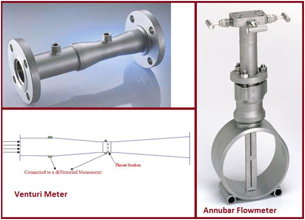
Features of Venturimeters
- Design Pressure: No limitation. Limited by DP transmitter/ pipe pressure ratings.
- Design Temperature: No limitation. Limited by DP transmitter/ pipe pressure ratings
- Sizes: 25 mm to 3000 mm
- Fluids/ Applications: Clean Liquids/ clean gases
- Limited applications: Dirty /corrosive/viscous Liquids & Dirty gases
- Flow range: limited only by pipe size and beta ratio.
- MOC: No limitation (cast iron/ carbon steel/ SS/Monel, Titanium, Teflon, Hastelloy, Naval Bronze/haste alloy)
- Accuracy: It varies from ±0.25% to ±0. 75% of actual flow. The accuracy of the DP transmitter varies from ±0.1% to ±0. 3% of full-scale error.
- Rangeability is 3:1 to 5:1.
- Upstream length/ Downstream straight length is 20 / 5
Advantages of Venturimeters
- Lower head losses than orifice plates reducing the capital expenditure on pumping eqpt. / save pump energy costs
- No process interruption for the exchange of the DP transmitter.
- Can be used for temperature extremes
- Cryogenics or High Temperatures
Disadvantages of Venturimeters
- Highly expensive
- Larger and heavier to handle.
Annubar Flowmeter
The Annubar flowmeter is a device to measure the fluid flow (liquid, vapor, or gas) in a pipeline. The flow is measured by creating a differential pressure. As per Bernoulli’s theorem, this differential pressure is proportional to the square of the fluid velocity in the pipeline. The annubar flowmeter measures this differential pressure which is then converted to flow rate using a secondary device.
- The probe is installed in the median line as a pressure sensor.
- With the flow, the probe records both the static and the dynamic pressure via the probe openings.
- In the minus chamber of the annubar, lying on the opposite side, only the static pressure has any effect
- The differential pressure corresponds to the dynamic pressure in the pipeline & the flow can is calculated directly.
Features of Annubar Flowmeters
- Design Pressure: Upto 97 bars (38 Deg. C) / 55 bars (370 Deg. C)
- Design Temperature: Upto 400 deg.C
- Sizes: 50 mm to 3000 mm
- Fluids: Clean Liquids, gases, and steam
- MOC: Brass/steel/ stainless steel/ Hastelloy
- Accuracy: It varies from ±1% to ±2% of actual flow. The accuracy of the DP transmitter varies from ±0.1% to ±0. 3% of full-scale error.
- Rangeability is 3:1 to 5:1.
- Upstream length/ Downstream straight length is 20 / 5
Advantages of Annubar flowmeters
- The integral manifold head allows direct mounting of DP transmitters
- Hot tapping: Insertion/ installation without system shutdown
- Very low-pressure drop
Disadvantages of Annubar flow meters.
- Not suitable for viscous and slurry applications
- Can be used only for clean fluids.
Variable Area Flowmeters/ Rotameters
Variable area flowmeters or rotameters are one of the widely used common flowmeter types. It consists of a vertical glass or plastic tube. The size of the tube varies from top to bottom; because of this, it got its name as a variable area flowmeter. Inside the tube, there is a free-moving metering float.
- A free-moving float is balanced inside a vertical tapered tube
- As the fluid flows upward the float remains steady when the dynamic forces acting on it are zero.
- The flow rate is indicated by the position of the float relative to a calibrated scale.
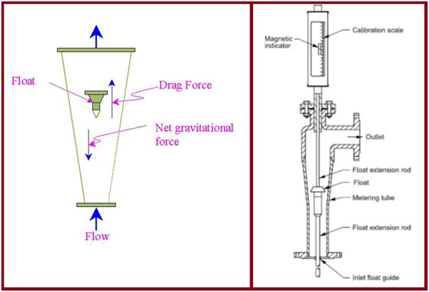
Design Features of Rotameters
- Design Pressure: Upto 350 PSIG (GLASS TUBE) / 720 PSIG (METAL TUBE).
- Design Temperature: Upto 400 deg.C (GLASS TUBE) / 538 Deg. C (METAL TUBE).
- Sizes: up to 75 mm
- Fluids/ Applications: Clean liquids, gases, and vapors
- Flow range: upto 920 cubic m/hr for liquids & 2210 cub.m/hr for gases
- MOC: Borosilicate glass/brass/steel/ stainless steel/ Hastelloy
- Accuracy: It varies from ±1% to ±2% of actual flow.
- Rangeability is 10:1
- Upstream length/ Downstream straight length is 10 / 5
Advantages of Rotameters
- Simple, robust, and linear output
- It does not require external impulse or lead lines.
- The pressure drop is minimal and fairly constant.
Disadvantages of Rotameters
- Vertical installation only.
- Glass tubes limit pressure & temperature and are subject to breakage from hydraulic & thermal shock
- Glass tubes eroded by undissolved solids & unsuitable for metering alkaline solutions
- Metal tube meters are more expensive.
- Foreign particles can accumulate around the float & block the flow
Magnetic Flowmeters
- Operate on Faraday’s Law of magnetic induction.
- When a conductive fluid moves in a magnetic field, a voltage is generated between two electrodes at right angles to the fluid velocity and field orientation.
- The flow tube has a fixed area & field intensity so the developed voltage is linearly proportional to the volumetric flow rate.
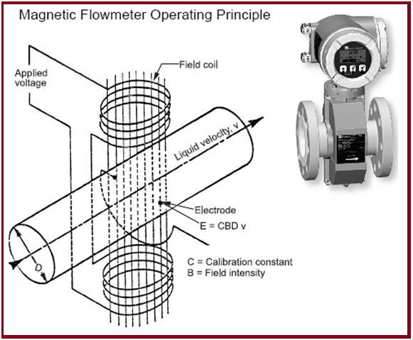
Design features of Magnetic Flowmeters
- Design Pressure: 20 BARS to 172 BARS
- Design Temperature: Upto 120 deg.C with Teflon liners / 180 Deg.C with ceramic liners
- Sizes: 2.5 mm to 3000 mm
- Fluids : Liquids (clean/ corrosive/dirty/viscous/ slurry)
- Velocity range: 0.1 to 10 m/s
- MOC: Liners: ceramic/ teflon/rubber : Electrodes: Platinum/ hastelloy/SS
- Accuracy: It varies from ±0.5% to ±1% of actual flow.
- Rangeability is 10:1
- Upstream length/ Downstream straight length is 10 / 5
Advantages of magnetic Flowmeters
- Flow rate unaffected by fluid density, consistency, viscosity, turbulence, or piping configuration.
- Highly accurate due to the absence of moving parts/ external sensing lines
- Corrosion-resistant using Teflon liner and platinum electrodes
- Wide flow measuring ranges & no pressure drop
Disadvantages of Magnetic Flowmeters
- Costly, relative to other flowmeter types.
- The temperature of the fluids being metered is limited by the liner material rating.
- Cannot be used for gas flow measurements
Vortex Flowmeters
- An obstruction is placed across the pipe bore at a right angle to fluid flow.
- As fluid flows, vortices are shed from alternating sides of the body & this shedding frequency is directly proportional to fluid velocity.
- Detection of the vortices by means of pressure changes in the vortex stream.
- The rate of creation of vortices is directly proportional to the flow rate.
Design Features of Vortex Flowmeters
- Design Pressure: 138 bars
- Design Temperature: -200 Deg. C to 400 Deg.C
- Sizes: 15 mm to 300 mm
- Fluids: Gases (clean/ dirty) and clean liquids
- Velocity range: 0.3 to 10 m/s (liquids) and 6 to 80 m/s (gases)
- MOC: mostly in stainless steel, some in plastic
- Accuracy: It varies from ±0.5% to ±1% of actual flow for liquids and ±1% to ±1.5% for gases
- Rangeability is 20: 1
- Upstream length/ Downstream straight length is 20 / 5
Advantages of Vortex Flowmeters
- Minimal maintenance, no moving parts.
- Calibration using fluid flow is not required & unaffected by viscosity, density, pressure, and temperature within operating specifications.
- Digital or analog output.
Disadvantages of Vortex Flowmeters
- At low flows, pulses are not generated and the flowmeter can read low or even zero.
- Reynolds number should be greater than 10000.
- Vibration can cause errors and inaccuracy.
- Correct installation is critical as protruding gasket or weld beads can cause vortices to form, leading to inaccuracy.
- Long, clear lengths of upstream pipework must be provided, for orifice plate flowmeters.
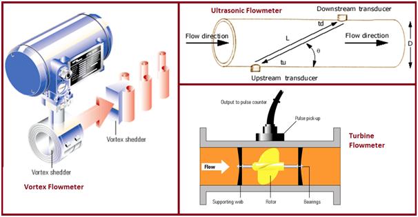
Ultrasonic Flowmeters
- A pair (or pairs) of transducers, each having its own transmitter and receiver, are placed on the pipe wall, one (set) on the upstream and the other (set) on the downstream.
- The time for acoustic waves to travel from the upstream transducer to the downstream transducer (td) is shorter than the time it requires for the same waves to travel from the downstream to the upstream (tu).
- The larger the difference, the higher the flow velocity.
Design Features of Ultrasonic Flowmeters
- Design Pressure: 207 bars (insertion type)/ unlimited (clamp on type)
- Design Temperature: -180 Deg. C to 260 Deg.C
- Sizes: 3 mm to 3000 mm
- Fluids : clean gases, clean/corrosive liquids (with little/no solids/ bubbles)
- Velocity range: 0.3 to 15 m/s
- MOC: mostly in stainless steel/ alloys
- Accuracy is: +0.5% of flowrate for insertion type/+1% to +3% of flowrate for clamp on type
- Range ability is 10: 1 to 300: 1
- Upstream length/ Downstream straight length is 10 / 5
- Bidirectional flow measurement
- For insertion type, hot tapping in pressurized pipelines is possible
Advantages of Ultrasonic Flowmeters
- No obstruction/ moving parts in the flow path
- No pressure drop
- Low maintenance cost
- Multi-path models have higher accuracy for wider ranges of Reynolds number
- Can be used in corrosive fluid flow
- Portable models available for field analysis and diagnosis
Disadvantages of Ultrasonic Flowmeters
- Only clean liquids and gases can be measured
- Higher initial setup cost
Turbine Flowmeters
- Consists of a multi-bladed rotor mounted at right angles to the flow & suspended in the fluid stream on a free-running bearing.
- The diameter of the rotor is slightly less than the inside diameter of the flow metering chamber.
- Speed of rotation of rotor proportional to the volumetric flow rate.
Features of Turbine Flowmeters
- Design Pressure: 1500 PSIG
- Design Temperature: 150 Deg. C
- Sizes: 5 mm to 600 mm (Full bore type)/ > 75 mm for insertion type
- Fluids : Clean liquids/ gases and vapours
- Velocity range: 0.3 to 15 m/s
- MOC: mostly in stainless steel/ hastelloy
- Accuracy is: +0.25% to + 0.5% of flowrate for full bore type/+1% to +3% of flowrate for insertion type
- Range ability is 10: 1
- Upstream length/ Downstream straight length is 15/ 5
- Bidirectional flow measurement
- For insertion type, hot tapping in pressurized pipelines is possible
Advantages of Turbine Flowmeter
- Very accurate. Commonly used to prove other meters.
- The digital output provides for direct totalizing, batching, or digital blending without reducing accuracy.
- There is less tendency to read high in pulsating flow than in head or variable-area type meters.
Disadvantages of Turbine Flowmeters
- Not usable in dirty streams or with corrosive materials.
- Subject to fouling by foreign materials -fibers, tars, etc.
- Bearings are subject to wear or damage. Shift in calibration if bearings replaced
- It can be damaged by overspeeding (over 150 percent) or by hydraulic shock.
- Pressure loss at rated flow varies & can be high.
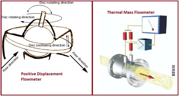
Positive Displacement Flowmeters
- This meter repeatedly entraps the fluid into a known quantity and then passes it out.
- The quantity of the fluid that has passed is based on the number of entrapments.
- The volume flow rate can be calculated from the revolution rate of the mechanical device.
Features of Positive Displacement (PD) Flowmeters
- Design Pressure: 1500 PSIG (liquids)/: 100 PSIG (gases)
- Design Temperature: 293 Deg. C (liquids)/: -34 to 60 Deg. C (gases)
- Sizes: 6 mm to 400 mm
- Fluids: Clean Liquids/ gases
- Flow range: 0 – 20000 GPM (liquids)/ : 0 – 3000 cub.m/hr (gases)
- MOC: mostly in aluminum, stainless steel, plastics, Hastelloy
- Accuracy is + 0.5% to + 1% of flowrate
- Range ability is 15:1
Advantages of PD Flowmeters
- Good accuracy and high rangeability
- Can be used in viscous liquid flow
- Low to medium initial set-up cost
- Require no power supply and is available in a wide variety of readout devices
Disadvantages of PD Flowmeters
- Maintenance is required at frequent intervals because of the `moving parts.
- High-pressure drop due to obstruction
- Not suitable for low flow rate
- Not suitable for fluids with suspended solids
- Gas (bubbles) in liquid could significantly decrease the accuracy
Thermal Mass Flowmeter
- Operates by monitoring the cooling effect of a gas stream as it passes over a heated transducer.
- Gas flow passes over two PT100 RTD transducers.
- The temperature transducer monitors the actual gas process temperature, whilst the self-heated transducer is maintained at a constant differential temperature by varying the current through it.
- The greater the mass flow passing over the heated transducer, the greater the current required to keep a constant differential temperature.
- The measured heater current is, therefore, a measure of the gas mass flow rate.
Design Features of Thermal Mass Flowmeters
- Design Pressure: 1200 PSIG
- Design Temperature: 176 Deg. C
- Sizes: 15 mm to 1000 mm
- Fluids: Clean gases
- Flow range: 0 – 2500 SCFM
- MOC: mostly in stainless steel/ glass, Teflon, monel
- Accuracy is +1% to + 2% of flowrate
- Range ability is 10: 1 to 100:1
- Upstream length/ Downstream straight length is 5/ 3
Advantages Of Thermal Mass Flowmeter
- No temperature or pressure compensation required
- Linear output (as temperature differential is proportional to mass flow)
- Can be used on corrosive process streams if proper materials are specified
- DC voltage or 4 to 20 mA dc outputs are available
Disadvantages of Thermal Mass Flowmeters
- Practical for gas flow only
- Subject to blockage by foreign particles or precipitated deposits due to small openings in the flowmeter
- Power requirements are excessive in larger pipe sizes
- Has to be taken out of the process line for servicing
- Accurate field calibration is difficult
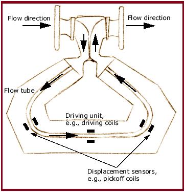
Coriolis Mass Flowmeter
- When a moving mass is subjected to an oscillation perpendicular to its direction of movement, Coriolis forces occur depending on the mass flow.
- When the tube is moving upward during the first half of a cycle, the fluid flowing into the meter resists being forced up by pushing down on the tube.
- On the opposite side, the liquid flowing out of the meter resists having its vertical motion decreased by pushing up on the tube. This action causes the tube to twist.
- This twisting movement is sensed by a pick-up and is directly related to the mass flow rate
Coriolis Mass Flowmeter Characteristics
- Design Pressure: 345 bar
- Design Temperature: 200 to 426 Deg. C
- Sizes: 1.5 mm to 150 mm
- Fluids/ Applications: Liquids (clean/ dirty/viscous/ slurries) clean /liquified gases
- Flow range: 0 – 25000 lb/m
- MOC: mostly in stainless steel, Hastelloy/titanium
- Accuracy is + 0.15% to + 0.5% of flowrate
- Range ability is 20: 1
- Bidirectional flow measurement
Advantages of Coriolis Mass Flowmeters
- Capable of measuring difficult handling fluids
- Independent of density changes, flow profile and flow turbulence. Hence straight lengths are not required.
- No routine maintenance is required since no moving parts
- High accuracy
Disadvantages of Coriolis Mass Flowmeters
- Not available for large pipes (up to 150 mm only)
- High flow velocities are required for detection resulting in a high-pressure drop
- Expensive compared to other flowmeters
- Difficulty in measuring low-pressure gases.
Application of Flowmeters / Selection of Flowmeters
Clean liquids/gases
- Orifices
- Venturi
- Annubar
- Variable Area
- Magnetic (only liquids)
- Ultrasonic
- Vortex
- Coriolis Mass Flowmeters
- Thermal mass flowmeter (only gases)
- PD meters
Dirty Liquids
- Most suited: Magnetic/Coriolis Mass Flowmeters
- Limited applications: Venturi meters
Dirty Gases
- Most suited: Vortex meters
- Limited applications: Venturi meters/Thermal mass flowmeter/Variable area flowmeter
CORROSIVE LIQUIDS: Magneticflowmeters/Ultrasonic flowmeters
NON-NEWTONIAN LIQUIDS: Coriolis Mass Flowmeters
VISCUOUS LIQUIDS: Coriolis/Magnetic/Positive Displacement Meters
ABRASIVE SLURRIES: Magnetic flowmeters/Coriolis Mass Flowmeters
FIBROUS SLURRIES: Magnetic flowmeters/Coriolis Mass Flowmeters (limited applications)
Saturated Steam
- Most suited: Orifice DP meters/ Vortex flowmeters
- Limited applications: Venturi meters/Variable area meters
Super-heated Steam
- Most suited: Orifice DP meters
- Limited applications: Venturi meters
Cryogenic Applications: Venturi-meters/Orifice plates
Parameters affecting Flowmeter Selection
There are various factors that influence the flowmeter selection for a specific industrial process. Some of those factors are:
- The fluid phase and characteristics; for example, gas, liquid, steam
- Flow conditions and flow range; for example clean, dirty, abrasive, or viscous fluid.
- Process design parameters; for example, pressure, temperature ranges, density, viscosity, etc.
- Pipe size, material, flange pressure rating, etc.
- Accuracy desired.
- Material of Construction (corrosive or non-corrosive fluid).
- Maximum and Minimum measurement range and turn-down rates.
- Repeatability and cost-effectiveness.
- Environmental considerations, if any.
- Regulatory and certification requirements.
- Location of the flowmeter in the piping system.
- Measurement in mass or volumetric unit.
Installation of Flowmeters
Flow measurement using flowmeters is an essential activity for any industry. So, it must provide reliable and accurate data. The accuracy and repeatability of measured data, to a large extent, depend on the correct installation of the flowmeter. Some of the critical steps that must be followed during flowmeter installation are listed below:
- It must be installed in the proper location.
- It should not be installed where there are vibrations or magnetic fields.
- The flow direction must be known before installation.
- Flowmeters should be installed on a straight pipe.
- Some flowmeters may need straight lengths upstream and downstream of the flowmeter. It should be maintained for accurate results.
- For liquid flow applications, the downward flow should be avoided.
- Ensure that the flowmeter is completely filled with fluid.
- Vapor or air in liquid lines and liquid droplets in gas lines should be avoided.
- It’s preferable to install a filter upstream of the flowmeter to remove solids.
- If repair is required, a bypass line should be provided.

Hi Anup Kumar,
I would like to know the standard method of installation of Differential Pressure Transmitter in hot water pipe lines of 8″ dia.
I want to install DPT but need to know the exact or recommended distance to be maintained to connect the 1/2″ tubing in the pipeline as side mounting and whats the best practice for any pressure transmitter and DPT and FIT.
Please provide your kind feedback.
Mohamed
hhahahaha
Dear Sir,
Kindly what mean “Measuring range to about 3:1 to 5:1.” in orifice flow meter
Greetings
MGMK
The orifice plate accuracy seems very high. Other sources I have read are saying 2-5%.
Sir I want piping supervisor interview
How to qualify interview
i need a flowmeter which can be used for fluis with soild particles .please suggest me one.
Informative information on flow meters in this article. You can provide all information on the flow meter. But how to measure liquid in the open channels using flow meters?
Request for recommendation:
Need a flow meter and pressure gauze for residential water line and for high pressure landscape irrigation.
Would you please recommend the most economical and efficient products.
Thanks.
Very Informative
Sir upstream and down stream 20/5 how to measure,
Hi,
this is really a nice document and helpful for the students to understand the working of flowmeters in details…
We like your blog and we also provide the same type of services like air flow meter and air gas flow meter.
Which company manufactures the best quality Insertion Thermal Mass Flow Meter in India ?
Very well-articulated document!!