
The orifice flow meter is a device widely used for flow measurement applications in the Oil & gas industry. The orifice flow meter is capable to measure the flow rate of both services (Liquid & Gas) and steam service. An orifice plate is used to create the differential pressure in the process line by acting as an obstruction for flow. The flow rate passing through the orifice in the processing pipeline is directly proportional to the square root of differential pressure (Pressure Drop).
The orifice plate is fitted into line with the flanged connection in the pipe of the process line. The orifice bore diameter size is smaller than the pipe diameter, thus reducing the area which means a lower flow rate is passing through the orifice construction. The location at which the orifice meter cross-sectional area is minimum and fluid tends to regain energy after this point is called the Vena contracta.
Principle of Orifice Flowmeter
The principle on which the orifice meter works is the differential principle. Flow rate is calculated when fluid (Liquid or gas) is passed through the Orifice flow meter, differential pressure is generated.
According to Bernoulli’s equation, the flow rate is directly proportional to the square of the pressure drop. The flow rate is calculated from the differential pressure indicated on the display of the orifice flow meter.
“Reduction in flow passage accelerates the fluid thus pressure difference is created. Measurement of flow rate is based on the inlet pressure and pressure reduction point to give a discharge flow rate of pipe”.
Important technical terms in Orifice Flowmeter
Some key terms are important terms for the understanding of orifice meter design and working principle.
Beta ratio (β):
The beta ratio is the ratio between the diameter of the orifice bore to the inside diameter of the pipe.
Beta (β) = Orifice Bore Diameter (d) / Internal Pipe Diameter (D)
The beta ratio has no standard range, recommended range for the beta ratio is between 0.2 – 0.7.
Case if the beta ratio is less than 0.2 (Beta ratio < 0.2):
In this case, the following observations are found:
- The diameter of the orifice bore is small.
- High-pressure drop, hence higher flow restriction.
- Increase in uncertainty and decrease in accuracy.
- Chances of cavitation and flashing take place, because higher pressure drop line pressure may go below the vapor pressure of the fluid.
Case if the beta ratio is greater than 0.7 (Beta ratio > 0.7):
In this case, following observations are found:
- The diameter of the orifice bore is larger.
- Low-Pressure drop, hence minimum the flow restriction.
- Experiences difficulty in measuring low-pressure applications service.
Reynolds Number:
Reynolds number plays an important role in the selection of the type of orifice plate. Reynolds number is the ratio of inertial forces to viscous forces.
At low Reynolds number flow geometry or profile gets disturbed, a Reynolds number greater than 10000 is recommended so that the coefficient of discharge becomes constant throughout the indicated curve below.
Selection of differential pressure transmitter range:
At full flow conditions differential pressure range between 0 to 2500 mm H2O (0 – 25 KPA or 0 – 100 inch of water) is adopted very commonly for the orifices.
Refer below-shown figure shows that the 0 – 100 Inches DP range is sufficient in which curve minimum error, due to the change in density to the change in temperature. This range of differential pressure also indicates that accuracy is maximum than the other cases.
Installation of Orifice flow meter:
Orifice-type flow is directly installed in the process line using the flanged connection. The orifice meter consists of taps for pressure measurement which are connected to a pressure measuring device situated according to the design construction.
Precautions during installation
Within a 1 or 1.5-meter distance, there is no requirement of fitting a nearby Orifice flow meter. The upstream and downstream run is required for the orifice flow meter for velocity distribution.
How does an orifice flow meter work?
Orifice flow meter installed with known coefficient of discharge. Air pocket removal from tubing is necessary before the operation of the flow meter. The orifice flow meter assembly consists of an orifice plate which creates the pressure drop. Process fluid is flowing through the line, and passed through the orifice meter construction. The velocity of process fluid in the pipeline is irregular during initial operation, in a later stage fluid velocity gets stable, and the created pressure drop is measured by the pressure gauge on the taps.
Thus pressure drop is used to calculate the volumetric flow of the stream indicated in the display of the orifice meter. Fluid density is multiplied by the volumetric flow to calculate the mass flow rate of the Process fluid.
Types of Orifice Plates in Orifice Flowmeter
Orifice flow meters consist of mainly four types of orifice plates which are described below:
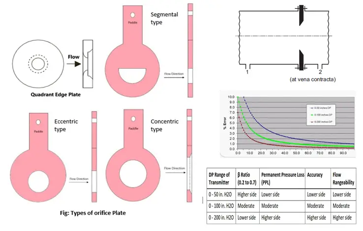
Eccentric orifice plate
Eccentric type orifice plate in which borehole is typically constructed off center, square edged. This type of construction is helpful to prevent the deposition of solid and other unwanted materials present in process fluid on the surface which can block the orifice bore.
The eccentric orifice plate is capable of calculating the flow rate of fluid-carrying gas within the liquid phase (Mixture Phase). The degree of uncertainty is far greater in the Eccentric type in comparison with the concentric type orifice plate.
Concentric orifice plate
A concentric orifice with a center bore design is most commonly used in the application. The concentric orifice plate is a proven and reliable technology that is adopted at the global level. Manufacturing of concentric is also simply by machining a thin plate to create a circular hole in the middle portion of the plate. Concentric orifice plate consisting of a square edge.
Segmental Orifice Plate
In this type of orifice, the plate borehole is centered and consists semicircle shape, with a square edge. Segmental orifice plates are designed for a low amount of slurry and a high amount of solid concentration in the fluid. This type of orifice is an expensive and higher degree of uncertainty in comparison to an eccentric orifice plate.
Quadrant radius orifice plate
This type of orifice plate is designed like a nozzle in which upstream construction is lesser sharp in comparison to the downstream design construction. They are designed for flow containing Reynolds numbers less than 10000 and viscous media properties.
Advantages of Orifice flow meter
- Simple in construction
- Low space requirement
- Relatively cheaper
Disadvantages of Orifice flow meter
- Poor pressure recovery
- Not suitable for low-pressure application
- Higher power loss
Click here to learn about types of flowmeters and their applications