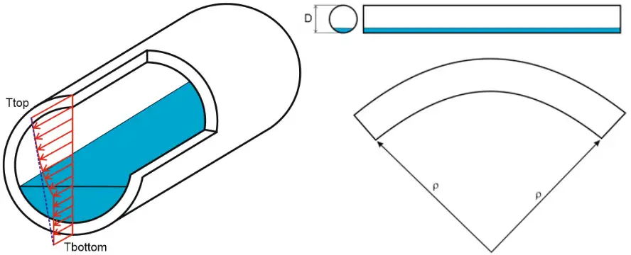
The thermal bowing phenomenon occurs when a horizontal pipe is filled partially by hot or cold fluid (LNG). Many thermal bowing occurrences cause unexpected damage to the piping or supporting structure. Since thermal bowing occurs mostly at transient conditions, such as during startup, the bowing phenomenon may go unnoticed until the damages are discovered.
It can also occur when one side of the pipe is exposed to the sun and the other side is in the shade.
This effect takes place when the temperature difference between the top and bottom of the pipe section is significant. It is called the thermal gradient. This thermal gradient causes pipe thermal strains that produce pipe curvature called thermal bowing.
Assumptions for thermal bowing
The following Assumptions are made for thermal bowing
- Thermal strain distribution across the pipe section is linear
- Applied only for horizontal pipes that meet “horizontal tolerance” criteria |DZ| / ( DX2 + DY2 + DZ2 )0.5 < Tolerance
- Bowing is acting only in the vertical plane
Basics of Thermal Bowing
The thermal gradient can be different for each pipe element. And also it can be different in each operation mode.

The pipe curvature due to the thermal bowing effect:

r – curvature radius
D – outside diameter of the pipe
a – thermal expansion coefficient at operating temperature
Ttop – the temperature at the top of the pipe
Tbottom – the temperature at the bottom of the pipe
Performing Thermal Bowing in Start-Prof
The thermal gradient (Ttop-Tbottom) should be specified in pipe properties.

The thermal bowing effect should be switched on in Project Settings.

The bending moment produced in the restrained pipe due to the thermal bowing effect:

E – pipe elastic modulus at operating temperature
I – the moment of inertia
The operating temperature should be equal to (Ttop+Tbottom)/2
Some more Resources for You…
Stress Analysis using Start-Prof
Stress Analysis using Caesar II
Stress Analysis Basic Concepts
Piping Layout and Design
