
An actuator is a machine component that is used for moving and controlling a system or mechanism. To perform its operation, An actuator needs a control signal and a power source. They are widely used in valves, gates, conveyors, automatic control systems, etc. A valve actuator is a pneumatic, hydraulic, or electrically powered device that supplies force and motion for opening and closing a valve. The actuators can only open and close the valve or enable intermediate positioning. Some valve actuators contain switches or other means of remotely displaying the valve position. They are available in a variety of sizes. Commercial actuators basically perform any of the two functions listed below:
- Operating a device like piping valves or
- Applying a force or torque for lifting, turning, or forming.
Types of Actuators
Depending on the motion that actuators provide to the valves, two types of actuator mechanisms are available:
- Rotary Actuators, and
- Linear Actuators
Rotary actuators produce the rotating motion to operate valves like a ball, butterfly, and plug valves. On the other hand, Linear actuators convert hydraulic, pneumatic, or electric energy into linear motion to operate valves like gate valves, globe valves, pinch valves, etc.
Based on the power source the actuators use, four types of actuators are available in industrial applications:
- Manual
- Pneumatic
- Hydraulic and
- Electric Actuators
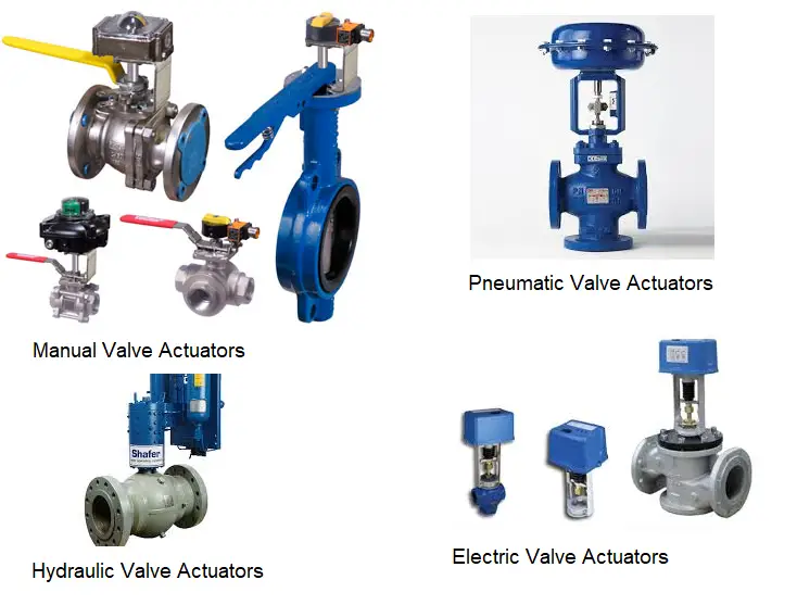
Manual Actuators
Manual Actuators are mechanical devices consisting of hand-operated knobs, levers, or wheels. They are unpowered tools and are used primarily in commercial applications for precise positioning.
Pneumatic actuators
Pneumatic actuators use the energy of compressed air to generate rotary and linear movements to operate valves and dampers. In the broadest sense, an air cylinder is a pneumatic actuator. Most pneumatic actuators use a few standard components which are easy for technicians to maintain
Motion control applications that use rotary pneumatic actuators generally fall in rack and pinion or paddle designs. Double-acting rack and pinion arrangements are often used. Multi-position, three, four, or five-stop actuators are often used for sequential assembly operations. The rotary actuators can also be used for indexing, stepping, picking up, and placing movements.
Pneumatic linear actuators are used in ascending stem valves to directly actuated gate valves, globe, etc. Two types are usually used, the diaphragm and the piston. Membrane styles are popular because their large surface area can generate tremendous force at moderate air pressure. The membrane is a rubber membrane, the edge of which is sealed with the outer housing of the actuator.
The air pressure moves the membrane up or down against the spring pressure, depending on whether the actuator is designed in such a way that it cannot be opened or closed. The stroke lengths are generally shorter than for piston valves, where the strokes depend only on the length of the cylinder and not on the stretch that the diaphragm can tolerate. Piston actuators can be sized to produce an adequate actuation force based on the available air pressure and can be made in double-acting spring return types. Some linear actuators use the familiar air springs instead of membranes. Pneumatic modulating valves are particularly effective because their speed is adjustable.
Advantages of Pneumatic Actuators:
The main advantages of pneumatic actuators are:
- Provides more power than electric actuators.
- An ideal choice for a site with many modulating valves
- Medium fast to fast response. Normally they are faster than most electric motor actuators.
- Safe type of power with a very low explosion risk.
Disadvantages of Pneumatic Actuators:
There are a few drawbacks of pneumatic actuators as listed below:
- The requirement of an air compressor can increase the cost.
- Compressors, dryers, and pneumatic actuators need to be maintained from time to time.
- Leakage can occur at compressed air fittings
Hydraulic Actuators
Hydraulic actuators are devices that use the pressure of a liquid to operate the equipment. The normal liquid is a fire-resistant and stable oil that can work over a wide temperature range. Hydraulically powered devices and systems vary from very simple ones to others that are complex.
Working of Hydraulic Actuators:
All hydraulically operated devices do one of two things:
- move fluid within a space with two or more movable surfaces, like in a hydraulic jack; or
- confine it inside a system where hydraulic fluid is pumped so it can do useful work.
They rely on a basic fact about liquids: the volume occupied by the trapped hydraulic fluid cannot change because it is incompressible. Hydraulic actuators provide more power than any other type of actuator. Also, they provide a faster response and are compact in design. Hydraulic actuators and essential components like pumps, connected pipes, and fluid tanks are often part of a “turnkey” system.
Advantages of Hydraulic Actuators:
- They can generate substantial power
- Fast-acting
- Compact Design
- Depending on the application, hydraulic actuators need to be sized.
Disadvantages of Hydraulic Actuators:
- Frequent maintenance required
- Energy inefficient
- Expensive
- The operation can be noisy
Electric actuators or Electric Motor Actuators
Electric Actuators are electromechanical devices used to remotely control quarter-turn valves such as ball and butterfly valves. Compared to their pneumatic and hydraulic counterparts, electric valve actuators offer a more efficient, cleaner, and quieter method of valve control. They can be purchased as a package with the valve or as a separate unit.
Electric Motor Actuators are self-contained units used to operate a final control element or load. They serve various purposes:
- Convert the rotation of the motor’s shaft to a straight-line movement of a final control element or load through a gearbox, or a mix of gears and linkages.
- Convert the rotation of the motor’s shaft to a lower speed through a gearbox for the final control element or operated device.
- Position the vanes of a damper through a connecting linkage between the motor and the damper. Sometimes more than one linkage is used.
Electric motor actuators have many of the same components, such as a starter and an overload with motor cutoff contacts, that Motor Control Center compartments have for loads like pumps. Most electric motor actuators have external controls such as Open, Close, and Stop push buttons, and a Local-Off-Remote switch.
Common electric valve actuators have a 2-point control or a 3-point control, but both have 3 wires.
Types of electric valve actuators
1. 2 Point Control valve Actuators: The three wires are for +, -, and one control wire. To turn the valve, the control cable must be powered to open and not to close, or vice versa. Without the power to the entire device, the valve will remain in the newest position. For example, JP Fluid Control’s AW1-R series uses this open/close wiring scheme.
2. 3-point control valve actuators: All three wires are for – and two are for +. Therefore, the two control signals can open or close the valve, depending on which one is being powered. The 3-point control also offers the option of intermediate stops (partially open). The two control cables should never be powered at the same time; otherwise, the actuator will be damaged. For example, JP Fluid Control’s AW1 series uses this 3-point wiring scheme
Advantages of Electric Actuators:
- Provides good reliability
- Economic
- Easy installation and operation with negligible maintenance.
- Accurate control mechanism.
- Low power consumption
Disadvantages of Electric Actuators:
- Limited power capability.
- In case of power failure, the valve may not automatically revert to a safe position.
- For larger control loops, they tend to be slower
Pneumatic actuators vs electric actuators
A few points to consider while comparing the pneumatic actuators with the electric valve actuators.
Temperature range:
Both pneumatic and electric actuators can be used in a wide temperature range. The standard temperature range of a pneumatic actuator is -4 to 174 ° F (-20 to 80 ° C) but can be extended to -40 to 250 ° F (-40 to 121 ° C) with optional seals, bearings, and grease. If control accessories (limit switches, solenoid valves, etc.) are used they may not have the same temperature rating as the actuator and this must be taken into account in all applications. In the case of low-temperature applications, the quality must be taken into account and the supply air must be taken into account in relation to the dew point. The dew point is the temperature at which condensation occurs in the air.
Condensate can freeze and block the air supply lines, which can cause the actuator to malfunction. Electric actuators are available in a temperature range of -40 to 65° C. When used outdoors, an electric drive must be sealed off from the environment to prevent moisture from penetrating the internal operation. Condensation may still form inside if it is removed from the power supply line, which may have caught rainwater prior to installation. Because motors heat the interior of the actuator housing during operation and cool when it do not, temperature fluctuations can cause “breathing” and condensation in the surrounding area. For this reason, all the electric actuators used outdoors must be equipped with heating.
Dangerous areas:
It is sometimes difficult to justify using electric actuators in a hazardous environment. However, if compressed air is not available, or if a pneumatic actuator does not have the required operating characteristics, an electric actuator with properly rated housing can be used.
Presentation properties:
Before deciding on a pneumatic or electric actuator for valve automation, there are a few key performance characteristics to consider.
Duty cycle:
Pneumatic actuators have a duty cycle of 100 percent. The harder you work, the better you work. Electric actuators are typically available with 25 percent duty cycle motors. This means that the motor has to be idle frequently to avoid overheating in high-cycle applications. Since most automatic on / off valves remain inactive, 95 percent of duty cycle time is typically not an issue. With optional motors and/or capacitors, an electrical actuator can be upgraded to a pulse duty factor of 100 percent.
Modulate control:
Since electric actuators are gear motors, it is impossible to drive faster without changing gears. A pulse circuit can optionally be added for slower operation. In modulating operation, an electric actuator interacts well with existing electronic control systems and makes electro-pneumatic controls superfluous. A pneumatic or electro-pneumatic positioner is used with pneumatic actuators to provide a means of controlling the position of the valve.
Torque to-weight ratio:
Electric actuators have a high torque-to-weight ratio of more than 4,000 lbf.-in. (450 Nm). Pneumatic actuators have an excellent torque to weight ratio below 4,000 lbf.-in.
Cruise control:
The ability to control the speed of a pneumatic actuator is a key design advantage. The easiest way to control the speed is to insert the actuator with a variable opening (needle valve) into the air pilot’s outlet opening.
How does an actuator work?
It is basically a motor that converts energy into torque. This torque controls a mechanism or a system where the actuator has been incorporated. It helps in introducing or preventing the motion. It runs on electricity or pressure. The control system can be controlled mechanically or electronically, software-driven, or human-operated. They work because of the work done by the rotor and stator assemblies, also known as the primary and secondary windings within the motor. Voltage is applied to the primary assembly which results in inducing the flow of current to the rotor assembly, or the secondary winding. The interaction of these two creates a magnetic field that results in motion.
The working of actuators differs slightly based on their types. Pneumatic actuators work using the pressure of air and hydraulic actuators work using liquid pressure.
A valve drive can simply be defined as a black box with a signal or a power supply via air or oil pressure that creates a stop for the valve movement as an output. The quality of a valve depends on many parameters such as metallurgy, mechanical resistance, machining, etc. The performance of a valve is highly dependent on its actuator. It is important to consider the factors you are considering: frequency of operation, ease of access, and critical features.
Parts of a Valve Actuator
An actuator is connected to and works with two parts: the valve body and the valve pilot.
It consists of several parts including A bonnet, adjusting screw, engine valve spring and diaphragm, vent plug, yoke, upper spindle, clutch block, and drive indicator.
Actuators can automate valves so that no human interaction with the valve package is required to operate the valve. They can be remotely controlled and act as shutdown mechanisms in an emergency that would be dangerous for humans. It is a mechanism for controlling the energy supply. The source can be hydraulic pressure, pneumatic pressure, or electrical current.
Where an actuator should be used?
The actuators are ideal for installations where human interaction is impossible or dangerous, eg. space installation or any location that prevents access to humans as valve actuators.
Compact actuators are used in FPSO or other locations where space and weight are critical. These actuators are designed to offer the powerful torque and thrust of their larger counterparts, but with a smaller footprint to install.
Subsea actuators are designed to withstand the low temperatures, extremely high pressures, and remote access capabilities of subsea equipment.
Ball valve actuators
A ball valve is a shut-off valve that controls the flow of a liquid or gas by means of a rotary ball having a bore. They are characterized by a long service life and provide reliable sealing over the life span, even when the valve is not in use for a long time. They are more resistant to contaminated media than most other types of valves. In special versions, ball valves are also used as control valves.
Types of ball valve actuators
1. Standard:
These are the most common types of ball drives. They consist of housing, seats, a ball, and a lever for rotating the ball. These include ball valves with two, three, and four connections.
2. Hydraulics:
Hydraulic ball valves are specially designed for hydraulic and heating systems due to their high operating pressure and their resistance to hydraulic and heating oil. These valves are made of steel or stainless steel.
3. Flanged:
These valves offer a high flow rate because they typically have a complete connection structure. When choosing a flange ball valve, in addition to the pressure rating, you should also check the compression class of the flange, which indicates the highest pressure that this type of connection can withstand. These ball valves are equipped with two, three, or four connections.
4. Ventilated:
Ventilated ball valves look almost exactly the same in design as conventional 2-way ball valves. The main difference is that when the outlet is closed, it vents to the environment. This is achieved through a small hole drilled into the ball and valve body. When the valve closes, the openings align with the outlet opening and release the pressure. This is particularly useful in compressed air systems where pressure relief provides a safer working environment.
Control valve actuators
The purpose of a control valve actuator is to provide the motive force to operate a valve mechanism.
Types of control valve actuators–
1. Pneumatic control valve: This type has a flexible membrane with pressure applied against the spring force of the actuator. When the control system sends its signal, the actuator generates a force that exceeds the force of the spring and moves the actuator shaft
2. Electric control valve: This actuator has a motor and a gearbox to generate torque that moves the valve up and down. We can find this type in linear and rotary control valves.
3. Electro-hydraulic valve actuator: This type mixes electrical signals and hydraulic units to operate the valve. The signal controls the flow of oil to open and close the valve using a flap nozzle system similar to a pneumatic system.
4. Hydraulic control valve actuator: This works very similarly to a pneumatic actuator and can be used for both linear and rotary control valves. However, it uses liquid instead of air to create force in your system.
How to choose the right actuator?
Selection of the best actuator type for any application is dependent on many factors including:
- Valve type
- Available Power source
- Environment of installation
- Cost
- Operational characteristics and functions like actuation speed, cycle life, the requirement of fail-safe, etc.
Parameters to consider while selecting an actuator are,
1. Valve Size and Torque: Large, high-pressure class valves require high torque to operate. Choosing a very large pneumatic actuator for such a large valve is not economical. In this case, a hydraulic drive is recommended.
2. Failure mode: In contrast to electrical actuators, pneumatic and hydraulic actuators remain in the open or closed position during a power failure. These types of valves are spring-loaded, i.e. in the event of a power or signal failure, the spring returns the valve to a predefined safe position. Therefore, for example, electric actuators are not suitable for shut-off valves that must be completely closed when power is available.
3. Operating Speed - Electric actuators operate valves more slowly than pneumatic and hydraulic actuators. Therefore, an electric actuator may not be suitable if the valve is expected to operate at 1 in / sec or greater.
4. Frequency and Ease of Use: It is common to use electric actuators for certain large valves that are operated frequently rather than manually to facilitate operation. For example, it is proposed to equip a manual 20-inch class 300 ball valve with frequent operation with an electric actuator for ease of use only.
5. Control accessories: In contrast to pneumatic and hydraulic actuators, the control accessories for electric actuators are built into the actuator. In fact, electrical actuators do not require space for control accessories, which is an advantage. Hydraulic actuators have larger control panels compared to pneumatic actuators.
6. Hazardous Areas: In some cases, the use of electric actuators may be restricted in a hazardous environment. Different hazard zones and classes are defined depending on the presence of flammable gases or vapors that can limit the use of electric actuators.
7. Cost: Electric actuators are the cheapest type of actuator, hydraulic actuators are the most expensive, and tires are in the middle.
8. Power Source Availability: A hydraulic actuator cannot be used in a facility if a high-pressure oil source is not available.
This blog is really helpful