
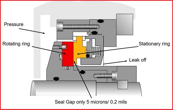
Dry Gas Seals (DGS) are basically mechanical face seals consisting of a mating (rotating) ring and a primary (stationary) ring. During operation, grooves in the mating ring generate a fluid-dynamic force causing the primary ring to separate from the mating ring, thus, creating a “running gap” between the two rings. The running gap varies from 3 to 10 microns depending on the seal type.
A sealing gas is injected into the seal, providing the working fluid for the running gap and the seal between the atmosphere or flare system and the compressor internal process gas.
- Primary Dry Gas Seal: Preventing leakage of working gas from a machine’s inner side.
- Secondary Dry Gas Seal: Backing up the first dry gas seal.
Application of Dry Gas Sealing
Dry Gas Sealing is widely used on
- Compressors for pipelines
- Off-shore applications
- Oil refineries
- Petrochemicals &
- Gas processing plants
Principle of Dry Gas Sealing operation
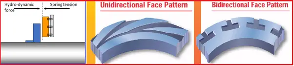
Hydro-dynamic pressure- Tiny grooves cut into the face of the rotating ring scoop gas in between the seal faces creating enough pressure to overcome the tension of the spring holding the faces together.
Gas is scooped into this tight space forcing it to overflow outwards into the gap between the faces forcing them apart
The seals are kept from touching by the generation of hydro-dynamic pressure, created by small grooves cut into the face of the rotating ring which draws gas into the seal, forcing the two surfaces apart.
Because the space between the seals is less than human hair, the sealing gas used must be completely dry and free from grit, dust, or moisture. An external source of sealing gas is therefore used to ensure cleanliness.
The tandem seal system is designed so that after the failure of the primary seal, the machine can be safely shut down using the containment provided by the secondary seal without a hazardous release of gas into the atmosphere.
Although these dry gas seals are able to handle high levels of vibration without damage, reverse rotation of the shaft at high speeds will damage the seals as they are not able to develop the hydro-dynamic pressure required to push the sealing faces apart.
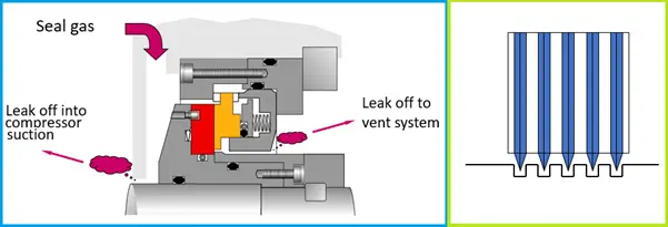
Seal Gas
The supply of filtered buffer gas is injected into the cavity between the primary gas seal and the inboard labyrinth. This supply of gas will leak past the inboard labyrinth back into the compressor which will ensure that the cavity is free from liquids or particles that could damage the gas seal. The supply gas will also leak past the primary gas seal, into the cavity between the primary and secondary gas seals which is directed to an approved vent or flare system.
Labyrinth Seals
Labyrinth seals are used in conjunction with dry gas seals in order to restrict the leakage between chambers around the seal. A labyrinth seal works like a maze, creating a torturous path which the fluid needs to flow through in order to escape
Lubricating oil from the compressor bearings is prevented from entering the dry gas seal by the use of a simple labyrinth seal supplied with separation gas to create a barrier to the migration of lube oil. The labyrinth seals are a “non-contact” type of seal with very fine clearances. Using a system of notches and grooves, the pressure is broken down little, by little so that leakage is minimized (not stopped)
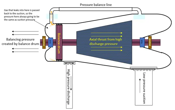
Pressure Balancing
The thrust created by the high-pressure discharge pushing the compressor rotor back towards the suction is canceled by creating opposing thrust using a balance drum.
This pressure balancing system also means the compressor seals are only ever exposed to suction pressure!
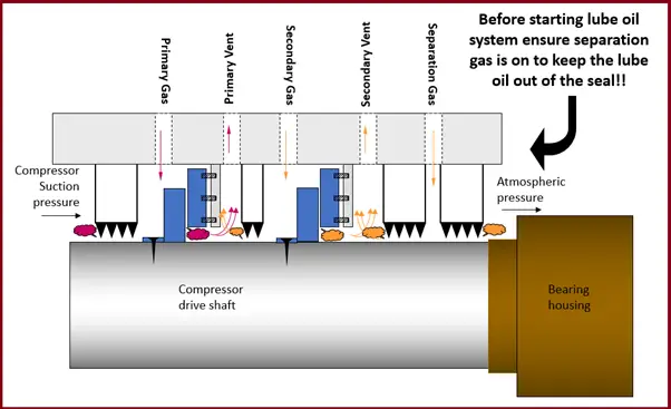
Primary Gas
Primary gas is injected in front of the seal to create a positive flow. It is used to ensure the gas entering the seal is completely dry and clean, completely free from dirt, dust, and moisture.
Secondary Gas
Secondary gas is nitrogen used to provide a clean source of gas to the secondary seal faces. The 2 seals are separated by another labyrinth and the leakage gas is lead to an atmospheric vent in a safe location (above the building)
Separation Gas
Separation gas is nitrogen used to keep lube oil from the adjacent bearing housing from leaking into the dry gas seal system
The typical control scheme for dry gas sealing
A controller maintains a constant differential pressure above suction pressure, while the flows to each seal are also monitored to check seal integrity.
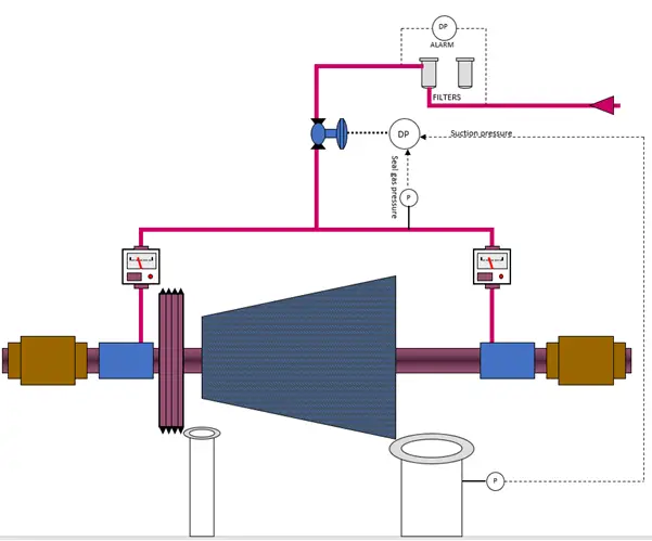
Seal gas vent
- The vent system is kept under back pressure bypassing the flow through a restriction orifice. A secondary path is opened by bursting a ruptured disc to safely vent the higher flows caused by seal failure.
- A differential pressure transmitter monitors the pressure between the seal supply and the low-pressure vent. When the seal is healthy, this dP is high (Primary Seal Gas supply pressure on one side and Flare pressure on the other side). This high dP is used as a start permissive for the compressor. When the seal fails, the dP becomes low, initiating a compressor trip.
- In addition, we measure the pressure in the vent line, upstream of the orifice. In the event of seal failure, this pressure becomes high due to the increased flow to the flare. This high-pressure alarm is also used to trip the compressor.
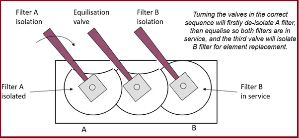
Seal gas filters
It is extremely important the seal gas is clean and dry. A 2-micron fine filter is fitted with a standby element ready for the changeover.
A “smart ring” sequencing system is used to prevent the maloperation of filter valves.
Types of Dry Gas Seals
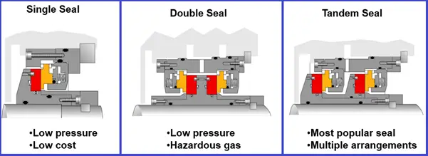
Dry Gas Seals have mainly configured in four types.
(a) DGS Single seal: These seals shall be used where product leakages to the atmosphere are recognized as safe Example: Nitrogen or CO2 compressors.
(b) DGS Tandem seal: Where small product leakages of process gas are admissible. Example: on gas pipeline compressors.
(c) DGS Tandem seal with intermediate labyrinth: These seals shall be used where product leakages to the atmosphere as well as buffer gas leakages to the product are admissible. Example: on H2, ethylene or propylene compressors.
(d) DGS Double seal: These seals shall be used where product leakages to the atmosphere are inadmissible. However, buffer gas leakages into the product gas is admissible. Example: Petrochemical compressors
– Seal on the atmosphere side acting as a safety seal. Tandem seals are mostly used in process gas service mainly in high-pressure and/or hazardous gas applications.
Seal Gas sources: (a) External seal gas & (b) Compressor discharge gas.
Normally the seal gas is injected about 10 psi above the process gas.
Barriers shaft sealing system
It is necessary to avoid allowing the bearing lubrication oil to reach the
seal faces. Barrier gas is injected into the barrier seal chamber to separate the bearing housing
- -In most cases, Nitrogen shall be used as barrier gas for safety reasons.
- A barrier seal is incorporated in the outboard end of the dry gas seal assembly.
Dry Gas Sealing design considerations
(a) Design pressure of seal (static/dynamic)
(b) Process pressure in the compressor at normal operation
(c) Process settle out pressure in the compressor
(d) Pressure of seal gas
(e) Design minimum temperature (static/dynamic)
(f) Design maximum temperature (static/dynamic)
(g) Normal seal gas supply temperature in operation
(h) Filter size seal gas: 3 – 5 microns
DGS Operating Range
- Temp: -140 to +315°C
- Pressure: to 350 Barg
- Speed: to 200m/s
- Shaft: to 350mm dia
Advantages of DGS over Wet seals:
The following can be eliminated
- Process contamination and catalyst poisoning with oil.
- Unscheduled shutdowns caused by loss of control of the seal oil system and/or seal oil pumps/driven failures.
- Lube oil contamination with the process gas.
Things to remember on replacement of oil seals with Dry Gas Seals
The following points shall be thoroughly analyzed prior to the replacement of Liquid seals with DGS.
- Seal chamber dimensions & ports
- Compressor rotor dynamics
- Compressor operating conditions & variations
- Seal gas & barrier gas supply source
- Reverse rotation & surge occurrence
- Idle operations at low speeds
- Maintenance facilities & spare parts availability.
Codes / Standards for Dry Gas Seals
- API 614 – Lubrication, shaft sealing & Control oil system & auxiliaries
- API 617 – Centrifugal compressors for Oil, Gas & Petrochemicals
Dry Gas Seal leakage rates
Seal leakage rates in operation (on-site)
(a) Seal medium: Process gas- Seal leakage rates for seal testing conditions
(b) Seal medium: air
– Expected leakage rates shall always lower the values of guaranteed leakage rates. And outboard leakage rates shall be lower than inboard leakage rates.
Static sealing pressure shall be equal to the compressor casing design pressure.
Acceptance criteria for seal leakage rates
The seal leakage is considered to be stable and acceptable for Stable guarantee points if it varies within +/-5% around an average level.
Gas seal contamination
Liquid drop-out/condensation from the seal gas due to inadequate gas conditioning and filtration
Ingress of raw process gas due to poor gas monitoring and control
Ingress of bearing oil due to loss of separation gas or product failure
Inadequate gas seal monitoring
Outboard (OB) seals are often not monitored:
A failed OB stage can be undetected leading to catastrophic damage to the seal/compressor
If the inboard stage should fail during this situation, it will result in the leakage of untreated process gas into the atmosphere
Improve gas conditioning by one or more of the following:
- Removing liquids from the sealed gas
- Heating the seal gas
- Filtering the seal gas
- Boosting the seal gas
- Improve gas seal monitoring in order to:
- Detect the condition of the gas seal, both inboard and outboard stages
- Ensure no ingress of raw process gas or bearing oil
- Ensure no reverse pressurization
Thankyou so much Mr Anup Day ji for explaining such detailed version of DGS system.
Appreciate your efforys!!!
Dear Anup.
Really a great information you have posted.
Appreciate your time and efforts.
Thank you.
Prasad.omprakash
Thanks for sharing this information. I read lots of article about DGS, but I get the most clarity from this article only.
thanks alot Anup.
appreciate you sharing of this document…
Anup : Good initiation and appreciated the Passion
If possible, include why the compressors or the pumps have to be sealed and what is the necessity which will be very useful for the readers who are starting the career or on learning phase.
It is because, the field is not alone vast but needs patience to understand and surf more.
Hi Anup,
Very good initiative from you. Good piece of information on Dry Gas Seals for compressors.
Regards,
Bejoy
This is really a good information Anup. Currently, Where are you working at the moment?
Very detailed practical explanation, Thanks.