
The flange face is the surface area that receives the gasket. The gasket material seat over the flange faces for creating effective sealing under pressure. The flange faces are designed according to ASME B16.5 for flanges up to 24 inches and as per ASME B16.47 for flanges 26 inches and larger. To prevent leakage problems, various types of flange faces are produced. In this article, we will learn about various types of flange faces and types of flange face finishes.
Types of Flange Faces
The ASME B16.5 and ASME B16.47 standards refer to six different types of flange faces. They are
- Flat face flange (FF)
- Raised face flange (RF)
- Ring joint flange (RTJ)
- Lap joint flange
- Male and female flange (M&F)
- Large and small tongue-and-groove flange (T&G)
Flanges with different faces require different gaskets and should never be mated to prevent joint leakage.
Raised Face (RF)
Raised face flanges are the most common type used in process plant applications and are easily identifiable. It is called a raised face because the sealing face is higher than the circular face of the bolt. This face type enables a wide range of gasket design combinations such as flat ring sheet type, spiral wound type, double wall type, and other metal composite materials.
The purpose of the RF flange is to concentrate more pressure in a smaller sealing area, thereby increasing the joint’s ability to hold pressure. Diameter and height are defined in ASME B16.5 by pressure class and diameter. The pressure level on the flange determines the height of the sealing strip. The typical flange face finish for ASME B16.5 RF flanges is 125 to 250 µin Ra (3 to 6 µm Ra). For pressure classes 150 and 300, the sealing strip height is approximately 1.6 mm (1/16 inch). For pressure classes 400, 600, 900, 1500, and 2500, the sealing strip height is approximately 6.4 mm (1/4 inch).
Flat Face (FF)
A flat face flange has a sealing surface in the same plane as the circumferential surface of the bolt. Flat face flanges should not be bolted to raised face flanges. A soft type (non-metallic) full-face gasket is generally used between two flat-face flanges while making a joint connection. This type of flange face is also known as a plain face. Flat-face flanges are preferred for low-pressure applications. Flat-face flanges are not suggested to mate with an RF flange.
Ring Joint Flange (RTJ)
Ring-type connection flanges are typically used in high-pressure (class 600 and above) and/or high-temperature applications above 800°F (427°C). They have grooves cut into the faces that are steel ring gaskets. As the tightened bolts force the gasket between the flanges into the groove, the flanges seal, deforming the gasket to seal it in the groove, creating a metal-to-metal seal.
The RTJ flange has a raised face with a machined annular groove. This raised surface does not act as part of the sealant. In the case of O-ring sealing RTJ flanges, the raised faces of the flanges that are mated and clamped together may come into contact. In this case, the compressed gasket does not carry any additional load beyond the tension of the bolt, and vibration or movement will not further crush the gasket and reduce the stress in the joint.
RTJ flanges can be sealed with RTJ gaskets in various styles (R, RX, BX) and profiles (e.g. R-style Octagonal/Oval). The most common RTJ gasket is R; styled with an octagonal cross-section to ensure a very strong seal. The “shallow groove” design accepts octagonal or oval cross-section RTJ gaskets.
Lap Joint Flange
The lap flange has a flat side that is not used to seal the flange joint but simply accommodates the back of the stub end. The sealing surface is actually at the stub end itself and can be either flat or raised.
Male and Female Flange
Male and female flanges require adjustment of the flange. The flange face has an area beyond the normal (male) flange face. The other flange or mating flange has a matching recess (female) machined into the face.
The female face is 3/16″ deep and the male face is 1/4″ high, both with a smooth finish. The outer diameter of the female face is used to locate and hold the gasket. Basically, two versions are available; a small M&F flange and a large M&F flange. Custom male and female shrouds are often found on heat exchanger shells to channel and cover the flanges.
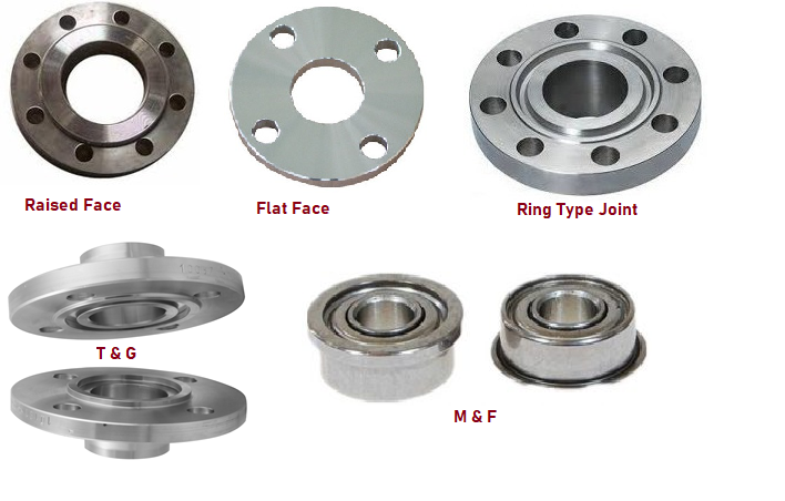
Tongue and Groove Flange
The tongue and groove surfaces of these flanges must match. One flange face has a raised ring (Tongue) machined into the flange face and the mating flange has a matching recess (groove) machined into that face.
Tongue and groove facings are standardized in both large and small. they. They differ from male and female threads in that the inner diameter of the tongue and groove does not protrude into the flange base, thus retaining the seal at its inner and outer diameters. These are commonly found on pump covers and cam covers.
Tong and groove joints also have the advantage of being self-aligning and acting as a reservoir for glue. Blade joints keep the load axis aligned with the joint and do not require extensive machining.
Common flange faces such as RTJ, T&G, and F&M should not be bolted. The reason for this is that the contact surfaces do not match and there are no seals that have one type on one side and another type on the other.
Flange Face Finishes
To ensure that a flange mates with the gasket and the companion flange perfectly, ASME B16.5 requires some roughness on the flange surface area for RF and FF flange finish. The type of roughness defines the type of flange face finish for the flange face surface.
Common types of flange face finishes are
- stock,
- concentric serrated,
- spiral serrated,
- smooth flange finish, and
- cold water finish.
Steel flanges are available with four basic face finishes, however, the common objective of any type of flange face finish is to create the desired roughness on the flange face. It ensures a strong match between the flange, the gasket, and the mating flange for a high-quality seal.
Let’s now learn the most common flange face finish types:
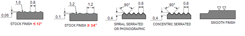
Stock Finish
The most widespread type of flange finish is Stock finish. It suits a large majority of applications. The compressive pressure embeds the soft gasket face into the flange finish resulting in a good seal formation due to the high friction between the contacting faces.
Bolting of the mating flanges squeezes the gasket into the flange face surface and creates a very tight seal.
A stock finish face is produced using a phonographic spiral groove having a 1.6 mm radius round-nose tool with a depth of 0.15 mm and a feed rate of 0.8 mm per revolution. The resulting surface “Ra” values (AARH) range from 125 µinch to 500 µinch (125 µm to 12.5 µm).
Spiral Serrated Finish
Spiral Serrated Surface is a phonographic spiral groove type that differs from the stock surface. The grooves are made with a 90-degree tool (not a round nose tool) that creates a “V” shape with a 45-degree serration angle. The serrated surface is concentric or helical with 30-55 grooves per inch and a roughness of 125-250 microinches.
Concentric Serrated Finish
The grooves are machined using the same 90-degree tooling used for the spiral splines, but the splines have a uniform design on the face of the flange. To create concentric grooves, the tool feed rate is 0.039 mm per revolution and the depth is 0.079 mm.
Smooth Finish
Flanges with a smooth finish will not show any grooves to the bare eye. Tool marks are not visible to the naked eye. Metal-facing gaskets such as the jacketed type make use of this type of flange finish. This flange finish is achieved by machining the contact surface with a continuous spiral groove machined to a depth of 0.05mm with a 0.8mm radius round nose tool at a feed rate of 0.3mm per revolution.
Cold Water Finish
The appearance of the cold water finish is smooth and shiny. The normal range of AARH values for these types of flange surfaces is between 85 µinch to 100 µinch. Metal-to-metal sealing without the use of a gasket requires this type of flange finish.
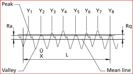
Definition of AARH
The full form of AARH for flange face finishes is arithmetic average roughness height. AARH refers to the flange face’s smoothness/roughness. The AARH values are very important during the flange and gasket material selection process. Higher AARH or “Ra” values signify a more rough surface and vice versa. Specific surface roughness is deliberately generated for specific applications.
The “Arithmetic Average Roughness Height” of AARH is the common indicator for measuring surface roughness. The AARH is defined as the average height of the irregularities on the metal surface, from the mean line. The AARH is measured in micro-inches and denoted by the symbol “Ra”.
Depending on the type of application, there are various standards governing the roughness of surfaces. The name of the equipment used to measure the surface roughness is “profilometer”.
Flange AARH
As the flange face finish plays an important role in the gasket’s reliability and service life, ASME/ANSI defined specific roughness standards for the flanges. According to those standards, the serrated, spiral serrated, and concentric flange face finish should have an average roughness of 125 µinch to 250 µinch (3.2 µm to 6.3 µm).
Specially designed tools with a radius of 0.06 inches (1.5mm) or larger are used to imprint a rough finish on the flange. The groove density on the flange face is usually from 45 grooves per inch to 55 grooves per inch (1.8 grooves/ mm. to 2.2 grooves/ mm.).
When the average flange face roughness is not according to the described standards, the sealing of contacting surfaces would not be properly leading to possible leakage.
Allowed AARH Imperfections
The parameters that govern the sealing performance of the flanges’ gaskets are
- AARH,
- the flange dimensions, and
- the pressure of the stud bolts.
As per the ASME, the adjacent imperfections must be separated by a distance of at least 4 times the maximum radial projection. The radial projection is calculated by subtracting the inner radius from the outer radius.
Note that, the serrations are marked at the same level, and any protrusion above them is not acceptable. These may cause the adjacent serrations to lose hold of the gasket material and may result in wear and leakages.
which standard of flanges describe Flange Face Finishing and which one is better for several temp. and Pressure
thank you