
In our last article, we discussed restriction orifices in detail. The same article also lists the important factors on which the sizing of a restriction orifice depends. Click here to recapitulate those before proceeding with actual RO sizing steps.
Of many kinds of flow restriction devices, restriction orifices (RO) are frequently used, because they are simple and economical devices. RO is applied to regulate the flow rate or pressure. This article will provide the guidelines for the sizing of the Restriction Orifice. It should be noted that this standard practice is applicable to single-phase fluids only.
Inputs Required for Restriction Orifice Sizing
The following is a summary of input data to be prepared for the design of RO:
(1) Operating Conditions
- Flow rate
- Upstream & downstream pressure
- Temperature (for vapor)
- Line Size
(2) Physical properties
- For liquid service: density, vapor pressure
- For vapor service: molecular weight, Cp/Cv, Z-factor, viscosity
(3) Minimum allowable value of cavitation index for liquid service
Output from the Restriction Orifice Design
(1) Single orifice
- Orifice diameter
- The pressure at vena-contracta
- Velocity at orifice
- Calculated cavitation index (for liquid)
- Critical or non-critical (for vapor)
(2) Multi-stage orifice
- Required stage number
- Orifice diameter of each orifice
- Distance between adjacent orifice plates
- Inlet and outlet pressures of each orifice
- The pressure at vena-contracta of each orifice
- Velocity at each orifice
- Calculated cavitation index of each orifice
Principles of RO Sizing Calculation
Flow restriction orifice calculation for Gas Service
Critical Pressure Ratio:
The critical pressure ratio, rc can be obtained from the following equation.
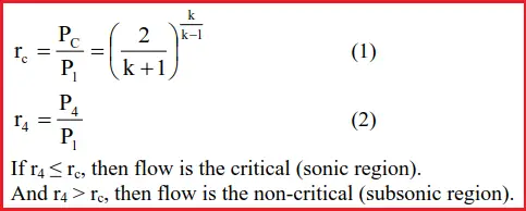
Orifice Diameter:
The equation for orifice diameter should be selected using equation (2), depending on whether the flow is critical or non-critical.
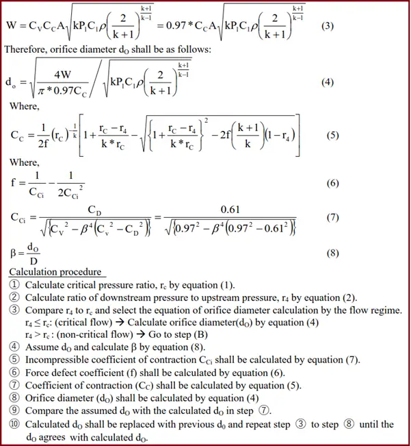
(A) Critical flow (sonic region)- When the ratio of downstream pressure to upstream pressure, r4, is smaller than or equal to the critical pressure ratio, rc, the following equation of orifice diameter for a critical flow should be used.
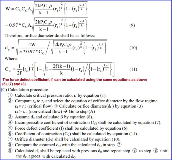
(B) Non-critical flow (subsonic region)- The following equation of orifice diameter can be used for the non-critical flow region.
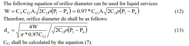
Restriction orifice calculation for Liquid Service:
Orifice Diameter:
Cavitation Index
In order to avoid the cavitation problem, the minimum allowable value of the cavitation index, Kd, should be selected based on the following:
(1) Cavitation index Kd=0.37 shall be used for the usual case. At this critical cavitation condition, the noise is steady but still light. No erosion will occur. (Once the orifice chokes and supercavitation occurs, no damage by erosion will exist near the orifice. This is because the damage is caused by the collapse of the cavities and the collapse occurs far downstream during supercavitation)
(2) On some occasions such as in the following cases, use Kd=0.93 as an incipient cavitation condition in order to avoid severe economical risk.
- Material is high grade such as stainless steel or higher and pipe size is larger than 12”.
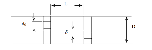
Interval of Orifices
In the case of the multi-stage restriction orifice, the minimum distance, as shown below, should be provided between orifices, to avoid a reduction in RO performance.
- For concentric orifice: L ≥ 5.4*D*(1-β)
- For eccentric orifice: L ≥ D
Deflection Ratio of Eccentric Orifice
The deflection ratio of the eccentric orifice “e” is 0.75.
e = 2δ /(D − d0 ) = 0.75 (14)
Where,
- δ: Pipe center to orifice center length (m)
- d0: Orifice hole diameter (m)
- D: Pipe inside diameter (m)
Restriction Orifice Plate Sizing Calculation Procedure
A. Single RO system-
① Decide the minimum allowable value of the cavitation index to meet a given situation.
- Kd = 0.37: for the usual case
- Kd = 0.93: for the conservative case
② Assume dO and calculate β by equation (8).
③ Incompressible coefficient of contraction CCi shall be calculated by equation (7).
④ Orifice diameter (dO) shall be calculated by equation (13).
⑤ Compare the assumed d0 with the calculated dO in step ④.
⑥ Calculated dO shall be replaced with the previous dO and repeat step ② to step ⑤ until the dO agrees with the calculated dO.
Calculate the cavitation index, Kd by equation (15), and compare it with the minimum allowable value.
If the cavitation index ≥ 0.37 (or 0.93), then the orifice diameter is acceptable.
If the cavitation index < 0.37 (or 0.93), then a single orifice is unable to accommodate the required pressure drop. In that case, a multi-stage orifice system should be applied.
B. Multistage Restriction Orifice Calculation
① Decide the minimum allowable value of the cavitation index to meet a given situation.
- Kd = 0.37: for the usual case
- Kd = 0.93: for the conservative case
First stage orifice: located at the outlet
② Assume upstream pressure of the first stage orifice.
③ Assume dO and calculate β by equation (8) for the first stage orifice.
④ Incompressible coefficient of contraction CCi shall be calculated by equation (7).
⑤ Orifice diameter (dO) shall be calculated by equation (13) using assumed upstream pressure.
⑥ Compare the assumed d0 with the calculated dO in step ⑤.
⑦ Calculated dO shall be replaced with the previous dO and repeat step ③ to step ⑥ until the dO agrees with the calculated dO.
⑧ Calculate cavitation index, Kd, using Equation (15), and compare with minimum allowable value.
If the cavitation index > 0.37 (or 0.93), increase the upstream pressure and repeat the steps from ③ to ⑧.
If the cavitation index < 0.37 (or 0.93), decrease the upstream pressure and repeat the steps from ③ to ⑧.
If the cavitation index equals or slightly bigger than 0.37 (or 0.93), the design of the first stage RO is completed and go to step ⑨.
n-th stage orifice
⑨ Set the upstream pressure of (n-1)-th stage orifice for the downstream pressure of the n-th stage orifice.
⑩ Assume the upstream pressure of the n-th stage orifice.
⑪ Repeat the steps from ③ to ⑧, until the cavitation index is equivalent to the minimum allowable value.
Special Consideration of RO Design:
(1) The minimum hole diameter of RO-
To prevent the plugging problem with RO caused by debris, the hole diameter should be greater than the following values:
- For the clean liquid service: 2mm
- For the clean Gas service: 1mm
When a diameter smaller than the above values is required, the strainer or filter to remove debris should be provided upstream of RO.
(2) The necessity of minimum straight run length-
Basically, the objective of RO is rough control of the flow rate and should not be used for strict control of the flow rate. Therefore, it should not be necessary to take a straight run of piping both upstream and downstream of RO to keep performance. However, for erosional services such as slurry or flush services, countermeasures for erosion shall be considered.
(3) The calculated hole diameter of RO should be rounded to the conservative size for easy manufacturing.
Restriction Orifice Sizing Spreadsheet
A restriction orifice sizing spreadsheet is an electronic tool or software program that helps in calculating the size of a restriction orifice based on various parameters such as flow rate, fluid properties, pressure drop, and pipe dimensions. Often they may come in the form of restriction orifice calculation excel.
Restriction orifices are used in piping systems to control the flow rate of a fluid, and their proper sizing is crucial for the system’s safe and efficient operation. A restriction orifice sizing spreadsheet typically uses industry-standard equations and formulas to calculate the required orifice diameter and other necessary parameters.
The input parameters required for the calculation typically include fluid density, viscosity, pressure, temperature, pipe diameter, and the desired pressure drop across the restriction orifice. The spreadsheet then calculates the required orifice diameter and other related parameters such as Reynolds number, velocity, and flow rate.
The use of a restriction orifice sizing spreadsheet can simplify the orifice sizing process and reduce errors associated with manual calculations. However, it is essential to use reliable and accurate spreadsheet templates or software programs and to validate the results obtained from the spreadsheet against industry standards and guidelines.
Few More Handpicked Learning Resources for you…
The safe way to install restriction orifices
Level Gauges for Industrial Applications
Overview of Piping – Instrument Interface: An article
Basics of Piping Design and Layout
Piping Stress Analysis Basics
Piping Material Basics
Articles Related to Piping Interface Departments
Thanks for the very useful info.
I have a doubt for Multistage RO, Is the flow rate changes after each stage or will it be the same at final stage?
In case If any changes occur, how to calculate the flow rate at each stage?
Regards,
Jagan
Mass flow will always remain same at every stage. Law of conservation of mass will apply.
Thank you for posting this. Can you define what “k” and “C1” are referring to exactly? Also, is this a dimensionless equation? If not, what are the units for length and pressure?
k is the specific heat ratio while C1 is dimensional constant 0.0405 if you are using SI unit or 0.533 for US customary units.
k is the ratio of specific heat. C1 is not defined anywhere. I too want to know about it.
Hi. Thanks for posting.
I have started using RW Miller flow consultant. I need some help understanding the sizing orifice bore in cavitating flow and thick orifice in cavitating flow. How are these method differs in sizing the bore in the sizing of restriction orifice?
Hello,
I am a mechanical engineer that was worked on steam turbines with ABB, ALSTOM & SIEMENS. I graduated 30 years ago.
I was asked to calculate the size of an orifice to reduce steam pressure from 600 psig to 20 psig. Reviewing my old Fluids Book from college I only find stuff for fluids, not steam. Can you direct me to something that deals with steam?
Hello,
Really useful text. What literature did you use to creature this article?
Dear Anup,
I read your blogs on various technical subjects and those are really useful to us. Appreciate your passion about sharing the Knowledge and experience . keep it up.. VYAY KRUTE VARDHTE EVANM NITAYM VIDHYA DHANAM SARVA DHANAM PRADHANAM … More you spend more it will be … that is Knowledge..
Thanks for this useful information.
Question regarding Multi-orifice:
Currently using 4mm orifice in a system to produce a flow of 760m3/h.
The 4mm orifice is prone to fouling and clogging alot.
Will the diameter of the orifices increase when using a multi stage to achieve the same amout of flow?
So it prevents clogging
How do i determine the number of stages in a RO based on the given upstream pressure and overall pressure drop across the RO?
Hi, Thank you for your useful information.
If it is possible to design Orifice in Sonic and Subsonic conditions, which one of the two do you suggest?
Thanks for your useful information
If it is possible to design Orifice in Sonic and Subsonic conditions, which one of two do you suggest?
Thank you for posting this. Can you define what “k” and “C1” are referring to exactly? Also, is this a dimensionless equation? If not, what are the units for length and pressure?
The text is good as well as the formulas but in order to be useful, each parameters has to be defined and the unit in which it has to be used defined. This is critical for any successful calculation otherwise significant errors will results and the whole procedure is useless.
Very good writeup but it appears “Equation 15” to calculate Kd is not defined. This is necessary to complete the analysis of course.
Eqn 15 to find cavitation index is below
Ci = (P1-Pv)/(P1-P2)
where
Ci = cavitation index
P1=Upstream pressure (absolute)
P2= Downstream pressure (absolute)
Pv=Fluid Vapour Pressure
Hope the above equation is useful
Thanks for the write up.
I have few queries.
On what basis the deflection ratio for eccentric orifice is achieved?
What is the out put from that deflection ratio?
Please provide me in detail information regarding above as I am working on same research area.
Regards
Abhishek Talageri
abhicvsit@gmail.com
Please provide reference for formulas used in calculation.
fascinating and helpful article. I could arrive the bore diameter in a RO.
But I could not understand how to arrive number of holes and their diameter, would you explain
Thanks for the info.
Can you provide the reference literature for RO sizing.