
The main function of instrumentation in every process plant is to collect intelligence from the working plant and use those data to control the process parameters as per predefined conditions. Instruments in piping measure different process conditions like pressure, temperature, flow, density, and level as per the process requirement.
Piping engineers have a thorough interface with the instrumentation team for knowing the details of the instruments used. The main responsibilities as part of the instrument-piping interface are modeling these instruments in the 3D models at proper locations and providing appropriate access for operation and maintenance. While pipe-routing, special layout requirements near the instruments for their proper functioning must be ensured.
The instrumentation team provides instrument hook-up drawings explaining how a particular instrument is connected to the piping. The main interface with piping components, special requirements like upstream and downstream straight length requirements, connection types, valve types, access and maintenance requirements, instrumentation-piping scope demarcation, etc are provided clearly in the instrument hook-up drawings. Other deliverables to the piping department from the instrumentation team are:
- Control valve datasheets.
- Preliminary Instrument dimensional drawings and datasheets.
- PSV sizing and reaction forces.
- Panel and Other accessory details.
Piping has a regular interface with the Instruments for
- Scope Break
- Process Connections
- Materials and BOM
- Orientation
The interfaces are mostly standardized. However, these should be discussed with the C&A (Control and Automation or Instrumentation) team at an early stage of the project, preferably.
Some instruments give desired performance when installed in a particular position/orientation. (ex: Coriolis meter). When in doubt the functionality of the instrument should be discussed with the C&A engineer.
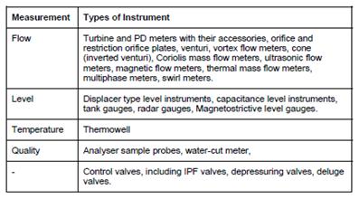
Types of instruments
Instruments in the piping industry can be classified into the following three groups:
- In-line Instruments
- On-line Instruments, and
- Offline Instruments
In-line instruments:
In-line instruments are considered to be all instruments and components direct-mounted in or on process and utility lines or equipment and are subjected to the pressures and temperatures of the piping systems or equipment in or on which they are installed. Examples of a few inline instruments are given below.
On-line instruments:
On-line instruments are all instruments and components connected to process and utility lines or equipment via small (maximum DN 50 or 2 in) primary isolation valves. They are subjected to the pressures of the piping systems or equipment on which they are installed.
Typical examples of online instruments are impulse line components, transmitters, pressure gauges, mono-flange assemblies, analyzer sampling systems, etc.
Offline instruments:
Off-line instruments are considered to be all instruments and components, which are not in direct, contact with any process medium or which are not connected to any process/utility line or equipment
Typical examples of offline instruments are thermocouples, resistance elements, bi-metallic thermometers in thermowell, signal converters, local receiving indicators, etc.
Piping-Instrumentation Interface Salient Points
Some general points which need to be remembered are mentioned below:
- Datasheets for ESD valves if not standardized the Plant ESD valve datasheet must be given to C&A
- Material details for the control valves, Nuts, Bolts, and Gaskets should be considered by piping. Flanges as per ASME B 16.5
- A process-to-instrument valve unit is a means of interfacing between process piping and instrumentation systems.
- Instrument specifications apply downstream the last joint of the last process to the instrument valve or valve assembly, defined for the instrument connection in the mechanical piping class.
- The philosophy is to use single-block valves up to Class 600 and a double block for Class 900 and above.
- If the pipe is insulated, then the design shall incorporate an “over the insulation design” or mount the transmitter remotely.
Flow Instruments:
Flow meters measure the flow. There are various types of flowmeters that can be used in a piping system. Click here to learn more details about flowmeters and their types and applications.
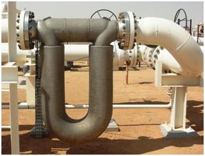
1. Coriolis Flowmeter:
- Should be installed on the downside In Liquid Service and upside in Gas service
- Flow direction should be marked on vendor drawings
- Orientation should be shared with C&A.
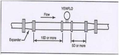
2. Vortex / Ultrasonic Flowmeter / Restriction orifice (Fig. 3)
- Straight lengths should be maintained.
- Tappings on the straight length should be avoided
3. Flow Transmitters / Restriction orifice (Fig. 4)
- Break at the isolation valve ( DBB /SBB).
- The end connection ( instrument side) should be discussed. ( generally threaded)
Analytical Instruments
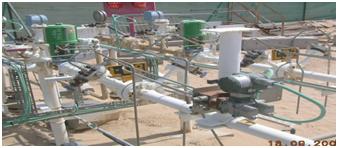
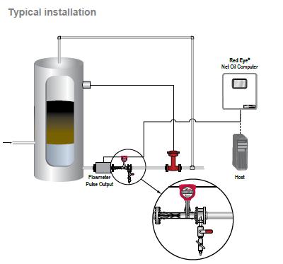
1. Red Eye Meter (BSW meter-Fig. 5)
- Orientation is to be ensured in such a way that the instrument is always flooded.
- Flow direction should be marked on vendor drawings
- Orientation should be shared with C&A
Pressure Instruments
Pressure instruments measure the pressure difference. They are popularly known as Pressure gauges or Pressure Transmitters. Click here to learn more about pressure-measuring instruments.
- Pressure Gauge / Pressure Transmitter-Break at the isolation valve ( DBB /SBB).
Level Instruments
Level instruments are also known as Level Gauges or Level transmitters. Click here to learn more about Level gauges. The main points related to the piping-instrumentation interface for level gauges or level transmitters are:
- Break at the Isolation valve
- Drain / Vent valve under the piping scope
- Level gauge drawings by piping
- Transmitter details by C&A
Temperature instruments
Temperature instruments measure the temperature. Thermowells are the most widely used temperature-measuring instruments in the piping industry. Click here to know details about thermo-wells. The instrument-piping interface’s salient points are:
- Scope break at the flange.
- Gaskets, studs, bolts by piping
your sharing is wonderfull, thank you so much. I am Form Viet Nam
Very good Info, for me from EPC Background