
What is meant by Fluid Flow?
Fluid flow describes how fluid behaves when in motion. It is a vital engineering perspective and studied in hydraulics and fluid mechanics. The theory of fluid flow is very important for effectively sizing piping and equipment.
What is a Fluid?
Any substance which can flow is called fluid. Liquids, gases, or a mixture of both of them are collectively called fluids. They contain a finite mass, occupy a space, and are tangible. They are substances that are either made up of different molecules or particles. They are flowing when the particles of the substance have a change in the relative position concerning time. The properties acquired by the fluids are
- It does have a mass of its own.
- It doesn’t have shapes.
- It occupies the shape of the vessel or pipe where it is flowing.
- It can flow under its weight.
Mechanics is the study of force and its effects. The forces that act on the fluid are
- Surface force
- Body force ( gravitational force)
Fluid Flow inside Pipeline
Flow-through pipes or fluid flow is a type of flow within a closed conduit with a certain pressure. Another type of flow is an open channel flow. These fluid flows are applied to transport chemicals, petroleum products, gas products, sewage flows, household water supply, etc. in different piping and pipeline systems.
The flow of all Real fluids is termed viscous flow (as they possess a viscosity) These properties of viscosity are characterized by the shear stresses or the frictional forces between the fluid layers and fluid to a solid surface, the same as the physical parameters of the pipe & the external force’s affecting the piping system by displacement and loads. The fluid’s flowing and flow parameters affect the piping system in many ways.
How does Fluid flow in Pipes?
Whenever the fluid is flowing, there will be an energy that causes the fluid to flow. There are three different types of energy within the flowing fluid – flow energy (pressure head), kinetic energy, and potential energy. There are basically two causes that make a fluid flow through a pipe.
- Tilting the pipe’s so that the flow becomes downhill, in this scenario where the gravitational energy transforms itself into kinetic energy.
- The second way is to make a pressure difference created through different types of pumps By applying the pressure at one end of the pipe greater than the pressure at the other end. Pumps use impellers, which are connected to the motor to accelerate the fluids into the discharge line. Which makes the flow rate inside the system. The pump doesn’t decide what pressure and flow rate it will deliver to the piping system connected it to.
Pipe Flow Calculations
Flow rates through pipes
The flow rate (discharge) is termed as the volume of the fluid which passes per unit of time, through the pipes. ie, area of pipe*velocity at which fluid flows through the pipe (unit-m3/s).
Types of Fluids
The two types of flow through a pipe can be classified as laminar or turbulent flow. The non-dimensional number, Reynolds number (Re), is used to determine the type of flow-through pipes.
Laminar flow: When the fluid moves slowly in layers in a pipe, without much mixing among the layers. usually occurs when the velocity is low / the fluid is very viscous. The maximum flow will be at the center of the pipes and the minimum flow at the pipe walls. (Refer to the Fig. 1 below)
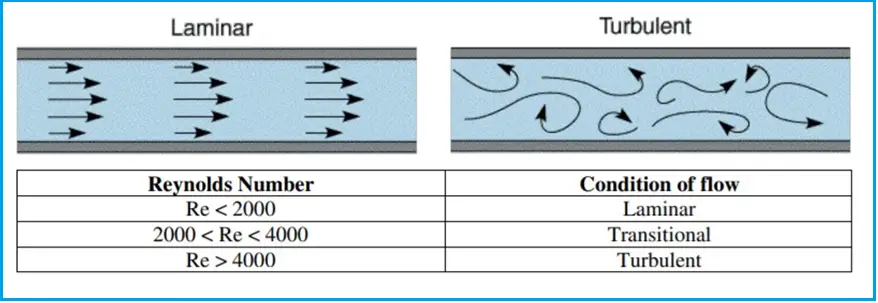
Turbulent Flow: When the velocity of the flow exceeds some threshold value for a given fluid in a pipe, ie. when the velocity is high. flow becomes turbulent, the fluid becomes irregularly fluctuating with time. The velocity at the center of the pipe is approximately equal to the average flow velocity.
Usually, in piping analysis, the flow assurance activities can be founded using the surge analysis software- like the AFT impulse, AFT Fathom, Bentley water hammer, etc. To know the flow rates, pressure, and velocity in piping systems AFT Fathom is commonly used.
Impact of Fluid Properties on Flow through Pipes
The properties of the fluid have a great effect on the piping system where it is flowing.
Considering the density (mass/unit volume), whenever the fluid density is more the mass will also be high making the system compact and dense.
As the viscosity of the fluid increases, we have to adjust the performance of the pumps to equal it up for the additional shear resistance. Usually, there will small reduction in inflow, a more significant reduction in head or pressure, and a sudden increase in power draw.
According to Bernoulli’s principle, as the pressure gets increases the velocity decreases as the pressure and velocity of the fluid are inversely proportional to keep the algebraic sum of the potential, kinetic energy, and pressure constant.
Some of the parameters within the system affect the fluid properties like density, velocity, and viscosity which affect the fluid flow in the piping system.
- Like the temperature change will change the viscosity and density of the fluid.
- The length and the inner diameter. In the case of turbulent flow the internal roughness of the Pipes.
- Position of supply and discharge containers relative to pump position.
- Addition of rises and falls within the pipe layout.
- The number and different types of bends in the system.
- The number of valves and other pipe fittings in the system.
- Entrance and exit conditions of the pipework.
Another important property of the fluid is the specific gravity (relative density) [density of fluid/density of standard fluid]
When we change the specific gravity of the fluid being pumped, the outlet pressure changes in proportion to the change in density. ( lighter fluids create less pressure)
The pressure drop will become unaffected, the hold-up will be increasing due to the effect of surface tension.
Losses in Flow through Pipes
Whenever the fluid flows inside the pipe there will be losses of energy. The losses while flowing through pipes can be classified into:
- Major Losses and
- Minor Losses
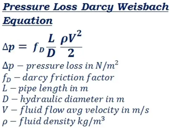
Major losses: This is due to the pipe wall friction; They are frictional resistance forces and are proportional to the volume, depending upon the density of the fluid, nature of the surface, nature of the fluids, and solid wall in contact, and are independent of pressure. Major losses can be calculated by the Darcy Weisbach equation & Chezys formula as given below:
Minor losses: energy losses due to eddy formations in the fluid, caused by the sudden increase (contraction) and sudden decrease (enlargement)of fluid velocity. Due to pipe bends, pipe fittings, and even obstacles.
Gas Flow through Piping System
Gases flow through the piping system in inclined, horizontal & vertical orientations and narrow passages such as chokes for flow control. As per the Joule-Thomson effect when an ideal gas passes by at constant pressure the temperature remains constant, but a pressure drop occurs at some points as the inner energy is transformed into kinetic energy, so as this temperature falls.
Velocity at which the gas flow through a pipe = volumetric flow actual / area of the pipe.
The gas velocity can be derived from the formula for selecting the recommended pipe schedule for the gas flow as per the standards for better gas pipe sizing. The factors to consider for pipe sizing are design flow rate, design temperature, and minimum operating pressure.
Pipes in Series
Pipes are said to be in series When pipes of different diameters are connected from one end to another end to form a pipeline. The total loss of energy (or head) will be the sum of losses in each pipe and the local losses at the connection. The volume flow rate will be constant & head loss is the sum of parts.
The discharge passing through the pipe is the same
Q=A1V1=A2V2=A3V3
The sum of the total head loss in the pipe is equal to the difference in liquid surface levels.
Pipes in Parallel
The pipes are said to be parallel; if the main pipe gets divided into two or more branches, Which again joined together downstream to form a single pipe. Which is connected so that the flow gets divided and comes back together again. In this case,
The Rate of fluid flow (main pipes) = the sum of the Rate of flow(through branch pipes).
Pressure loss across all the branches for the pipe parallel is the same. Q = Q1 +Q2.
Online Course on the Flow of fluids through piping systems, valves, and pumps
Attend this online video course to effectively learn to size valves & piping systems, calculate pressure drop, and flow of liquids & gases through pipes, fittings & valves. Click here to join the course.
Informative content
yours shared documents for upgrading skills of designing pipe line were really entrusting and appreciable it would be glad to share pipe scheme for safe drinking water same information too.
I really grateful and thankful to you sir for sharing and enriching me as it hugely assist me .
great information to work on.