
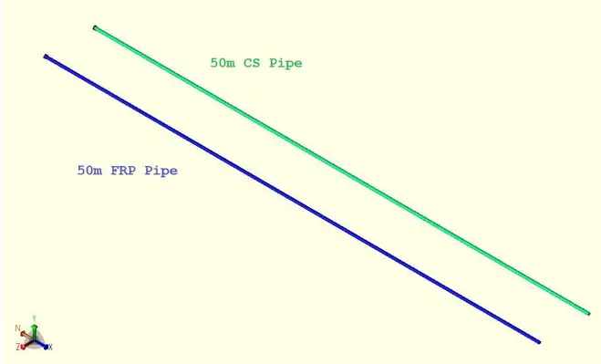
Fiberglass Reinforced Plastics (FRP) pipes, also known as Glass Reinforced Plastic (GRP) pipes, are widely used across various industries, including petrochemical and desalination plants, and can be installed as either above-ground (AG) or underground (UG) piping systems.
When FRP pipes are utilized in AG piping systems, the piping designer must be aware of the inherent differences between FRP and carbon steel (CS) pipes.
This document outlines the differences in thermal elongation between FRP and CS pipes. It examines how these differences influence the design and behavior of the support system in above-ground piping systems. Furthermore, a simple example is presented to demonstrate the impact of these differences. The example is validated through a software-based analysis using CAESAR II.
Coefficient of Axial Thermal Expansion (α)
Thermal elongation is directly proportional to the coefficient of thermal expansion (α). The greater the value of α, the greater the resulting elongation.
∆L = α.L.∆T
This coefficient for FRP pipes is higher than that of CS pipes.
For FRP pipes, α typically ranges between 18×10-6 to 22×10-6 mm/mm/°C, while for CS pipes (e.g., A106 Gr. B), it is approximately 11.5×10⁻⁶ mm/mm/°C.
As a result, FRP pipes exhibit nearly twice the thermal elongation of CS pipes under the same conditions of temperature change and pipe length.
Axial Elastic Modulus (Ea)
Ea for FRP materials is significantly lower than that of steel, typically ranging from 1.5% to 10% of steel’s value, as stated in AWWA M45. Moreover, the thermal load induced in a pipe is directly proportional to both α and Ea.
F = Ea.α.∆T.Ac
Thus, the thermal load transferred to supports due to thermal expansion depends on both the α and the Ea.
Although the α value for FRP pipes is approximately twice that of CS pipes, the Ea of FRP pipes is typically less than 1/10th that of CS pipes. As a result, the thermal loads transferred to supports in an FRP piping system are much lower than those in a CS piping system under similar conditions.
Explanation Example
Note: The values of α and Ea for the FRP pipe used in this example are taken from the datasheet of a biaxial GRP pipe.
- OD=219.075 mm, THK.=8.1788 mm, ∆T=60°C
- Ea(A106 Gr.B)=203.46 GPa, Ea(FRP)=12 GPa
- αFRP=22*10-6mm/mm/°C, αA106 Gr.B=11.95*10-6 mm/mm/°C,
- L=50,000 mm
- Ac=(π/4)(219.0752-(219.075-28.1788)2)=5419.5 mm2
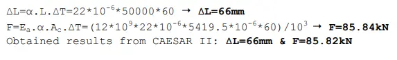
FRP Pipe:
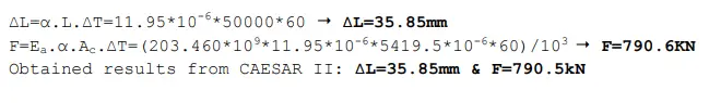
A106 Gr.B Pipe:
Conclusion
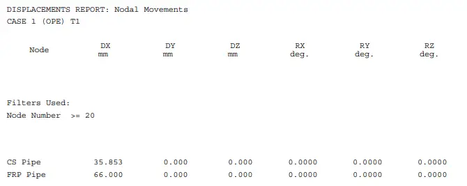
The thermal expansion of a 50-meter FRP pipe is approximately 66 mm, which is nearly twice the thermal expansion of a CS pipe of the same length, calculated at 35.85 mm.
This results in a ratio of 66/35.85≈1.84, confirming that FRP pipes elongate nearly twice as much as CS pipes under identical temperature changes.
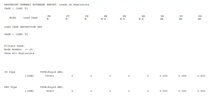
However, the thermal load transferred to supports from the FRP pipe is significantly lower, approximately 85.84 kN, compared to 790.6 kN for the CS pipe.
This means the FRP pipe approximately transfers only 10% of the thermal load transferred by the CS pipe, indicating a reduction of nearly 90%.