Both A312 and A358 are stainless steel materials with ASTM designation having very good corrosion resistance. They are widely used materials for the piping and pipeline industry. In this article, we will find out the basic differences between ASTM A312 and ASTM A358.
What is ASTM A312?
ASTM A312 or SA 312 is an American Standard material specification that covers seamless, welded, and heavily cold-worked austenitic stainless steel pipe. In general A312 pipes are intended for high-temperature and general corrosive service. 304/304L Stainless Steel and 316/316L Stainless Steel are the most widely used grade of A312 specification.
What is ASTM A358?
ASTM A358 or SA 358 is a material specification for electric-fusion-welded austenitic chromium-nickel stainless steel pipe. A358 stainless steel materials are widely used in high-temperature and or corrosive service industrial applications.
Applications of A312 and A358
As stainless steel pipes of Specification A312 and A358 are corrosion resistant, they find wide applications in harsh conditions. In corrosive environments, both A358 and A312 proved their durability. Additionally, They have good low-temperature resistance capability. Because of all these, the popular industries that use A312 and/or A358 materials are:
Chemical, Petrochemical
Mining
Food and beverage
Oil and gas
Marine
Pharmaceutical
Power generation
Renewable energy
A312 vs A358: Differences
Even though both A312 and A358 represent Stainless Steel materials for piping and pipeline industries having similar compositions and applications, there are some differences between the two alloys. The following table lists the major differences between ASTM A358 and ASTM A312.
ASTM A312
ASTM A358
ASTM A312 materials are manufactured by Seamless without welding, Automatic Welding without filler material, or heavy cold working.
ASTM A358 materials are manufactured by fusion welding using single-welded or double-welded butt joints.
A312 materials have different grades and no sub-classes.
Depending on the type of welding, filler material requirement, and radiographic requirements they have 5 sub-classes within A358. They are designated as class 1 to class 5 and must be mentioned while ordering.
A312 material conforms to the requirements furnished in Specification A999
While A358 SS pipes conform to the requirements provided in A240.
Seamless A312 SS pipes are usually costly.
A358 pipes are usually cheaper.
In general A312 pipes are manufactured for a size up to 30 inches
A358 pipes are usually manufactured up to a size of 48 inches
Table: A358 vs A312
What is a Progressive Cavity Pump? Its Working, Design, and Applications
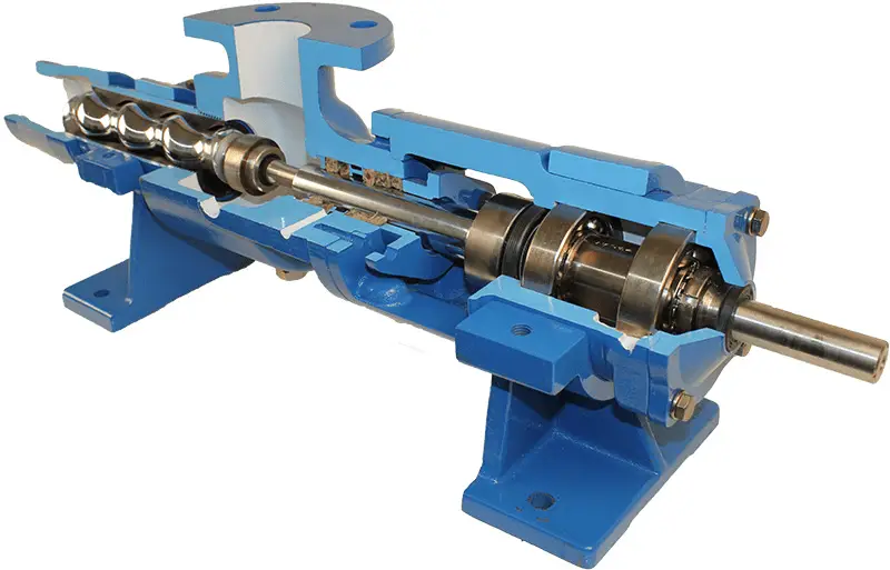
A progressive cavity pump is a positive displacement type pump mainly used for handling high-viscous fluids and tough pumping applications. They are also known as cavity pumps, progressing cavity pumps, PC Pumps, progg cavity pumps, progressive cavity screw pumps, or eccentric screw pumps. As the pump transfers fluids by means of the progress of fixed discrete cavities through the pump when the rotor turns, it is known as a progressive cavity pump. It is a versatile pump having various applications to handle abrasive, high-viscous fluids. In this article, we will learn the working, design, applications, advantages, and disadvantages of a Progressive Cavity Pump.
Working of a Progressive Cavity Pump
Progressive cavity pumps consist of a helical rotor and a twin helix stator. The pumping fluid enters the pump through the inlet suction nozzle. The fluid is then fed into a long casing having the helical rotor and stator assembly. When the rotor turns and contacts the stator surface, a series of small cavities are generated in between. The pumping fluid is progressed through these cavities and is finally expelled through the outlet. The sealed cavities are the main cause of the transfer of the fluid.
Progressive cavity pumps are not allowed to run dry as the heat generated by the rotor and stator may cause pump failure. They are self-priming pumps with higher pressure per stage and high suction lift. The working theory of progressive cavity pumps is invented by René Moineau, a pioneer of aviation, in 1930.
Design of Progressive Cavity Pumps
The rotors of the PC pump are usually made of Steel with a smooth hard surface coating and the stator is usually made of a molded elastomer inside a metal tube body. The complex cavities are formed in the elastomer core of the stator. Angled link arms and bearings allow the rotor to roll around the inner surface of the stator. There are two designs of stators in a cavity pump. They are equal-walled and unequal-walled. The unequal-walled stator design has a greater elastomer wall thickness at the peaks. Because of the increased ability of the stator to distort under pressure, the large-sized solids can pass through the unequal-walled designs.
Fig. 1: Typical Progressive Cavity Pump
Other pump components like pump body, joints, driver, coupling, connecting rod, bearing, packing, sealing, etc are common for all types of pumps.
Applications of Progressive Cavity Pumps
Progressing cavity pumps are used in a range of industries specifically for handling high-viscous fluids and slurries. Some of the common applications of PC pumps are:
Sewage and sludge pumping
Oil pumping
Grout or cement pumping
Food and drink pumping
Coal slurry pumping
Limited energy well water pumping
Mining slurry pumping
Viscous chemical pumping
Stormflow screening
Transferring paint, varnish
Oilfield directional drilling
Pumping cosmetics, creams, and lotions
Marine diesel fuel pumping
Lubrication oil pumping
Transferring shear-sensitive fruits and vegetables
Specifically, they are used for the purpose of pumping, dosing, and metering chemicals, shear-sensitive materials, and heavy-viscous fluids. The industries that make frequent use of progressive cavity pumps are:
Wastewater industry
Oil Lubrication industry
Chemical manufacturing industry
Cement industry
Sewage treatment plants
Food and Beverage industries
Pulp and Paper industries
Oil Drilling Industries
Petroleum production, etc
Advantages of Progressive Cavity Pumps
Progressive cavity pumps have several advantages like
They are suitable for solids and other difficult mediums.
They can easily handle multi-phase fluids, air-entrained fluids, and abrasive fluids.
They provide good precision in dosing.
PC pumps can provide continuous, gentle, and low pulsation flow.
They are self-priming
They do not create vapor locks.
They have a high suction capability.
Accurate to act as a metering pump.
Reverse rotation and flow are possible.
Quiet operation.
PC pumps can be operated vertically.
Disadvantages of Progressive Cavity Pumps
However, there are certain drawbacks of Progressive cavity pumps. The main disadvantages of Progressing cavity pumps are
PC pumps can not run dry. They need a lubricating fluid film for their operation.
They usually are slow-moving with less flow amount.
Their pumping capacity is limited. They can pump up to a limited distance.
When slippage occurs between the rotor and the stator, the efficiency considerably decreases.
FAQs of Progressive Cavity Pumps
Is the progressive cavity pump the same as the screw pump?
A screw pump also has rotors and is quite similar to PC pumps. But the main difference between a screw pump and progressing cavity pump is the application. While screw pumps are used specifically for nonabrasive fluids, Cavity pumps are used mainly for abrasive fluids, slurries, etc.
Can progressive cavity pumps pump water?
Progressive cavity pumps are normally used for sheer sensitive and highly viscous liquids like slurries. For less viscous liquids like water, PC pumps are usually not used.
Are progressive cavity pumps reversible?
yes, progressive cavity pumps can operate in either direction with equal efficiency.
Can the progressive cavity pump run dry?
No, Progressive Cavity Pumps cannot be run dry. If it is run dry then the heat generated will damage the stator. That is why dry-run protection devices like stator temperature probes are used.
How do you prime a progressive cavity pump?
PC pumps are usually self-priming pumps. The Priming of cavity pumps can be done by filling the pump with the medium to be transferred. Priming of pumps is essential for proper lubrication of the rubber stator.
SmartPads System: Protection Against External Pipeline Corrosion Under Pipe Supports
There are no better alternatives to piping and pipeline systems for carrying fluids. But most piping and pipeline systems are subjected to corrosion which reduces the life span and sometimes creates failures. Corrosion is one of the major threats to both piping and pipeline systems. There are two types of piping corrosion; Internal corrosion by the fluid and external corrosion by the environment and thermal effects. Internal corrosion is usually compensated during the design stage by considering extra pipe thickness or by providing internal lining. However, most of the time the external pipe and pipeline corrosion remain unnoticed. In this article, we will explore more about external pipe and pipeline corrosion and some of the means to prevent/reduce external corrosion.
Piping systems are usually designed for a life span of 20 to 25 years and pipeline systems for 10 to 40 years. To ensure that the system works smoothly throughout its design life, the pipe must be protected from corrosion. There are ways by which the extent of external corrosion can be reduced.
The pipe external corrosion that occurs in a pipe or pipeline system can be categorized into two groups.
Pipe external corrosion due to Prevalent Environmental Condition
External pipe corrosion on pipe support points due to rubbing (friction) during pipe thermal growth.
In this article, we will learn about corrosion under pipe supports.
Corrosion Under Pipe Supports (CUPS)
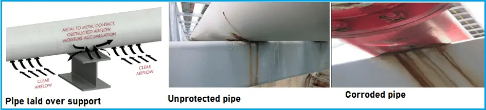
An industrial piping system typically rests on supporting structures at intervals predetermined by engineering specifications. These supports can be made from concrete, steel, wood, etc. Such piping systems often vibrate and move due to expansion and contraction (both seasonally and between day and night), rotating equipment such as pumps and compressors, fluid flow, etc. As a result, and due to the physical contact between a pipe and its supporting structure and these types of movements, these contact regions or points often rub and scratch off a pipe’s protective coating. Over time, this removes that protective coating entirely, leaving expensive piping bare and exposed to the elements such as humidity, heat, salt, oxygen, etc.
There is a reduction in airflow in the area where the pipe and support meet, which causes moisture to remain for longer periods. As a result of all these factors, corrosion starts to set in.
Once a pipe starts to corrode, corrosion cells slowly but steadily spread, eating the pipe from the outside in, until it punctures and chemicals leak out, causing lost assets at least, and catastrophic failure and the loss of life at worst.
Fig. 1: Corroded under pipe supports
Solving this problem typically involves either protection or inspection and remediation. Inspection can be costly, while remediation oftentimes involves line shutdown and safety hazards, in addition to the actual cost of remediation. Proper protection eliminates this problem before it occurs. To protect piping systems from corrosion, numerous solutions have been developed over the past few decades, with varying degrees of success, failure, and cost.
Existing Solutions for Corrosion under Pipe Supports
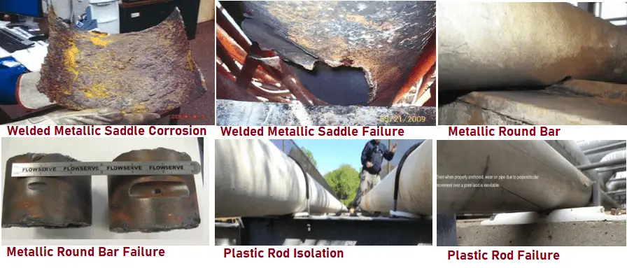
Numerous attempts have been made over the past few decades to protect piping systems from corrosion at the pipe support contact points (CUPS). Metal wear plates that cradle a pipe are either fully welded or tack-welded to a pipe at these contact regions to protect them from friction, and they can be an effective solution.
However, these metallic types of saddles do not stop corrosion, not to mention that the installation process requires line shutdown and welding permits, which would halt production for the duration of the procedure. Metallic wear pads can also become a safety hazard if moisture is trapped in crevices between the pad and the pipe, causing the formation of hidden corrosion cells.
Metal round bars have also been used to raise pipes above their supports to promote airflow. However, such bars point-load the pipe and cause increased stress at the point of contact. This causes more problems than it solves. Their plastic counterparts often fail and break off, or simply cause the same point-loading and damage.
Fig. 2: Examples of Corrosion under pipe supports
Rubber, Neoprene, TEFLON, and PTFE flat sheets are sometimes wrapped around a pipe in those regions to isolate it from its supporting structures. However, these sheets often slide off, fall off, or are torn apart due to high friction forces, thus exposing the pipe to the elements again. In the end, they all lead to corrosion.
All these solutions, including traditional FRP, wear pads that cradle a pipe and use epoxy to be fastened to a pipe, usually require special inspection procedures to verify their effectiveness over time. Inspection devices and processes, including X-Ray, EMAT, radar, lasers, etc., are costly. Lifting pipes and recoating them at these weakening points is even more costly.
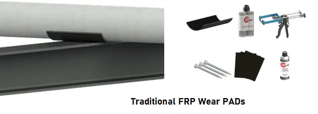
Traditional FRP Wear Pads
Since the design of the SmartPads resembles that of epoxied-on FRP wear pads, we will give these pads a bit more attention and discuss their strengths and weaknesses in greater detail. Epoxied-on, or glued-on, FRP wear pads are a proven and effective solution to combat Corrosion Under Pipe Supports. The pads effectively separate and support the contact region of a pipe without point loading and damaging the pipe over time.
They offer advantages over their metallic counterparts in that there are no metallic components, and as such, they do not require welding permits or line shutdowns.
Fig. 3: FRP Wear Pads to solve CUPS
However, FRP wear pads do have a few drawbacks, especially when compared to SmartPads design, as follows:
The installation process is laborious and can take 15 to 60 minutes, depending on the experience of the installer and various environmental factors.
Thorough and meticulous pipe surface cleaning and roughening are required for the epoxy to properly adhere to the pipe.
The installation process requires an additional 24 hours of cure time for the epoxy to effectively bond the pad to the pipe.
The epoxy must fully cover the inner surface of the pad, and a sealing perimeter bead of epoxy around the entire pad is also required to prevent water molecules from entering the pad/pipe interface. Dirt and other impurities, as well as imperfect workmanship, can all allow water molecules to enter between the pad and the pipe, rendering the pads useless in protecting pipes from corrosion. Replacing or repairing damages caused by trapped moisture can cost thousands to millions of dollars.
The use of epoxy is particularly cumbersome and messy in the summer and can be almost impossible to use in extremely cold weather conditions.
Faulty installations are possible; installer experience is critical.
The process requires several components to be maintained on hand.
The process may require a paint touchup afterward.
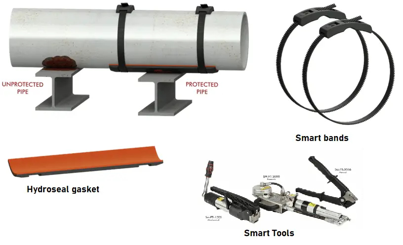
The SmartPads System
The SmartPads System is an innovative solution made from components and materials that have been on the market for many years. However, these components have either been redesigned or are combined in a new and innovative manner to better solve the CUPS problem, at a fraction of the overall cost of competing solutions. Some components are used as-is, while others required some intelligent design modifications to suit the problem at hand and to create a better and more effective pipe corrosion protection solution.
In short, the SmartPads System protects piping systems from CUPS in the following manner:
The SmartPads themselves are all-composite FRP wear pads with special design modifications, including two recessed grooves to allow SmartBands to sit recessed into the pad’s body. The recesses anchor the bands firmly in place while protecting them from being damaged by the pipe support.
A closed-cell Hydroseal gasket is pre-installed on the inner surface of each SmartPad. These gaskets are capable of offering NEMA 4 watertight seal when compressed.
The SmartPad, with its Hydroseal gasket, is placed underneath the pipe at the pipe support point to isolate it from its supporting structure and to protect it from wear.
Composite SmartBands are looped around each SmartPad into the recessed grooves, and composite buckles are attached to the SmartBands.
The smart tool is then used to apply a high rate of tension to tighten the SmartBands, thus compressing the Hydroseal gasket. This, along with the pipe’s compressive load, creates a NEMA 4 water-tight seal, effectively eliminating the possibility of moisture ingress between the pad and the pipe.
Finally, the built-in clipping mechanism of the SmartTool is used to cut off excess banding.
The installation process takes only seconds.
The SmartPads can be removed, in seconds, by cutting off the SmartBands to visually inspect the pipe. They can then be reinstalled, again in seconds, using the original SmartPad and gasket.
The SmartPad’s body will also protect the pipe’s surface from friction at the contact region, thus preserving the pipe’s protective coating.
SmartPads System Components
The SmartPads System consists of four main components, as follows:
Composite (FRP) SmartPad
Hydroseal Gasket
SmartBand & Buckle (all composite)
Smartwool
Chemical Resistant Option: Teflon Strips
1- Composite (FRP) SmartPad
The SmartPads are made from a true Laminated Vinyl Ester Composite material. They are designed, manufactured, and tested specifically to be used as pipe supports. The composite material consists of many layers of continuous strand mat laminate (see below), impregnated with top-quality vinyl ester resin.
Most manufacturers of FRP wear pads re-purpose low-cost filament wounds FRP duct or FRP pipe/tubing. These are designed to carry corrosive internal media but were never designed to be used as pipe supports.
The SmartPad’s fiber-reinforced composite material has a high load capacity rating and a low friction surface. This allows the SmartPad to effectively support and protect a pipe as it slides over a beam or support location. The composite material is UV stable and load tested to ensure peak performance in the most demanding applications such as marine, off-shore, and other highly corrosive environments.
2- Hydroseal Gasket
The SmartPad’s Hydroseal gasket is the key component for preventing water molecules from entering the interface between a pad and a pipe to cause corrosion. The gasket consists of a closed-cell structure resembling a memory foam mattress for pipes. Once compressed, the gasket conforms to the pipe’s outer surface, effectively dampening vibration and improving impact resistance.
The key feature of the Hydroseal gasket is the watertight NEMA 4 seal it creates, when it compresses, between a pipe and the SmartPad’s exoskeleton. This solves the prevailing problem associated with FRP wear pads and similar solutions that depend on epoxy to create a watertight seal. The gasket system eliminates the chances of moisture getting trapped between the pad/pipe interface. Once moisture is taken out of the equation, a corrosion cell cannot form. Installer error in an epoxied-on system could lead to moisture traps and severe crevice corrosion issues that could remain hidden and undetected for years; a problem the patented system remedies.
3- SmartBands
The SmartBands are used to fasten SmartPads to pipes. SmartBands are heavy-duty, continuous-strand fiberglass-reinforced polymer straps that do not have any metallic components or parts. When the bands are tensioned using the SmartTool, they will be securely fastened and will not slip or fall off. The only way to remove them is to cut them off. A large amount of tension, combined with the weight of the pipe itself, will cause the Hydroseal gasket to become compressed. This creates the NEMA 4 watertight seal that prevents water molecules from collecting between the pads and the pipe, which causes corrosion (CUPS) over time.
Fig. 4: Smart Pad Systems
The teeth on each SmartBand will prevent the release of tension over time. This means the NEMA 4 seal will remain as long as the SmartPad is installed, and for the duration of its lifecycle, between 20 and 30 years, and possibly more.
4- SmartTool
The SmartTools is specially designed to tighten the SmartBands, which in turn fastens the SmartPads to the pipe with the necessary tension to be retained for the lifetime of the system. The tool, in all its variants, is capable of creating more than enough force to compress the Hydroseal gasket to create a NEMA 4 watertight seal, without even factoring in the weight of the pipe itself. This mechanism prevents corrosion from ever forming between the pad/gasket and the pipe.
The tools are made from high-grade composite and metallic materials capable of applying high rates of force without damage or deformation. Their design entails ergonomic hand grips, for both convenience and proper operation. A built-in mechanism to cut off excess banding is included, for both convenience and speed of operation.
SmartTools come in three varieties: Manual for quick operation, mechanical for precise application of specific force ratings per engineering standards, and pneumatic for quick installation of large numbers of SmartPads.
5- Optional: TEFLON Strips, Chemical Resistant Option
Some chemical processes involve highly corrosive materials that may damage the SmartPad or the Hydroseal gasket. As such, a TEFLON strip can be applied to the perimeter of the Hydroseal gasket to protect it as well as the edges of the SmartPad from such corrosive chemicals. A wide variety of materials can be utilized for this purpose, with TEFLON being the most common. This strip is represented by the white material at the perimeter of the model.
SmartPads System Benefits
The SmartPads System is the latest of many competing solutions designed to solve the expensive problem of corrosion under pipe support (CUPS). While each solution has its pros and cons, the SmartPads System offers numerous advantages and benefits that no other solution offers or combines. Among such benefits are:
Heavy-duty, all-composite material
Eliminates metal-to-metal contact
Prevents external corrosion in piping systems at the pipe support points
Epoxyless SmartPads offer effective corrosion protection benefits without the problems associated with epoxied-on FRP wear pads
Installs in seconds
Quick removal and reinstallation
Allows visual inspection for corrosion, in seconds
100% install success rate
NEMA 4 watertight seal between pipe and pad/gasket
Removable: In seconds, allowing future visual inspections at reduced labor costs (approx. half the overall cost)
Reusable: Cost-effective and green solution
Versatile: Offers a wide range of gasket materials to meet specific applications, including corrosive chemicals resistant options
Dampens vibration and noise
Installs on live lines
No welding permits or line shutdown required
-60°F to 400°F (-51°C to 204°C) operating temperature
Speed of Installation
The SmartPads System has no viable competitor when it comes to ease and speed of installation. The pads install in seconds, while other solutions entail the long processes of welding or the application of epoxy or adhesives. For example, epoxied-on FRP wear pads can take 15-30 minutes to install, plus an additional 24 hours or more of epoxy cure time, depending on ambient temperature, humidity, and other environmental factors. Installer experience also plays a major role in the successful installation of these pads. The SmartPads System does not require any cure time. Also, installers are not required to perform any touch-up work to seal the pad to the pipe, since no epoxy is involved. Furthermore, the self-sealing Hydroseal gasket is designed to reduce the risk of a faulty installation, making the system even safer and more efficient.
Additionally, and in the rare occasion a SmartPad, for one reason or another, is installed incorrectly, or installed at the wrong location, it can be easily removed and re-installed, with minimal time and cost requirements. The same applies if a SmartPad must be removed for visual inspection purposes; this process will only take seconds. Epoxied-on FRP wear pads cannot be removed once the epoxy cures, even for inspection purposes, unless chiseled off. Welded metallic wear pads will be even harder to remove.
SmartPads in Operation
The SmartPad System has been in service since 2018 in facilities near the Gulf of Mexico. Currently, a few major customers are deploying the system in pilot programs, for both assessment purposes and full adoption. Among those customers are Chevron, Formosa, and Nutrien, all located in the Gulf of Mexico or near coastal regions. Further information about smart pads systems can be found by clicking here
Online Video Courses on Piping Support
To learn more about piping support design and engineering you can opt for the following video course.
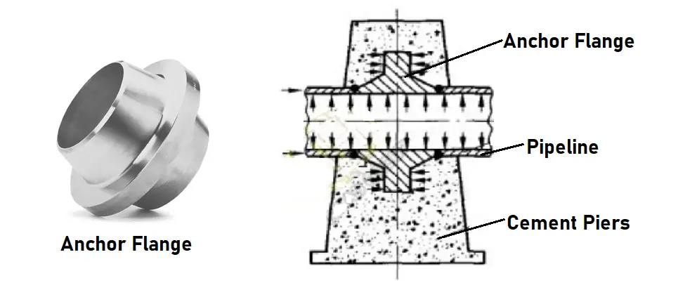
An Anchor flange is a forged fitting that looks like a weld neck flange with shape. It resembles a pipe flange but acts as an anchor in pipelines. This is the reason they are popularly known as Anchor Flange. Anchor flanges are embedded inside reinforced concrete blocks and are specifically used in pipelines to limit the thermal expansion/contraction forces and thrust forces. The weight of an anchor flange is usually estimated according to two weld neck flanges of the same size.
Uses of Anchor Flanges
Anchor flanges in pipelines are installed in various ways. Some of the typical locations for installing anchor flanges are:
points of directional change
suction and discharge laterals of the pumping station at a river crossing
connections to equipment at meter run
to secure subsea piping and risers to the platform structure
Anchor flanges immobilize the pipe at predetermined locations decided by pipeline stress engineers and transfer built-up stresses to external structures. The use of anchor flanges protects equipment and valves from very high stresses that could be generated due to the temperature and pressure of the line.
Features of an Anchor Flange
The concrete that embeds the anchor flange must be designed considering the loads for the worst operating scenario. Normal practice is to calculate the anchor flange loads using pipe stress analysis software.
Anchor flanges are supplied with end weld bevels that match the pipeline wall thickness. Widely used materials for anchor flanges are SA 105 and high-yield stress such as SA 694, F52, F60, F65, and F70. In general, the sizes of anchor flanges range up to 42”, however, larger custom sizes can be available. Each anchor flange is designed following the rules mentioned in ASME VIII Div.1 with the data taken from the process datasheet supplied by the customer.
Fig. 1: Anchor Flange
For large-diameter, high-pressure, and long-distance oil and gas pipelines, anchor flanges act as important supporting members. They are normally placed underground or buried.
An anchor flange is a type of flanged axisymmetric ring body. Both sides of the flange are symmetrical flange necks. The ends of the two flanged necks are each welded to the end of the pipe and embedded in the anchor pile. The two flanges are connected by bolts, combined with existing technology, the gasket is removed, and the flange is connected to the gas transmission pipeline by welding to create an integral flange, which is fixed by the flange body and the anchor pile. Can be used for pipeline connection repair.
Anchor Flange Dimensions
Dimensions of anchor flanges are obtained from ASME B16.5. The anchor flange dimensions vary with respect to the pressure class and size of the pipeline. In general, all dimensions including thickness increases when the pressure class increases for the same size of the pipeline. Again, the anchor flange dimensions increase with respect to the increase in pipeline sizes for the same pressure class.
Ordering Information for Anchor Flanges
The following information must be provided while ordering an anchor flange.
In normal day-to-day operations, we always find terms like steam condensate, gas condensate, oil condensate, and so on. So, the term condensate is widely used in the oil and gas industries. In this article, we will explore the meaning of Condensate, its definition, generations, and implications.
What is a Condensate | Condensate Definition
Condensate is the final liquid product produced by condensation. Whenever any vapor or gaseous phase condenses it produces condensate of that product. So, condensation is mainly related to vapors and gases. For example, the condensation of steam produces steam condensation. In a similar way, the product produced by the chemical condensation reaction is known as chemical condensate.
Condensate is a generic term widely used to describe the liquid phase generated from gas/vapor condensation. Normally the condensate coexists with the gaseous phase and produces a two-phase mixture. Again, condensate can form by condensation of a mixture of a variety of very low-density, very low-viscosity, liquid hydrocarbons along with natural gas. Depending on the product from which they are generated condensate is sometimes termed natural gas condensate, steam condensate, condensate water, etc.
Condensate is formed when the latest heat from any gas, vapor, or steam is removed by chemical reaction or by contact with other cold surfaces.
Properties of Condensate
The important properties associated with any condensate are:
Molecular Weight: Calculated as a function of the molecular weight of the individual components.
Density and Specific Volume
Specific Gravity: Calculated as the ratio of the condensate density to the density of water at the same pressure and temperature. Gas condensate usually has a specific gravity ranging from 0.5 to 0.8.
API gravity specifically for Petroleum products (Oil condensate has an API gravity ranging from 45 to 70).
Surface tension to measure the extent of energy stored at the condensate surface.
Depending on the source and the process the condensate is generated, the composition of condensates varies. The appearance of condensate also varies from colorless to yellow or brown.
Typically, petroleum condensates are composed mainly of saturated hydrocarbons like butane, pentane, hexane, etc. They usually contain low Polycyclic Aromatic Hydrocarbons which are generally found in crude oils. Oil condensates have a very low solubility in water but are highly volatile. Due to the low density of petroleum condensates, they float on the sea surface and would begin to evaporate quickly.
Applications of Condensate
In general condensate formation is believed to be bad for steam and other vapors due to the damaging effects of two-phase flows. But in some instances they are useful as listed below:
For the manufacture of products like gasoline, diesel, jet fuel, heating fuels, etc Condensates are used as refinery feedstocks.
For the manufacture of ethylene, high paraffin condensates are used.
To dilute highly viscous heavier oils, condensates are efficiently used.
What is Flange Face? Types of Flange Faces and Flange Face Finishes
The flange face is the surface area that receives the gasket. The gasket material seat over the flange faces for creating effective sealing under pressure. The flange faces are designed according to ASME B16.5 for flanges up to 24 inches and as per ASME B16.47 for flanges 26 inches and larger. To prevent leakage problems, various types of flange faces are produced. In this article, we will learn about various types of flange faces and types of flange face finishes.
Types of Flange Faces
The ASME B16.5 and ASME B16.47 standards refer to six different types of flange faces. They are
Flanges with different faces require different gaskets and should never be mated to prevent joint leakage.
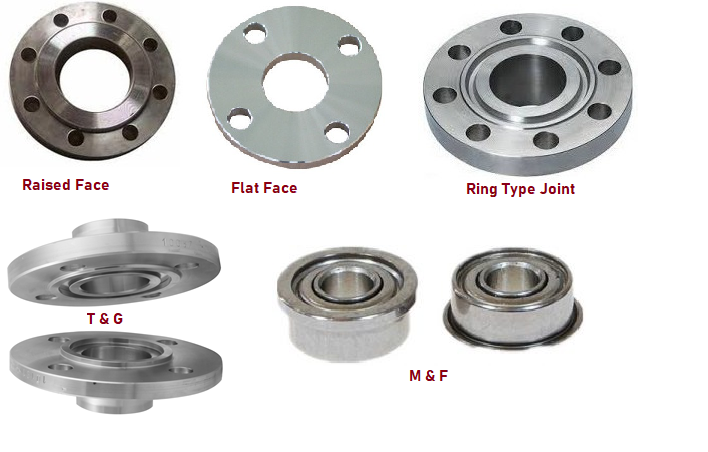
Raised Face (RF)
Raised face flanges are the most common type used in process plant applications and are easily identifiable. It is called a raised face because the sealing face is higher than the circular face of the bolt. This face type enables a wide range of gasket design combinations such as flat ring sheet type, spiral wound type, double wall type, and other metal composite materials.
The purpose of the RF flange is to concentrate more pressure in a smaller sealing area, thereby increasing the joint’s ability to hold pressure. Diameter and height are defined in ASME B16.5 by pressure class and diameter. The pressure level on the flange determines the height of the sealing strip. The typical flange face finish for ASME B16.5 RF flanges is 125 to 250 µin Ra (3 to 6 µm Ra). For pressure classes 150 and 300, the sealing strip height is approximately 1.6 mm (1/16 inch). For pressure classes 400, 600, 900, 1500, and 2500, the sealing strip height is approximately 6.4 mm (1/4 inch).
Flat Face (FF)
A flat face flange has a sealing surface in the same plane as the circumferential surface of the bolt. Flat face flanges should not be bolted to raised face flanges. A soft type (non-metallic) full-face gasket is generally used between two flat-face flanges while making a joint connection. This type of flange face is also known as a plain face. Flat-face flanges are preferred for low-pressure applications. Flat-face flanges are not suggested to mate with an RF flange.
Ring Joint Flange (RTJ)
Ring-type connection flanges are typically used in high-pressure (class 600 and above) and/or high-temperature applications above 800°F (427°C). They have grooves cut into the faces that are steel ring gaskets. As the tightened bolts force the gasket between the flanges into the groove, the flanges seal, deforming the gasket to seal it in the groove, creating a metal-to-metal seal.
The RTJ flange has a raised face with a machined annular groove. This raised surface does not act as part of the sealant. In the case of O-ring sealing RTJ flanges, the raised faces of the flanges that are mated and clamped together may come into contact. In this case, the compressed gasket does not carry any additional load beyond the tension of the bolt, and vibration or movement will not further crush the gasket and reduce the stress in the joint.
RTJ flanges can be sealed with RTJ gaskets in various styles (R, RX, BX) and profiles (e.g. R-style Octagonal/Oval). The most common RTJ gasket is R; styled with an octagonal cross-section to ensure a very strong seal. The “shallow groove” design accepts octagonal or oval cross-section RTJ gaskets.
Lap Joint Flange
The lap flange has a flat side that is not used to seal the flange joint but simply accommodates the back of the stub end. The sealing surface is actually at the stub end itself and can be either flat or raised.
Male and Female Flange
Male and female flanges require adjustment of the flange. The flange face has an area beyond the normal (male) flange face. The other flange or mating flange has a matching recess (female) machined into the face.
The female face is 3/16″ deep and the male face is 1/4″ high, both with a smooth finish. The outer diameter of the female face is used to locate and hold the gasket. Basically, two versions are available; a small M&F flange and a large M&F flange. Custom male and female shrouds are often found on heat exchanger shells to channel and cover the flanges.
Fig. 1: Various Flange Faces
Tongue and Groove Flange
The tongue and groove surfaces of these flanges must match. One flange face has a raised ring (Tongue) machined into the flange face and the mating flange has a matching recess (groove) machined into that face.
Tongue and groove facings are standardized in both large and small. they. They differ from male and female threads in that the inner diameter of the tongue and groove does not protrude into the flange base, thus retaining the seal at its inner and outer diameters. These are commonly found on pump covers and cam covers.
Tong and groove joints also have the advantage of being self-aligning and acting as a reservoir for glue. Blade joints keep the load axis aligned with the joint and do not require extensive machining.
Common flange faces such as RTJ, T&G, and F&M should not be bolted. The reason for this is that the contact surfaces do not match and there are no seals that have one type on one side and another type on the other.
Flange Face Finishes
To ensure that a flange mates with the gasket and the companion flange perfectly, ASME B16.5 requires some roughness on the flange surface area for RF and FF flange finish. The type of roughness defines the type of flange face finish for the flange face surface.
Common types of flange face finishes are
stock,
concentric serrated,
spiral serrated,
smooth flange finish, and
cold water finish.
Steel flanges are available with four basic face finishes, however, the common objective of any type of flange face finish is to create the desired roughness on the flange face. It ensures a strong match between the flange, the gasket, and the mating flange for a high-quality seal.
Let’s now learn the most common flange face finish types:
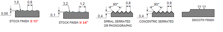
Stock Finish
The most widespread type of flange finish is Stock finish. It suits a large majority of applications. The compressive pressure embeds the soft gasket face into the flange finish resulting in a good seal formation due to the high friction between the contacting faces.
Bolting of the mating flanges squeezes the gasket into the flange face surface and creates a very tight seal.
A stock finish face is produced using a phonographic spiral groove having a 1.6 mm radius round-nose tool with a depth of 0.15 mm and a feed rate of 0.8 mm per revolution. The resulting surface “Ra” values (AARH) range from 125 µinch to 500 µinch (125 µm to 12.5 µm).
Spiral Serrated Finish
Spiral Serrated Surface is a phonographic spiral groove type that differs from the stock surface. The grooves are made with a 90-degree tool (not a round nose tool) that creates a “V” shape with a 45-degree serration angle. The serrated surface is concentric or helical with 30-55 grooves per inch and a roughness of 125-250 microinches.
Concentric Serrated Finish
The grooves are machined using the same 90-degree tooling used for the spiral splines, but the splines have a uniform design on the face of the flange. To create concentric grooves, the tool feed rate is 0.039 mm per revolution and the depth is 0.079 mm.
Smooth Finish
Flanges with a smooth finish will not show any grooves to the bare eye. Tool marks are not visible to the naked eye. Metal-facing gaskets such as the jacketed type make use of this type of flange finish. This flange finish is achieved by machining the contact surface with a continuous spiral groove machined to a depth of 0.05mm with a 0.8mm radius round nose tool at a feed rate of 0.3mm per revolution.
Fig. 2: Flange Face Finishes
Cold Water Finish
The appearance of the cold water finish is smooth and shiny. The normal range of AARH values for these types of flange surfaces is between 85 µinch to 100 µinch. Metal-to-metal sealing without the use of a gasket requires this type of flange finish.
Definition of AARH
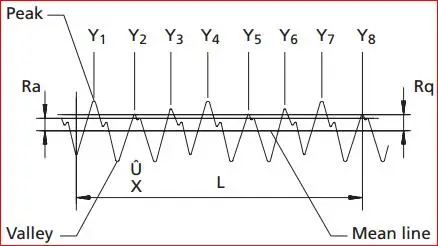
The full form of AARH for flange face finishes is arithmetic average roughness height. AARH refers to the flange face’s smoothness/roughness. The AARH values are very important during the flange and gasket material selection process. Higher AARH or “Ra” values signify a more rough surface and vice versa. Specific surface roughness is deliberately generated for specific applications.
The “Arithmetic Average Roughness Height” of AARH is the common indicator for measuring surface roughness. The AARH is defined as the average height of the irregularities on the metal surface, from the mean line. The AARH is measured in micro-inches and denoted by the symbol “Ra”.
Depending on the type of application, there are various standards governing the roughness of surfaces. The name of the equipment used to measure the surface roughness is “profilometer”.
Flange AARH
As the flange face finish plays an important role in the gasket’s reliability and service life, ASME/ANSI defined specific roughness standards for the flanges. According to those standards, the serrated, spiral serrated, and concentric flange face finish should have an average roughness of 125 µinch to 250 µinch (3.2 µm to 6.3 µm).
Fig. 3: AARH
Specially designed tools with a radius of 0.06 inches (1.5mm) or larger are used to imprint a rough finish on the flange. The groove density on the flange face is usually from 45 grooves per inch to 55 grooves per inch (1.8 grooves/ mm. to 2.2 grooves/ mm.).
When the average flange face roughness is not according to the described standards, the sealing of contacting surfaces would not be properly leading to possible leakage.
Allowed AARH Imperfections
The parameters that govern the sealing performance of the flanges’ gaskets are
AARH,
the flange dimensions, and
the pressure of the stud bolts.
As per the ASME, the adjacent imperfections must be separated by a distance of at least 4 times the maximum radial projection. The radial projection is calculated by subtracting the inner radius from the outer radius.
Note that, the serrations are marked at the same level, and any protrusion above them is not acceptable. These may cause the adjacent serrations to lose hold of the gasket material and may result in wear and leakages.