Recent Posts

What is a Slurry Pump? Selection and Types of Slurry Pumps

As the slurry is highly abrasive, thick, corrosive, and contains a high concentration of solids, it is very challenging to move it. For pumps also, it is very tough. But with a proper selection of slurry pumps, the operation can be smooth for long-term performance. In this article, we will discuss the basics of slurry pumps, their working, types, and selection.

What are Slurry Pumps?

Slurry pumps are heavy-duty and robust pumps (majorly centrifugal) that are capable of handling tough and abrasive fluids like slurries.

Some examples of industries that handle slurries are mining, dredging, steel processing, foundries, power generation, drilling mud, pulp and paper, wastewater treatment, mineral processing, etc. Due to the presence of solid particles and their highly thick and viscous nature, slurry movement requires more power than normal fluids. So, specially designed heavy-duty pumps are required to work as slurry pumps.

Selection of Slurry Pumps

There are various types of pumps that can pump slurries. However, the selection of exact slurry pumps depends on some critical considerations as listed below:

  • Type of Slurry to be handled including the size and nature of the solid particles present.
  • Corrosive property of the slurry mainly to decide pump material for the service.
  • Pipe size – the pipe ID must be considerably bigger than the maximum particle size.
  • Static head requirements; and
  • Available NPSH
  • Length of slurry pipe or pipeline
  • Pump operating parameters specifically discharge pressure and speed, the lower the better.
  • Cost

Slurry Pump Components

There are six basic components in a slurry pump. They are:

  • Impeller: Two options to choose from, closed impeller or open impeller.
  • Shell: Two options to select from; Solid single-piece or split shells.
  • Drive Control: Three types of drive control; Belt drive, gearbox drive, or direct connection of the motor with the shaft.
  • Suction plate liner
  • Shaft seals: Three design options; Stuffing box, mechanical seal, or expeller.
  • Bearing Assembly

Types of Slurry Pumps

Based on the working methodology, there are two types of pumps that are used to handle slurries.

  • Centrifugal slurry pump and
  • Positive displacement slurry pump

Centrifugal Slurry Pumps

The most common type of slurry pump is the centrifugal pump with a larger impeller, thicker vanes, and more horsepower. The working of the centrifugal slurry pump is quite simple. They use the centrifugal force generated by a rotating impeller which pushes the slurry to move through the discharge.

When choosing a centrifugal slurry pump the following should be decided:

  • To minimize the wear of the impeller, a recessed type large and thick open impeller can be used. Closed impellers should be avoided.
  • Metal casing with proper thickness and rubber lining to be considered.
  • Cavitation issues.

Positive Displacement Slurry Pumps

When a low slurry flow rate with improved flow control and greater efficiency is desired, a positive displacement slurry pump is more suitable. Common positive displacement pumps used for slurry service are

  • Rotary lobe pumps
  • Screw pumps
  • Diaphragm pump
  • Peristaltic pumps
  • Gear pumps, and
  • Progressive cavity pumps

Click here to learn the main differences between centrifugal and positive displacement pumps

Again, depending on the installation of the slurry pumps, they are categorized as follows:

  • Horizontal slurry pumps
  • Vertical slurry pumps
  • Submersible slurry pumps.

Horizontal Slurry Pumps

Horizontal slurry pumps have their hydraulic end and the drive unit is located outside the sump. This group of slurry pumps is manufactured for a wide range of head, flow conditions, and material options. Horizontal slurry pumps usually use standardized electrical motors and seals. They are not suitable for plants where there is a risk of flooding.

Vertical Slurry Pumps

There are two types of vertical slurry pumps:

  • Tank pumps
  • Cantilever/sump pumps

Tank pumps are dry-installed pumps. The sump is incorporated into the pump. Their open sump and vertical inlet prevent air blocking, which provides a smooth operation. They don’t have submerged bearings or shaft seals, but quite a long shaft overhang from the lower bearing to the impeller.

Cantilever/sump pumps are considered semi-dry installed, as the hydraulic end is lowered into the slurry, but the drive unit and support structure are dry installed. There are no submerged bearings or shaft seals similar to tank pumps, but they have a long shaft overhang.

Submersible Slurry Pumps

Submersible slurry pumps are usually positioned at the bottom of a tank, pond, or lagoon. The slurry materials are taken in at the pump suction and passed through a hose connected to the discharge valve.

Submersible pumps provide a lot of benefits as listed below:

  • As they directly operate in the slurry, they do not need an additional support structure. Hence, submersible slurry pumps occupy less space.
  • The motor and volute of submersible slurry pumps are integrated into a single unit. Hence, they are compact and easy to install.
  • As they operate underwater, they generate low noise and so silent operation.
  • The surrounding fluid cools the motor which results in smaller and more efficient sumps.
  • Several installation modes, all of which are either portable or semi-permanent. So, they are enough flexible.

There are other types of classification of slurry pumps as well like Self-priming slurry pumps and flooded suction slurry pumps.

Self-Priming slurry pumps operate from land. A hose is connected to the pump’s intake valve through which the pump draws the slurry to discharge the material.

The flooded suction slurry pump is connected to a tank or hopper. It uses gravity force to move slurry and liquid from the enclosure. They are placed at the bottom or below the water and use the gravity force to continuously fill the pump and then pass the material out through the discharge valve.

Slurry Pump Installations

Depending on the environmental condition, there are three types of slurry pump installations:

  • Wet Environment– This type of slurry pump installation involves submerging the product fully for underwater operations.
  • Dry Environment– In a dry environment, the pump drives and bearings are kept away from the abrasive slurry. It calls for a horizontal pump as the shell, impeller, suction liner, and shaft sleeve have to be on the wet side.
  • Semi-Dry Environment– Since it’s an unusual scenario, a special type of horizontal slurry pump installation is preferred.

What Is White Rust? Its Formation, Prevention, and Treatment

Galvanized steel is widely used to protect steel from rust or corrosion. A thin coating of zinc is fused to the steel surface in the galvanization process which prevents the steel from to expose on a corrosive environment. But, that same zinc layer can form its own rust known as white rust. In this article, we will discuss white rust, its formation, and its prevention.

What is White Rust?

White rust is a localized corrosion attack on zinc surfaces and appears as a white, chalky substance as a deposit. This is rapid corrosion and is usually formed when zinc is exposed to oxygen and hydrogen. White rust is also known as white storage stain.

White rust is more predominant on new zinc-coated steel products. This deposit damages the appearance of steel and gradually consumes the complete zinc coating. White rust is basically zinc hydroxide formed due to the chemical reaction of zinc with air and water in wet conditions.

What Causes White Rust?

White rust appears on a freshly galvanized steel material when it is put into service in contact with water, or hydrogen dioxide. During these initial days, the zinc layer is the most prone to white rust on steel attacks.

However, older zinc surfaces can also be corroded by white rust when the surfaces are exposed to high pH, very high conductivity water, or when the old surfaces are aggressively cleaned.

When galvanized steel is stored for future use, moisture (rain, dew, condensation) can easily be trapped between individual items without adequate air circulation which may lead to the formation of white rust. So, basically, the following factors contribute the most to the formation of white rust:

  • Climate (Wet)
  • Air Circulation (Poor Ventilation)
  • Storage method and Place (Tightly packed storing where moisture can trap and stay for extended periods)

Is White Rust Bad?

The formation of white rust highly damages the appearance. Also, sometimes they make the coating useless and the base product (Steel) again becomes prone to corrosion attack. So, white rust is not desirable and must be controlled or eliminated.

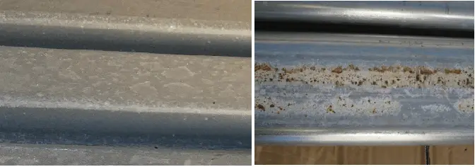
Typical White Rust on Galvanized Steel
Fig. 1: Typical White Rust on Galvanized Steel

Prevention of White Rust

There are several ways that can be followed to prevent the formation of white rust. Some of those methods are:

  • Allowing the zinc to form stable oxides prior to exposure to moisture.
  • Avoid exposure to water (Outside products must be covered with a ventilated waterproof covering)
  • Eliminate the possibility of condensation (Water repellent or barrier coatings can be provided)
  • Using passivating chemicals or oils to prevent the oxidation of the zinc.
  • Store galvanized steel products in a well-ventilated dry location.
  • Avoid exposing the cold zinc material to a warm environment

Repairing White Rust/ White Rust Treatment

There are certain industry-standard treatment methods that can be followed to repair galvanized steel from white rust. The treatment procedures depend on the severity of the white rust damage.

Light White Rusting: When a light film of white powdery residue of white rust is formed on the product surface, it can easily be removed by a stiff nylon brush. When brushing alone is insignificant, a mixture of mineral oil and sawdust can be used on the surface.

Moderate White rusting: When the stain is moderate, it can be removed by washing with a 10% (by volume) acetic acid solution and then thoroughly rinsing with water to neutralize the surface. Stiff brush nylon can be used. Before restacking the sheets need to be made completely dry.

Severe White Rusting: For severe white rusting, the zinc hydroxide corrosion can be dissolved using weak acidic solutions like vinegar. A solution of 5% (by volume) of phosphoric acid in water along with a wetting agent can also be effective. After cleaning, the products need to be immediately well-rinsed and then thoroughly dried.

A coating thickness check needs to be performed to decide the extent of the galvanized coating damage to understand if the same product can be put into service or need reinstatement of the coating.

What is a Fire Pump? Working, Sizing, and Types of Fire Pumps

Fire pumps are one of the essential components of most water-based fire protection systems, especially for high-rise taller buildings and structures. Their main job is to increase the water pressure when the water source does not have adequate pressure to supply the system. In this article, we will discuss the working and types of fire water pumps.

Working Principle of a Fire Water Pump

A fire water pump consists of a driver and a controller. Each pump works in any one of the following two working principles:

Centrifugal-type fire water pumps generate centrifugal forces by rotating their impeller and throwing the water from the center of the impeller to the outer parts of the impeller. On the other hand, positive displacement type fire water pumps take a selected amount of liquid as input and use mechanical action to displace that through the outlet. In general, they use pistons, gears, vanes, lubes, etc to increase the liquid pressure while discharging.

Centrifugal fire water pumps are used for high flow rates to provide a constant water flow mainly for buildings, utility stations, etc. Positive displacement-type fire water pumps are best suited for non-water services, specifically for foam concentrate or water mist systems.

A fire pump in a fire sprinkler system normally receives water from either an underground water supply or a water tank, lake, or reservoir. These pumps are is powered by electricity or diesel fuel. The high pressure supplied by the fire pumps helps in the proper distribution of water through the sprinkler system and hose standpipes.

Types of Firewater Pumps

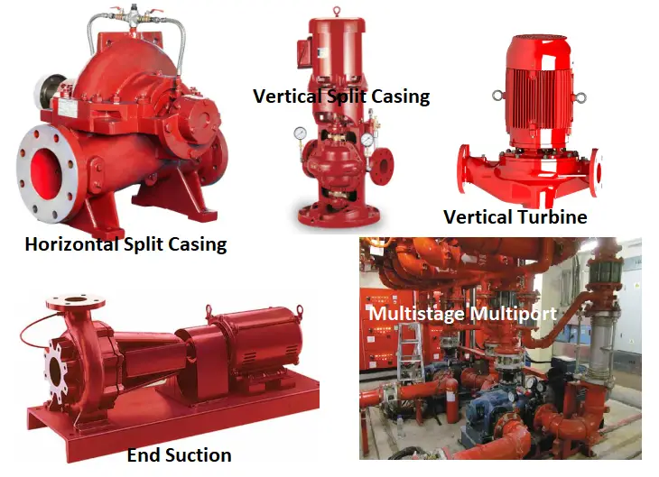
Depending on the working philosophy mentioned above there are two main types of fire water pumps; Centrifugal and Positive displacement. All these fire pumps can again be sub-divided into various types as listed below:

  • Centrifugal Fire Water Pump
    • Horizontal and Vertical Split-Case Pump
    • Vertical Turbine Pump
    • In-Line Pump
    • End Suction Pump
    • Multistage Multiport Pump
  • Positive Displacement Fire Water Pumps

Centrifugal Fire Water Pumps

Centrifugal fire pumps are the most widely used fire pumps. They can handle a large volume of water. The common sub-types of centrifugal fire pumps are discussed below:

Horizontal and Vertical Split-Case Pumps

Horizontal Split case pumps are very reliable fire pumps with long lifespans and size availability. They are available in a wide range of rated flow and pressure capacities and are thus suitable for a range of fire-water applications. In a horizontal split-case pump, the flow is divided and enters the impeller from opposite sides of the pump housing. The pump has a split casing (and hence the name) that is easy to open during pump maintenance. The pump is connected to the driver by a horizontal shaft.

A Vertical split casing pump is almost similar to that of a Horizontal split casing pump. But the orientation of the pump and motor are vertical. The vertical motor placement consumes less floor space and the
motor is protected against potential flooding conditions. Both horizontal and vertical split case pumps require a water source providing a positive suction pressure.

Types of Fire Pumps
Fig. 1: Types of Fire Pumps

Vertical Turbine Pumps

The fire protection pump standard NFPA 20 allows vertical turbine pumps for fire water systems. They have the ability to start with negative pressure and can take water input from a below-grade source. They are available in a range of pressures and capacities and have diesel or electric drivers.

This type of fire pump is available as oil-lubricated enclosed-line-shaft and water-lubricated open-line-shaft pumps. Both vertical turbine pump types are designed for installation in drilled wells, lakes, streams, open swamps, and other subsurface sources.

In-Line Pumps

When there is limited space, in-line pumps are widely used. They can have both vertical and horizontal shafts, but the vertical shaft is the most common. Vertical in-line fire pumps provide a smooth flow of water throughout the system. This type of fire pump has a very low initial cost but they are expensive to repair. Their capacity is limited and only used with an electric driver.

End Suction Top Discharge Pump

An end suction fire pump has its discharge perpendicular to the suction inlet. They are compact and need less space as compared to horizontal split case fire pumps but have a limited capacity. End suction fire pumps are available with either an electric driver or a diesel driver.

Multistage Multiport Pump

Multistage Multiport fire pumps have multiple impellers in series in a single casing driven by a horizontal shaft. The casing has multiple discharge outlets that deliver fluids at different pressures. There is an increase in pressure in each consecutive series impeller. They can be run by an electric motor or a diesel engine.

There are certain benefits of using a multiport fire pump as listed below:

  • The number of pumps required will reduce.
  • Comparatively less pipe work and fewer valves.
  • Reduced structural loads and associated costs as only one pump may be required
  • Due to less electricity or fuel to drive only one pump energy is saved.
  • Pollution is also reduced.

Positive Displacement Fire Pumps

As compared to centrifugal fire pumps, positive displacement fire pumps generate very high pressures but they have limited flow volume. They come in two main types, reciprocating and rotary. The use of positive displacement fire pumps is not common and is limited only to specialized applications with water mist and foam-water systems.

Fire Pump Drivers

As outlined in NFPA 20, there are three types of drivers to drive the impeller and shafts of a fire pump. They are:

  • Electrical motor,
  • Diesel engine, and
  • Steam turbine systems.

The most common type of driver is the electrical motor. Electrical motor drives are cost-effective and easy to operate. The motor takes electrical power to spin which spins the shaft connected to the impeller.

While a power source is not continuously available, the diesel engine is a good choice. The diesel motor is mounted on the same skid as the pump. Diesel engines use the power generated due to the combustion of fuel to turn the impeller. However, diesel engines need a lot of infrastructure and maintenance and a governor system to control the power.

Steam turbines as fire pump drivers are very rarely used. Steam turbines need a separate unit to generate steam and costly equipment like a boiler, steam generator, etc.

Sizing a Fire Pump

A fire pump must be designed properly to handle the most demanding fire sprinkler system. Incorrectly sized fire pumps can result in several problems like:

  • Improper system function.
  • Undeveloped spray patterns from sprinklers.
  • Insufficient pressure to hose valves.
  • Too much pressure, causing components to burst and break open while operating.

Hence, the first step of fire pump sizing is to identify the most demanding system. The standpipe is the most demanding system in most commercial buildings. The standpipe system design and the fire pump flow rate requirements are given in NFPA 14.

Next, the required pressure must be calculated. Pressure requirement can be calculated as (Demand at the top + static losses+ pipe friction losses – source water pressure). Other requirements are the size of the room where the fire pump will be installed.

If the sprinkler load is the most demanding then the fire pump must be designed based on the hydraulic demand of the sprinkler system.

Once the above parameters are known, a fire pump can be selected. NFPA Fire Protection Handbook provides enough guidelines for selecting the required fire pump.

Characteristics of a Fire Pump

The main characteristic feature that a fire pump should have are listed below:

  • Pump internals must be made from non-corrosive materials.
  • The pump selection must be based on the required NPSH value, flow, and head demand to avoid cavitation.
  • All fire pumps must have adequate power reserves.

Detailed Online Course on Pipe Stress Analysis (25 hours of Content) with Certificate + Free Trial Version of Pipe Stress Analysis Software

This course is created by an experienced pipe stress analysis software developer (15+ years experience), Ph.D. and covers all features of onshore above ground and underground piping and pipeline analysis. This course is based on the PASS/START-PROF software application, though it will be interesting for users of any other pipe stress analysis software tools as it contains a lot of theoretical information.

The course consists of video lectures, quizzes, examples, and handout materials.

Type: an on-demand online course.

Duration: 25 hours.

Course price: 200 USD 30 USD.

Instructor: Alex Matveev, head of PASS/START-PROF Pipe Stress Analysis Software development team. Always available for your questions at Udemy, LinkedIn, Facebook

Alex Matveev

Who should attend

All process, piping, and mechanical engineers specialized in design and piping stress analysis for the specified industries:

  • Oil & Gas (Offshore/Onshore)
  • Chemical & Petrochemical
  • Power (Nuclear/ Non-Nuclear)
  • District Heating/Cooling
  • Water treatment
  • Metal industry

Training software

All trainees are provided with a free 30-day pipe stress analysis software license (PASS/START-PROF). How to get a free license

Certificate

After finishing the course, you will receive Certificates from both the Udemy and from PASS Team.

Detailed Training Agenda: Download the detailed training agenda in PDF.

Brief Summary of the Course

Introduction
Section 1. Working with PASS/START-PROF User Interface339 min
Section 2. Piping Supports138 min
Section 3. Stress Analysis Theory and Results Evaluation237 min
Section 4. Underground Pipe Modeling249 min
Section 5. Static and Rotating Equipment Modeling and Evaluation244 min
Section 6. Expansion Joints, Flexible Hoses, Couplings106 min
Section 7. Non-Metallic Piping Stress Analysis99 min
Section 8. External Interfaces65 min
Brief Course Summary

How to Enroll for the Course

Visit the Pipe Stress Analysis course page on Udemy

Then click Add to Cart or Buy Now and follow the instructions

What you will learn in this Course

  • Pipe stress analysis theory. Load types. Stress types. Bourdon effect. Creep effect in high-temperature piping, creep rupture usage factor (Appendix V B31.3)
  • ASME B31.1, ASME B31.3, ASME B31.4, ASME B31.5, ASME B31.8, ASME B31.9, ASME B31.12 code requirements for pipe stress analysis
  • How to use PASS/START-PROF software for pipe stress analysis
  • How to work with different load cases
  • How to model different types of piping supports, the spring selection
  • What are stress intensification and flexibility factors and how to calculate them using FEA and code requirements
  • How to model trunnion and lateral tees
  • How to model pressure vessels and columns connection: modeling local and global flexibility, WRC 297, WRC 537, FEA
  • How to model storage tank connection (API 650)
  • How to model connection to air-cooled heat exchanger API 661, fired heater API 560, API 530
  • How to model connection to Pump, Compressor, Turbine (API 610, API 617, NEMA SM23)
  • How to model buried pipelines: Submerged Pipelines, Long Radius Bends Modeling of Laying, Lifting, Subsidence, Frost Heaving, Fault Crossing, Landslide
  • Underground pipelines Seismic Wave Propagation, Pipe Buckling, Upheaval Buckling, Modeling of Pipe in Chamber, in Casing with Spacers. Electrical Insulation kit
  • Minimum design metal temperature calculation MDMT calculation, impact test
  • Modeling of Expansion Joints, Flexible Hoses, Couplings
  • Import and export to various software: CAESAR II, AVEVA, REVIT, PCF format, etc.
  • How to do Normal Modes Analysis and how to interpret results
  • ASME B31G Remaining Strength of Corroded Pipeline Calculation

Types of Lines in Engineering/ Technical Drawings and Their Uses

Lines play an important role in the technical and engineering industry. Explaining a complex drawing in words is impossible and hence, engineering drawing has become the worldwide language of engineers, designers, technicians, scientists, and craftsmen. The shape, scale, and interrelation of a complex thing can easily be transmitted using engineering drawings. Every engineering drawing has various types of lines in it and so, lines are a major part of the graphic language.

Lines used in any engineering drawing may be straight or curved. Lines are defined as elements with no breadth but unlimited length (magnitude). Lines locate two points that are not in the same location but fall along the line. A straight line denotes the shortest distance between two points.

Lines can be drawn in any direction. Straight and curved lines are parallel when the shortest distance between them remains constant.

Again, lines are differentiated as thick lines (0.6 mm thickness), thin lines (0.3 mm thick), Continuous lines, dashed lines, freehand lines, zigzag lines, chain lines, etc. In this article, we will learn the various types of lines that are widely used in engineering drawings.

Types of Lines for Engineering and Technical Drawings

There are 12 main types of lines usually used in engineering drawing while drafting. They are:

  • Visible lines
  • Hidden lines
  • Section lines
  • Center lines
  • Dimension lines
  • Extension lines
  • Leader lines
  • Cutting plane lines
  • Break lines
  • Phantom lines
  • Borderlines
  • Arrowheads

Visible Lines

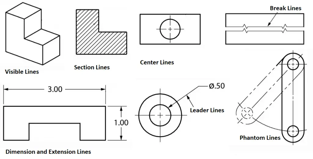
They are dark and thick lines of any engineering design drawing. Also known as object lines, visible lines define the features that will be clearly visible in a particular view. They define the outline or contour of the object. All thick lines are usually drawn 0.6 mm thick. Refer to Fig. 1 which gives an example of various types of lines used in technical and engineering drawing.

Uses: Visible lines represent the visible edges and outlines of objects.

Hidden Lines

Hidden lines are light, dashed, narrow, and short. They provide features that can not be seen in a particular view but are provided to clarify some specific features. To start and end hidden lines, a dash is always used except when a hidden line starts or ends at a parallel visible or hidden line. Dashes should meet in the corners. All thin lines are of 0.3 mm thickness. Sometimes hidden lines can be omitted.

Uses: Hidden lines represent edges or boundaries that are not visible from the current view, such as hidden features inside an object.

Types of Lines in Engineering Drawing
Fig. 1: Examples of Types of Lines in Engineering Drawing

Section Lines

Section lines are thin lines drawn at a 45-degree angle. They are also called hatch lines. In any sectional view, section lines indicate the material that has been cut through.

Uses: It represents the surface that has been cut in a sectional view, typically shown as hatching.

Center Lines

Center lines in an engineering drawing show the center of a round or cylindrical shape. The line is drawn using a thin line with alternating long and short dashes. Long dashes are used to begin and terminate center lines. This is also sometimes known as long/short-dashed thin lines.

At the center point, the center lines must intersect by crossing either the long or short dashes. They should continue a short distance beyond the object or feature. To represent that two or more features are in the same plane, center lines can be joined within a single view. The center lines are not meant to cross the space between views.

Uses: A center line Indicates the center of circles, arcs, or symmetrical parts. Represented by a long dash followed by a short dash.

Dimension Lines

As the name suggests, dimension lines represent the dimensions or sizes of components in an engineering drawing. They are represented by thin lines with arrowheads at the ends that are broken along their length to make room for the dimension number. The dimension (length) is mentioned clearly. Refer to Fig. 2 which shows typical dimension lines used in Engineering Drawings.

Extension Lines

Extension lines which are added using thin lines determine the extent of a dimension. Sometimes, extension lines are used to demonstrate the extension of a surface to a theoretical intersection.

Leader Lines

Leader lines are used to mention a specific note to a feature on a drawing, as well as to direct dimensions, symbols, item numbers, and part numbers. they are added using thin lines.
The main features of leader lines are:

  • Usually drawn at 30, 45, and 60 degrees.
  • It has a short shoulder at one end that begins at the center of the vertical height of the text and a standard dimension arrowhead at the other end that touches the feature.
  • Leader lines should not cross one another and should not be overly long.
  • Leader lines are not drawn in vertical or horizontal orientation.
  • Dimension lines, section lines, and extension lines should not be parallel to leader lines.

Uses: Connects a note, dimension, or reference to a specific feature on the drawing.

Cutting Plane Lines

Cutting plane lines are thick broken intermittent lines with small 90-degree arrowheads. These type of lines indicates when a section is mentally cut in half to better perceive the internal detail. These types of lines are also sometimes known as viewing plane lines.

Uses: It shows where a sectional view is taken.

Various Types of Lines used in Technical Drawings
Fig. 2: Various Types of Lines Used in Technical Drawings

Break Lines

Break Lines in engineering drawings are very important and are used to separate sections for clarity or to shorten a section. There are three types of break lines, each with a distinct line weight:

  • Short Break Lines: Short break lines are denoted by a thick wavy line and are used to break the edge or surface of a part to reveal a concealed surface.
  • Long Break Lines: Long, thin lines are used as long break lines to indicate that the center section of an object has been removed so that it can be drawn on a smaller piece of paper.
  • Cylindrical Break Lines: To depict spherical parts that have been broken in half to better clarify the print or to shorten the object’s length, thin lines are used as cylindrical break lines.

Uses: They are used to show that a portion of an object has been removed or that the object continues beyond the current view.

Phantom Lines

Phantom Lines are thin lines composed of long dashes alternated with pairs of small dashes. This type of line in engineering drawings serves the following purposes:

  • They depict the alternate location of moving parts.
  • They demonstrate the relationship between elements that fit together.
  • They demonstrate repetitive detail.

Uses: Indicates alternate positions of moving parts, adjacent positions, or repeated details.

Border Lines

Thick and continuous lines that show the drawing’s boundaries or divide different objects drawn on the same sheet are known as border lines. They are also used to distinguish the title block from the body of the illustration.

There are some other types of technical drawings as listed below:

Symmetry Lines:

  • Symmetry lines are imaginary lines that are believed to pass through the centers of areas, shapes, objects, and drawn structures. The symmetry lines divide the object into equal and similar-looking parts means the object has symmetry with respect to the symmetry line.
  • Uses: Indicates that a drawing or object is symmetrical about a particular axis.
  • Significance: Symmetry lines are important for ensuring that symmetrical parts are correctly represented and that features are mirrored accurately across the axis. This is particularly useful in mechanical and architectural designs where symmetry is a key aspect.

Chain Lines:

  • Chain lines are broken or spaced parallel lines used to indicate pitch lines (which show the pitch of gear or sprocket teeth), center lines, developed views, or features in front of a cutting plane. Typically, chain lines are placed at the beginning and end of long dashes, at center points for center lines, in dimensioning, or for other specific purposes.
  • Uses: Used to indicate pitch lines (for gears or threads), center lines, cutting planes, or paths of motion.

Arrowheads

Arrowheads are used to end dimension lines, leader lines, cutting-plane lines, and viewing plane lines. They are drawn three times the length of the width. Arrowheads can be filled or not filled.

Line Precedence

When two or more lines appear in the same position, the lines that are the least relevant are removed. Lines in engineering drawings are drawn in the following order of precedence/importance:

  • Cutting plane line
  • Visible line
  • Hidden line
  • Centerline

All the above lines are usually predefined in most CAD Software packages as layers. Depending on the layer chosen, the line will be inserted in the drawing and will be visible in a certain way. However, most drafting companies make their own custom layers with different colors to distinguish them from one another.

Types of Lines in Engineering Drawing as per ISO 128-2

The international standard ISO 128 Part 2 provides the basic conventions for lines used in engineering technical drawings. The standard establishes the line types extensively used in engineering drawings for producing diagrams, plans, or maps. ISO 128-2 also provides the designations and configurations of all types of lines, as well as general rules for line draughting.

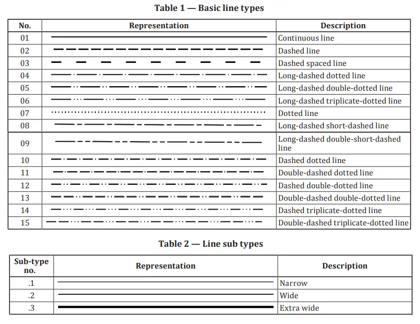
Referring to ISO 128-2, there are 15 basic line types and three line subtypes as represented in the following image (Fig. 3):

Basic Engineering Line Types and Sub-types per ISO 128-2
Fig. 3: Basic Engineering Line Types and Sub-types per ISO 128-2

Technical Line Dimensions:

The width of engineering drawing lines can be one of the following depending on the type and size of the technical drawing.

  • 0.13 mm;
  • 0.18 mm;
  • 0.25 mm;
  • 0.35 mm;
  • 0.5 mm;
  • 0.7 mm;
  • 1.0 mm;
  • 1.4 mm;
  • 2.0 mm.

Note that the line width of any one line must be constant throughout the complete line. If you are a designer and wish to master all the types of lines used in engineering drawing, ISO 128-Part 2 is a must-read for you.

In recent times, due to technological advancement, most of the engineering drawings are produced by CAD software packages. Most of the above-mentioned line types are predefined in CAD Software packages as layers so you don’t have to worry about the uniformity of the line widths. Based on the line requirement of the engineering drawing you can easily choose the necessary layer to display the line in a certain way. Customization of line types is also possible in these CAD software programs.

What is Instrumentation Engineering? Components and Example of Instrumentation

Uhm, is it about music? That’s what people ask us! Every time I tell people my profession, I am asked “What is Instrumentation Engineering?” So let’s get you through it.

By definition, Instrumentation Engineering is a branch that examines the measurement and control of different parameters and the systems associated with them. 

What is Instrumentation?
Fig. 1: What is Instrumentation?

To put it simply, let me say that the perfect example of Instrumentation is our body. One such specific example is how our body regulates temperature.

For us to stay healthy our body temperature must range between 970 F and 990 F. So obviously, someone is constantly monitoring this temperature and maintaining it.

But who is it?

A controller. Its job is to continuously match the measuring value with a set point and then give a corrective output to meet our requirements. In our case, the hypothalamus is the controller here that regulates our body temperature.

Let’s see how.

A hot environment causes the hypothalamus to send signals to the sweat glands, causing you to sweat and cool off. And in the opposite case, when you feel cold, it sends signals to your muscles that create warmth.

Similarly, in any chemical process or power plant, there are a lot of parameters that have to be measured and controlled effectively to obtain the desired results.

As in our body, we have Temperature, BP, Sugar, etc.

In industries, we need to pay attention to the parameters mentioned below to gain effective control and obtain the desired product.

  • Flow
  • Level
  • Pressure
  • Temperature
  • Analyzers

Components of Instrumentation

As the term “Instrumentation” starts with Instruments, Let’s first define it.

An instrument is a device that helps in measuring any of the process parameters. Valves, Thermocouples, Transmitters, Analyzers, etc are typical examples of instruments. These instruments become an essential part of instrumentation and control system design in process and power plants. For monitoring and controlling the system behavior, engineers are dependent on the values displayed in such instruments

There are three main components in any Instrumentation cycle that perform the activity of maintaining and controlling the process parameters effectively are :

  • Sensor
  • Controller
  • Final Control Element

Instrumentation is basically the application of instruments for an experiment, measure, and control of pressure, temperature, flow, density, velocity, force, pH, humidity, or any other process variable of a properly defined system.

Each parameter can be measured through a sensor that is based on different principles and can be selected based on the process application.

Let us first clarify the concept of the sensor.

Sensors are devices that convert physical energy into electrical energy. Sensors are used in our day-to-day life as well eg. Gyser, thermometer, etc.

The most important role of an Instrumentation Engineer is to select the right sensor for the right application. And this depends on many factors like

  1. What is the service of the measuring medium?
  2. What is the desired output?
  3. What is the transmission mode required?
  4. Whether it has to be contact or non-contact type?
  5. What kind of principle best suits our needs?

And much more.

The next step after the sensor comes the transmitter. There’s a very thin line between sensors and transmitters which most people tend to overlook.

As said before, Sensors are devices that convert physical energy into electrical energy. Transmitters are devices that convert the electrical signal into the standard instrumentation signal which is 4-20ma.

Transmitters and sensors usually come in a single assembly that measures and transmits a signal based on its specifications.

The signal from the sensor is sent to a controller system, like PLC/ DCS. These systems are the brain of the process which are fed with formulas to generate desired outputs.

A set point i.e the desired value of a specific parameter is given to this controller. The controller then compares it with the value that is being measured by the sensor.

Based on the difference between the measuring value and the set point, the controller generates a corrective output.

This output is sent to a final control element which takes corrective measures to match the set point given by the user and the value being measured by the sensor.

In a control system, a final control element is a mechanical device that changes a process to match the setpoint and measuring value. Eg, Valves, Dampers, Gates.

This cycle must go on continuously to get the desired product.

Apart from getting the desired output and production levels, what an Instrumentation Engineer needs to look after is the Safety of the Plant.

Not taking proper care of the systems and neglecting the safety norms can lead to an event like Bhopal Gas Tragedy.

Even though everything works in an automated process, it is very important to understand the catastrophic losses if the automated system suddenly stops working.

There have to be enough interlocks, safety alarms, and safety trips included in the system to avoid instrument and human errors.

A HAZOP study – Hazard and Operateblitly Study is performed by a group of professionals including Process Engineers, Instrumentation Engineers, and Safety Engineers to ensure the levels of safety required in a process plant before the designing of the plant is started.

Along with HAZOP, there are different studies like LOPA, Intrinsic Calculations, etc which take place after HAZOP.

This was a brief introduction to what Instrumentation Engineering is. Every topic mentioned here has its own roots and shall be explained in-depth in the upcoming articles.

Example of Instrumentation

Let us try to understand what we read above with an example.

A simple Instrumentation System
Fig. 2: A simple Instrumentation System

Assume that you have a tank whose level has to be maintained in such a way that the water in the tank must not go above 75% of the height of the tank.

Now, as in this picture (Fig. 2), we mounted a level sensor on the top of the tank. This sensor will be calibrated in such a way that it will sense when water reaches the desired set point.

Here the set point is 75% of the tank. As the water reaches the desired set point, it will send a signal to the controller.

The controller will now generate a corrective output and send it to the final control element which is the valve in this case.

As the water is more than the setpoint, the valve will now open and the water in the tank will drain out until it is below 75% of the tank height. This will continue as the water level fluctuates in the tank.

There are many ways to optimize the process below, which we’ll learn in the upcoming articles.

Hence, broadly, Instrumentation engineering is a specialization engineering branch for studying the basics of measuring instruments used in the design and configuration of automated systems in electrical, electronics, and pneumatic domains, etc. The majority of instrumentation engineers work in industries for automation and control of processes. Instrumentation and control systems optimize systems for increased productivity, reliability, safety, and stability. Several devices like microprocessors, microcontrollers, or PLCs are used to measure and control the system parameters.

Thank you for reading! Share your thoughts on this post in the comments section below! Let me know what you’d like to learn more about!

Picture Credits:

  • https://leverageedu.com/blog/electronics-and-instrumentation-engineering/
  • https://www.dataforth.com/tuning-level-control-loops.aspx