Lines play an important role in the technical and engineering industry. Explaining a complex drawing in words is impossible and hence, engineering drawing has become the worldwide language of engineers, designers, technicians, scientists, and craftsmen. The shape, scale, and interrelation of a complex thing can easily be transmitted using engineering drawings. Every engineering drawing has various types of lines in it and so, lines are a major part of the graphic language.
Lines used in any engineering drawing may be straight or curved. Lines are defined as elements with no breadth but unlimited length (magnitude). Lines locate two points that are not in the same location but fall along the line. A straight line denotes the shortest distance between two points.
Lines can be drawn in any direction. Straight and curved lines are parallel when the shortest distance between them remains constant.
Again, lines are differentiated as thick lines (0.6 mm thickness), thin lines (0.3 mm thick), Continuous lines, dashed lines, freehand lines, zigzag lines, chain lines, etc. In this article, we will learn the various types of lines that are widely used in engineering drawings.
Types of Lines for Engineering and Technical Drawings
There are 12 main types of lines usually used in engineering drawing while drafting. They are:
Visible lines
Hidden lines
Section lines
Center lines
Dimension lines
Extension lines
Leader lines
Cutting plane lines
Break lines
Phantom lines
Borderlines
Arrowheads
Visible Lines
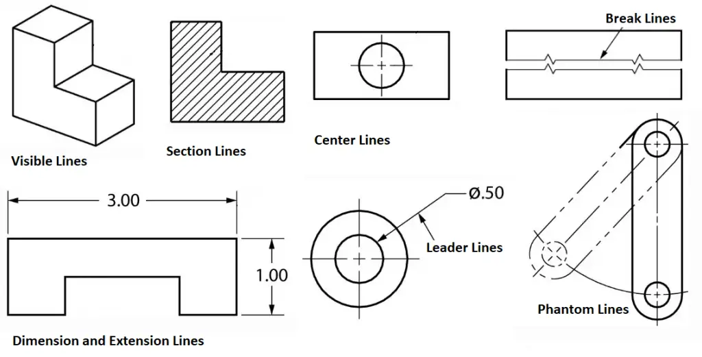
They are dark and thick lines of any engineering design drawing. Also known as object lines, visible lines define the features that will be clearly visible in a particular view. They define the outline or contour of the object. All thick lines are usually drawn 0.6 mm thick. Refer to Fig. 1 which gives an example of various types of lines used in technical and engineering drawing.
Uses: Visible lines represent the visible edges and outlines of objects.
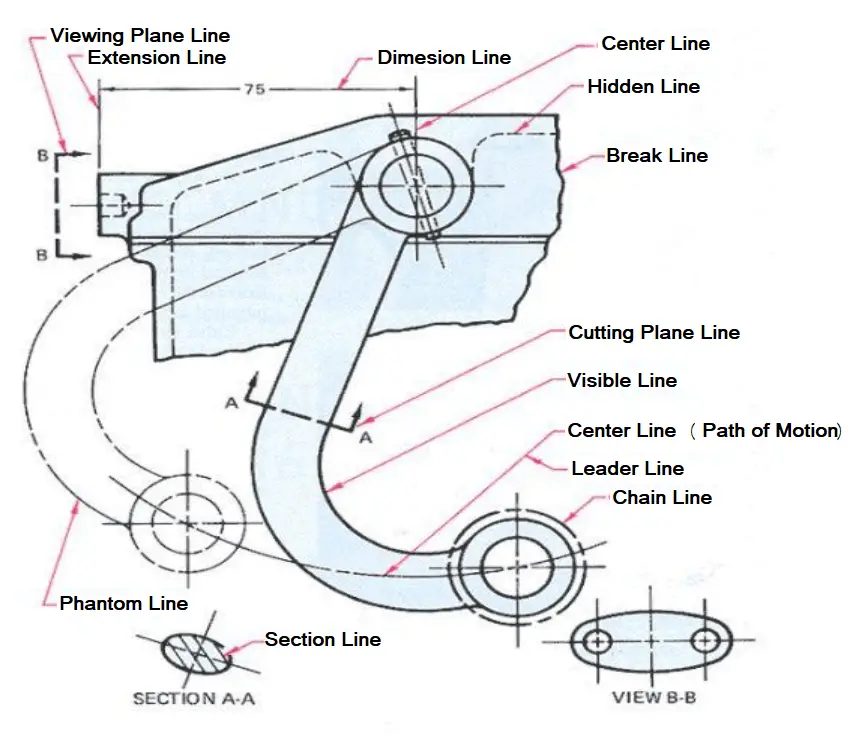
Hidden Lines
Hidden lines are light, dashed, narrow, and short. They provide features that can not be seen in a particular view but are provided to clarify some specific features. To start and end hidden lines, a dash is always used except when a hidden line starts or ends at a parallel visible or hidden line. Dashes should meet in the corners. All thin lines are of 0.3 mm thickness. Sometimes hidden lines can be omitted.
Uses: Hidden lines represent edges or boundaries that are not visible from the current view, such as hidden features inside an object.
Fig. 1: Examples of Types of Lines in Engineering Drawing
Section Lines
Section lines are thin lines drawn at a 45-degree angle. They are also called hatch lines. In any sectional view, section lines indicate the material that has been cut through.
Uses: It represents the surface that has been cut in a sectional view, typically shown as hatching.
Center Lines
Center lines in an engineering drawing show the center of a round or cylindrical shape. The line is drawn using a thin line with alternating long and short dashes. Long dashes are used to begin and terminate center lines. This is also sometimes known as long/short-dashed thin lines.
At the center point, the center lines must intersect by crossing either the long or short dashes. They should continue a short distance beyond the object or feature. To represent that two or more features are in the same plane, center lines can be joined within a single view. The center lines are not meant to cross the space between views.
Uses: A center line Indicates the center of circles, arcs, or symmetrical parts. Represented by a long dash followed by a short dash.
Dimension Lines
As the name suggests, dimension lines represent the dimensions or sizes of components in an engineering drawing. They are represented by thin lines with arrowheads at the ends that are broken along their length to make room for the dimension number. The dimension (length) is mentioned clearly. Refer to Fig. 2 which shows typical dimension lines used in Engineering Drawings.
Extension Lines
Extension lines which are added using thin lines determine the extent of a dimension. Sometimes, extension lines are used to demonstrate the extension of a surface to a theoretical intersection.
Leader Lines
Leader lines are used to mention a specific note to a feature on a drawing, as well as to direct dimensions, symbols, item numbers, and part numbers. they are added using thin lines. The main features of leader lines are:
Usually drawn at 30, 45, and 60 degrees.
It has a short shoulder at one end that begins at the center of the vertical height of the text and a standard dimension arrowhead at the other end that touches the feature.
Leader lines should not cross one another and should not be overly long.
Leader lines are not drawn in vertical or horizontal orientation.
Dimension lines, section lines, and extension lines should not be parallel to leader lines.
Uses: Connects a note, dimension, or reference to a specific feature on the drawing.
Cutting Plane Lines
Cutting plane lines are thick broken intermittent lines with small 90-degree arrowheads. These type of lines indicates when a section is mentally cut in half to better perceive the internal detail. These types of lines are also sometimes known as viewing plane lines.
Uses: It shows where a sectional view is taken.
Fig. 2: Various Types of Lines Used in Technical Drawings
Break Lines
Break Lines in engineering drawings are very important and are used to separate sections for clarity or to shorten a section. There are three types of break lines, each with a distinct line weight:
Short Break Lines: Short break lines are denoted by a thick wavy line and are used to break the edge or surface of a part to reveal a concealed surface.
Long Break Lines: Long, thin lines are used as long break lines to indicate that the center section of an object has been removed so that it can be drawn on a smaller piece of paper.
Cylindrical Break Lines: To depict spherical parts that have been broken in half to better clarify the print or to shorten the object’s length, thin lines are used as cylindrical break lines.
Uses: They are used to show that a portion of an object has been removed or that the object continues beyond the current view.
Phantom Lines
Phantom Lines are thin lines composed of long dashes alternated with pairs of small dashes. This type of line in engineering drawings serves the following purposes:
They depict the alternate location of moving parts.
They demonstrate the relationship between elements that fit together.
They demonstrate repetitive detail.
Uses: Indicates alternate positions of moving parts, adjacent positions, or repeated details.
Border Lines
Thick and continuous lines that show the drawing’s boundaries or divide different objects drawn on the same sheet are known as border lines. They are also used to distinguish the title block from the body of the illustration.
There are some other types of technical drawings as listed below:
Symmetry Lines:
Symmetry lines are imaginary lines that are believed to pass through the centers of areas, shapes, objects, and drawn structures. The symmetry lines divide the object into equal and similar-looking parts means the object has symmetry with respect to the symmetry line.
Uses: Indicates that a drawing or object is symmetrical about a particular axis.
Significance: Symmetry lines are important for ensuring that symmetrical parts are correctly represented and that features are mirrored accurately across the axis. This is particularly useful in mechanical and architectural designs where symmetry is a key aspect.
Chain Lines:
Chain lines are broken or spaced parallel lines used to indicate pitch lines (which show the pitch of gear or sprocket teeth), center lines, developed views, or features in front of a cutting plane. Typically, chain lines are placed at the beginning and end of long dashes, at center points for center lines, in dimensioning, or for other specific purposes.
Uses: Used to indicate pitch lines (for gears or threads), center lines, cutting planes, or paths of motion.
Arrowheads
Arrowheads are used to end dimension lines, leader lines, cutting-plane lines, and viewing plane lines. They are drawn three times the length of the width. Arrowheads can be filled or not filled.
Line Precedence
When two or more lines appear in the same position, the lines that are the least relevant are removed. Lines in engineering drawings are drawn in the following order of precedence/importance:
Cutting plane line
Visible line
Hidden line
Centerline
All the above lines are usually predefined in most CAD Software packages as layers. Depending on the layer chosen, the line will be inserted in the drawing and will be visible in a certain way. However, most drafting companies make their own custom layers with different colors to distinguish them from one another.
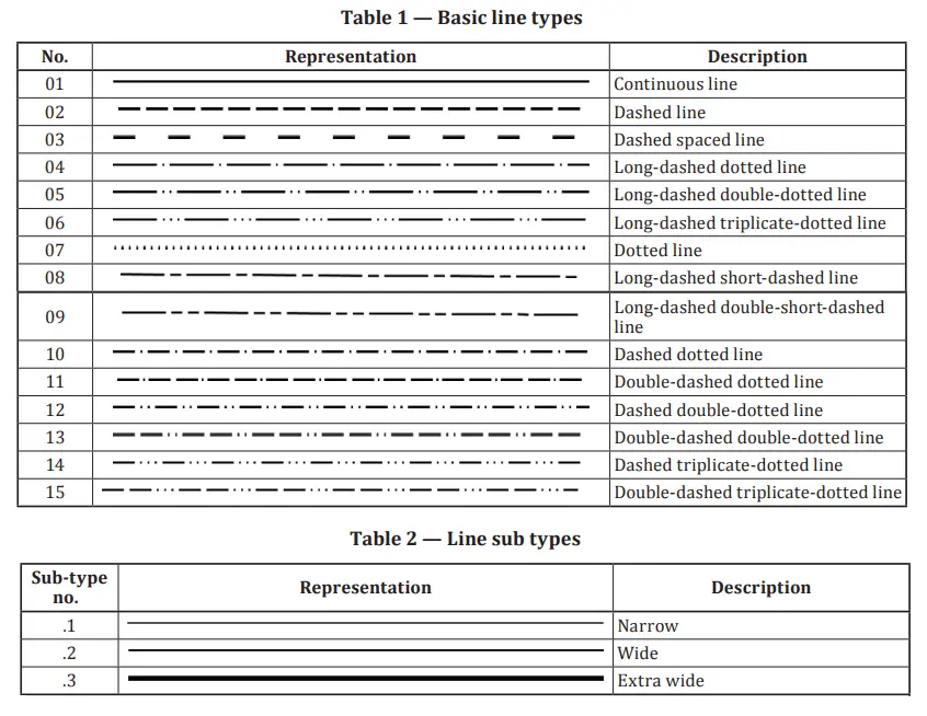
Types of Lines in Engineering Drawing as per ISO 128-2
The international standard ISO 128 Part 2 provides the basic conventions for lines used in engineering technical drawings. The standard establishes the line types extensively used in engineering drawings for producing diagrams, plans, or maps. ISO 128-2 also provides the designations and configurations of all types of lines, as well as general rules for line draughting.
Referring to ISO 128-2, there are 15 basic line types and three line subtypes as represented in the following image (Fig. 3):
Fig. 3: Basic Engineering Line Types and Sub-types per ISO 128-2
Technical Line Dimensions:
The width of engineering drawing lines can be one of the following depending on the type and size of the technical drawing.
0.13 mm;
0.18 mm;
0.25 mm;
0.35 mm;
0.5 mm;
0.7 mm;
1.0 mm;
1.4 mm;
2.0 mm.
Note that the line width of any one line must be constant throughout the complete line. If you are a designer and wish to master all the types of lines used in engineering drawing, ISO 128-Part 2 is a must-read for you.
In recent times, due to technological advancement, most of the engineering drawings are produced by CAD software packages. Most of the above-mentioned line types are predefined in CAD Software packages as layers so you don’t have to worry about the uniformity of the line widths. Based on the line requirement of the engineering drawing you can easily choose the necessary layer to display the line in a certain way. Customization of line types is also possible in these CAD software programs.
What is Instrumentation Engineering? Components and Example of Instrumentation
Uhm, is it about music? That’s what people ask us! Every time I tell people my profession, I am asked “What is Instrumentation Engineering?” So let’s get you through it.
By definition, Instrumentation Engineering is a branch that examines the measurement and control of different parameters and the systems associated with them.
Fig. 1: What is Instrumentation?
To put it simply, let me say that the perfect example of Instrumentation is our body. One such specific example is how our body regulates temperature.
For us to stay healthy our body temperature must range between 970 F and 990 F. So obviously, someone is constantly monitoring this temperature and maintaining it.
But who is it?
A controller. Its job is to continuously match the measuring value with a set point and then give a corrective output to meet our requirements. In our case, the hypothalamus is the controller here that regulates our body temperature.
Let’s see how.
A hot environment causes the hypothalamus to send signals to the sweat glands, causing you to sweat and cool off. And in the opposite case, when you feel cold, it sends signals to your muscles that create warmth.
Similarly, in any chemical process or power plant, there are a lot of parameters that have to be measured and controlled effectively to obtain the desired results.
As in our body, we have Temperature, BP, Sugar, etc.
In industries, we need to pay attention to the parameters mentioned below to gain effective control and obtain the desired product.
Flow
Level
Pressure
Temperature
Analyzers
Components of Instrumentation
As the term “Instrumentation” starts with Instruments, Let’s first define it.
An instrument is a device that helps in measuring any of the process parameters. Valves, Thermocouples, Transmitters, Analyzers, etc are typical examples of instruments. These instruments become an essential part of instrumentation and control system design in process and power plants. For monitoring and controlling the system behavior, engineers are dependent on the values displayed in such instruments
There are three main components in any Instrumentation cycle that perform the activity of maintaining and controlling the process parameters effectively are :
Sensor
Controller
Final Control Element
Instrumentation is basically the application of instruments for an experiment, measure, and control of pressure, temperature, flow, density, velocity, force, pH, humidity, or any other process variable of a properly defined system.
Each parameter can be measured through a sensor that is based on different principles and can be selected based on the process application.
Let us first clarify the concept of the sensor.
Sensors are devices that convert physical energy into electrical energy. Sensors are used in our day-to-day life as well eg. Gyser, thermometer, etc.
The most important role of an Instrumentation Engineer is to select the right sensor for the right application. And this depends on many factors like
What is the service of the measuring medium?
What is the desired output?
What is the transmission mode required?
Whether it has to be contact or non-contact type?
What kind of principle best suits our needs?
And much more.
The next step after the sensor comes the transmitter. There’s a very thin line between sensors and transmitters which most people tend to overlook.
As said before, Sensors are devices that convert physical energy into electrical energy. Transmitters are devices that convert the electrical signal into the standard instrumentation signal which is 4-20ma.
Transmitters and sensors usually come in a single assembly that measures and transmits a signal based on its specifications.
The signal from the sensor is sent to a controller system, like PLC/ DCS. These systems are the brain of the process which are fed with formulas to generate desired outputs.
A set point i.e the desired value of a specific parameter is given to this controller. The controller then compares it with the value that is being measured by the sensor.
Based on the difference between the measuring value and the set point, the controller generates a corrective output.
This output is sent to a final control element which takes corrective measures to match the set point given by the user and the value being measured by the sensor.
In a control system, a final control element is a mechanical device that changes a process to match the setpoint and measuring value. Eg, Valves, Dampers, Gates.
This cycle must go on continuously to get the desired product.
Apart from getting the desired output and production levels, what an Instrumentation Engineer needs to look after is the Safety of the Plant.
Not taking proper care of the systems and neglecting the safety norms can lead to an event like Bhopal Gas Tragedy.
Even though everything works in an automated process, it is very important to understand the catastrophic losses if the automated system suddenly stops working.
There have to be enough interlocks, safety alarms, and safety trips included in the system to avoid instrument and human errors.
A HAZOP study – Hazard and Operateblitly Study is performed by a group of professionals including Process Engineers, Instrumentation Engineers, and Safety Engineers to ensure the levels of safety required in a process plant before the designing of the plant is started.
Along with HAZOP, there are different studies like LOPA, Intrinsic Calculations, etc which take place after HAZOP.
This was a brief introduction to what Instrumentation Engineering is. Every topic mentioned here has its own roots and shall be explained in-depth in the upcoming articles.
Example of Instrumentation
Let us try to understand what we read above with an example.
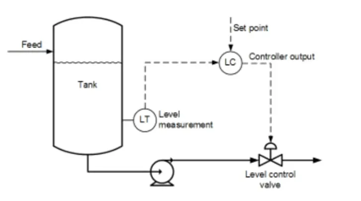
Fig. 2: A simple Instrumentation System
Assume that you have a tank whose level has to be maintained in such a way that the water in the tank must not go above 75% of the height of the tank.
Now, as in this picture (Fig. 2), we mounted a level sensor on the top of the tank. This sensor will be calibrated in such a way that it will sense when water reaches the desired set point.
Here the set point is 75% of the tank. As the water reaches the desired set point, it will send a signal to the controller.
The controller will now generate a corrective output and send it to the final control element which is the valve in this case.
As the water is more than the setpoint, the valve will now open and the water in the tank will drain out until it is below 75% of the tank height. This will continue as the water level fluctuates in the tank.
There are many ways to optimize the process below, which we’ll learn in the upcoming articles.
Hence, broadly, Instrumentation engineering is a specialization engineering branch for studying the basics of measuring instruments used in the design and configuration of automated systems in electrical, electronics, and pneumatic domains, etc. The majority of instrumentation engineers work in industries for automation and control of processes. Instrumentation and control systems optimize systems for increased productivity, reliability, safety, and stability. Several devices like microprocessors, microcontrollers, or PLCs are used to measure and control the system parameters.
Thank you for reading! Share your thoughts on this post in the comments section below! Let me know what you’d like to learn more about!
An accelerometer is an electro-mechanical device that measures the acceleration of motion of a pipe, equipment, or structure. This is a very useful tool for vibration engineering and is widely used to measure vibration in operating plants. The vibrating force produces an electrical signal which is captured by the sensors of the accelerometers. The use of accelerometers helps maintenance and inspection engineers understand a machine’s stability and help them monitor it to take future decisions. In this article, we will learn more about accelerometers, their working, function, selection, and types.
Working Principle of an Accelerometer
Accelerometers use sensors to sense static or dynamic acceleration forces. Static acceleration is created due to the constant forces that act on an object like gravity force or friction force. These forces are known and uniform and can easily be calculated to a large extent.
On the other hand, dynamic acceleration forces like vibration or shock are sudden, non-uniform, and can not be easily predicted. The accelerometers can detect and measure the acceleration on one, two, or three axes and convert it into electrical signals.
In general, accelerometers are equipped with internal capacitive plates. Some of these are fixed, while others are attached to minuscule springs. When an acceleration force acts upon the sensor, these plates move internally in relation to each other to cause capacitance change between them. The acceleration is then determined from these changes in capacitance.
Some other types of accelerometers use piezoelectric materials which provide an electrical charge (voltage) when placed under acceleration. There are even more types that use the piezoresistive effect, hot air bubbles, and light.
Types of Accelerometers
To efficiently serve the industry to resolve vibration problems by measuring it, there are broadly three types of accelerometers. they are:
Piezoelectric accelerometer
Piezoresistance accelerometer, and
Capacitive accelerometer.
Piezoelectric Accelerometer
This type of accelerometer uses piezoelectric materials to sense the acceleration change and is used for shock and vibration measurement. There are two types of piezoelectric accelerometers; High impedance charge output accelerometer and low impedance output accelerometer.
In a High impedance charge output accelerometer, the electrical charge produced by the piezoelectric crystal is connected directly to the measurement instruments. The charge output needs special accommodations and instrumentation. This type of accelerometer can be used even for high-temperature applications (>1200C) when low-impedance models can not be used.
The low-impedance accelerometer consists of a tiny built-in micro-circuit and FET transistor. These elements convert the electric charge into a low-impedance voltage that any standard instrumentation can easily interface. This type of accelerometer is normally used in industry. OMEGA(R) accelerometers are mainly this type of low impedance accelerometers.
Piezoresistance Accelerometer
Piezoresistance accelerometers are much less sensitive than piezoelectric accelerometers and are mainly used for vehicle crash testing. A piezoresistance accelerometer senses the amount of pressure applied to it and increases its resistance in proportion.
Capacitive Accelerometer
The capacitive accelerometer is the most commonly used type of accelerometer. An object’s acceleration is determined by the change in electrical capacitance.
Uses of Accelerometers
Accelerometers find a wide range of applications in industries. They are used in the most complex machines and even handheld devices like smartphones. Some of the real-world applications of accelerometers are listed below:
Digital Devices: To rotate the display based on the orientation of holding, smartphones, tablets, and digital cameras use accelerometers.
Vehicles: Accelerometers are responsible for triggering airbags during a vehicle accident. The accelerometers installed in the cars send a signal when it experiences a sudden shock.
Drones: Drones stabilize their orientation mid-flight with the help of accelerometers.
Rotating Machinery: The vibrations in any component in rotating machinery are measured by accelerometers and then studied to find the cause of vibration.
Industrial Platforms: Accelerometers are used to measure platform stability or tilt.
Vibration Monitoring: To monitor the vibration of any equipment, piping, or other structural component accelerometers are proved to be very useful.
Sports: The wearable devices of athletes comprise accelerometers or gyroscopes to track improvements.
Medical Industry: Physicians use accelerometers to check gain in body mass and monitor body movements. The heart rate measuring device also uses this device.
Even using accelerometers, Zoologists track animal movement inside the jungles.
Some other applications of accelerometers include the following:
The proper selection of an accelerometer depends on various parameters as listed below:
Vibration amplitude and frequency range are to be monitored.
Temperature range of the pipe/equipment requiring vibration measurement.
Size and shape of the sample to be monitored
Working environment
Presence of electromagnetic fields and noise
Requirement of Intrinsically safe or explosion-proof instruments.
Output required; analog or digital.
The number of axes for measurement; one, two, or three-axis measurement.
Maximum swing required.
Sensitivity required.
Bandwidth required.
Power requirement.
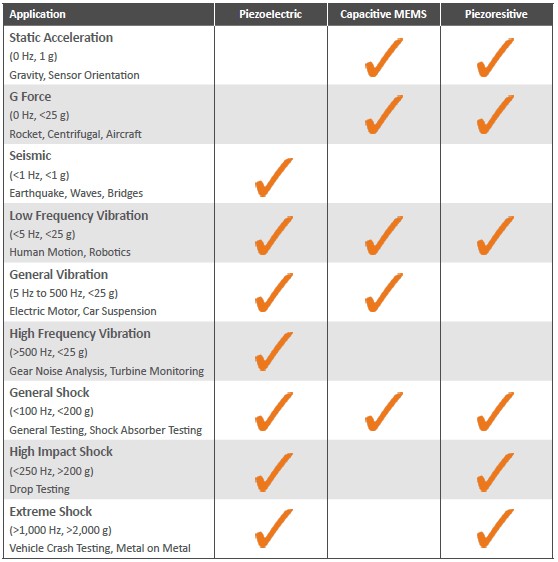
The following image (Courtesy: blog.endaq.com) provides a typical guideline for selecting an accelerometer.
Fig. 1: Selection of Appropriate Accelerometer
Mounting an Accelerometer
For proper mounting of any device, it is always better to read and follow the manufacturer’s manual. In general, the sensor is directly mounted to the machine’s surface where vibrations need to be measured. There are several types of mounting methods for direct surface mounting including:
Flat Magnet Mount
2-pole Magnet Mount
Adhesives (Epoxy/Cyanoacrylate)
Mounting Stud
Isolating Stud
Magnet Mounts are used for temporary mountings on ferromagnetic materials. This type of mounting allows the sensor to be easily relocated from one location to the other for multiple readings. For mounting on a curved ferromagnetic surface, two-pole magnetic mounts are used.
Adhesives such as epoxy or cyanoacrylate and threaded studs are normally considered for permanent mountings. Mounting studs provide solid reliable mountings but require the structure to be drilled and tapped.
Characteristics of an Accelerometer
All accelerometers should possess the following characteristic features:
Rugged and durable
High stiffness
Very repeatable
Wide dynamic range
Fast rise time
High-useable frequency range
Communication Interface
Accelerometers communicate over an analog, digital, or pulse-width modulated connection interface.
Analog Accelerometers show accelerations through varying voltage levels which normally fluctuate between the ground and the supply voltage level. Analog accelerometers are cheaper than digital accelerometers.
Digital Accelerometers communicate over SPI or I2C communication protocols which have more functionality and are less susceptible to noise than analog accelerometers.
Accelerometers with output data over pulse-width modulation (PWM) output square waves with a known period, but a duty cycle that varies with changes in acceleration.
What is Metal Grating? Types and Uses of Metal Gratings
Metal grating is a very useful perforated metal product widely used as floors, trench covers, mezzanines, trailer beds, scaffolding, stair treads, fencing, grills, bridges, fire escapes, and maintenance platforms in various industries. They are produced by perforating metal sheets or joining metallic bars to form a grid. Various manufacturing methods like expansion, perforation, molding, welding, etc are used to produce metal gratings.
The most common metals that are used to make metal gratings are iron, carbon steel, aluminum, and stainless steel. Metal gratings must have sufficient strength to carry the load and should have a non-slip safe surface to serve as a secure work platform.
Types of Metal Gratings
To cater to the different industry application needs, various types of metal gratings are produced. The specific type of metal grating selection depends on some parameters like:
thickness,
metal bar dimensions,
the configuration or pattern of the gaps or openings, which include oval, square, and diamond shapes.
load to be carried,
the work environment where used, etc.
In the following section, we will discuss the most common metal grating types.
Metal Grating Types
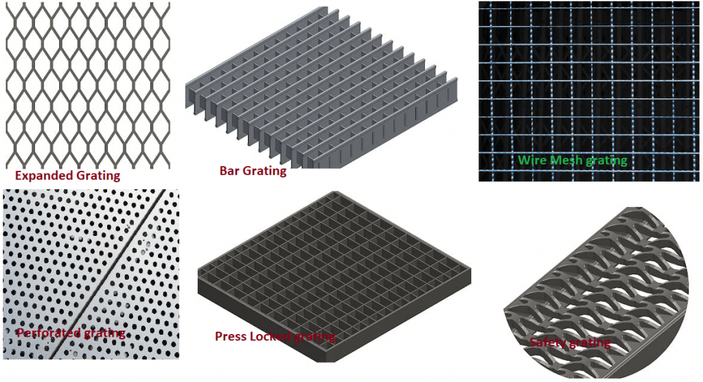
Expanded Metal Gratings
Expanded metal grating is produced by puncturing slits in a metal sheet. After the slits are cut, the metal sheets are stretched and pulled to expand them. Because of this expanding action, this type of metal grating is known as expanded metal grating. A diamond-shaped pattern with a slip-resistant surface is generated in the grating. The completed sheets are then cut to the required size to fit the application requirement. Common metals that are used to produce this type of metal gratings are carbon steel, stainless steel, and aluminum.
No waste is created while making expanded metal gratings and hence, this is very economical. The sheets have good structural strength. A Standard expanded process along with cold rolling to flatten the surface to a smooth even finish is usually used during manufacturing. Expanded metal grates are widely used in flooring, fences, security applications, steps, etc.
Bar Metal Grating or Bar Grating
This is the most common type of metal grating. Bar metal grating is constructed of parallel bars connected together to perpendicular bars using various methods like welding, riveting, press-locking, close meshing, etc. The joining method for bar grating is decided based on the thickness of the bars, the material being used, and the cost.
Steel and Aluminum are the most common metals to produce bar metal grating. Due to their high strength-to-weight ratio, they are used in industrial flooring, street drains, fire escapes, and bridges.
Fig. 1: Types of Metal Gratings
Wire Mesh Metal Grating
Wire mesh metal grating is also popular by names like wire cloth, wire fabric, wire grating, etc. This type of metal grating is produced by using rows and columns of intersecting wires. The popularity of wire mesh grating is due to its easy installation, high durability, flexibility, and versatility.
Depending on the manufacturer, wire mesh metal grating can be welded or woven. Welded wire metal grating is welded at locations where the row and columns intersect. On the other hand, woven wire metal grating is woven like cloth and thus has an array of intersecting wires with columns and rows going over and under at their connecting points.
Wire mesh metal grating is used for Separation and filtration, Security work, Ventilation, Screening and fencing, Material reinforcement, etc.
Perforated Metal Grating
Perforated metal grating is also known as perforated screen, perforated sheet, or perforated plate. They are produced by stamping, punching, or deforming metal sheets to create holes of a specific size, pattern, and shape. Exceptionally sturdy metals like stainless steel, carbon steel, and aluminum are used as metal sheets to make this type of metal grating. Holes are made by different metal fabrication processes like rotary pinning, die punching, laser cutting, etc.
Common applications of perforated metal grating are sound reduction, ventilation, screening, chemical purification, centrifuging, construction material development, etc.
Safety Grating
Also known as Grip Strut Grating, Safety grating provides a firm, solid, and skid-resistant walking surface. These types of metal gratings are designed to increase traction and prevent stumbling, slips, and falling. Small diamond protrusions are usually used in safety grating for greater grip and traction. The open surfaces prevent the accumulation of liquids and help in drainage and airflow. The increased grip of safety metal grating is due to the serration of the edges of the diamond openings created by cold stamping. Steel and Aluminum are the common materials for safety grating.
Compound Metal Grating
Compound metal grating is produced by combining two forms of grating and generally includes bar grating and steel plate grating. Usually, they are composed of a checkered plate sealed to the surface of a steel bar metal grating, with 3 mm to 6 mm steel plates. Compound metal grating is available in a variety of sizes and material types.
Press Locked Metal Grating
In Press locked metal grating, the cross and bearing bars are notched and pressed together and hence the name. They have a smooth even surface across the joined bars. Pressed locked metal gratings have an aesthetically appealing appearance and are generally produced from Steel and Aluminum with a wide variety of sizes and bar openings.
Common Materials Used to Make Gratings
Grating usually refers to any type of covering or frame used to cover holes, provide protection, offer support, or serve as a platform. A wide variety of materials can be used to manufacture grating. Even sturdy plastics can be used to make gratings.
In general, the metallic grating is more popular because of its strength and ability to adjust to many environmental conditions. Specialized metal gratings are used in various industries, airports, and manufacturing facilities and are very strong and durable.
Common materials used for manufacturing metal gratings are:
Aluminum
Light Duty Steel Metal
Stainless Steel
Galvanized Steel
Heavy Duty Carbon
Applications of Metal Grating
The most common use of metal grating is to protect workers by providing a secure, stable, and firm work surface with excellent traction. Additionally, they are placed to provide a barrier in unsafe or hazardous situations to prevent accidents. Some of the common uses of metal gratings can be listed as follows:
Metal Gratings for Buildings: In building services, metal gratings can be used as flooring, walkways, platforms, and mezzanines to provide a safe, strong, and durable structure and a protective barrier.
Gratings in Filtration Systems: Due to their corrosion resistance and exceptional strength, metal gratings are popular in water filtration systems. They can easily capture plastic bags, boxes, and other forms of garbage.
Floor Metal Grating: Metal grading is widely used for flooring. In marine and wastewater conditions, Aluminum floor grates are used. For heavy-duty applications, steel metal floor grating is normally used.
Fencing with Metal Grating: Due to the aesthetically appealing appearance, high strength, and rigidity metal gratings find applications as fencing.
Sump Covers: Steel bar grating is used to cover pits or sumps where chemicals or water are collected.
Loading Ramps: Metal gratings also find applications as loading ramps for loading and unloading heavy cargo into elevated platforms or vehicles.
Rail Cars: A bar grating is usually used for running boards, brake steps, walkways, and platforms in locomotives, freight cars, or railcars.
Some other applications include:
Bridge Sidewalks
Concrete Reinforcement
Dipping Trays
Drainage Covers
Fire Escapes
Fork Lift Traffic
Ladder Treads
Landing Mats
Light Guards
Machine and Motor Bases
Machine Bases
Machinery Safety Guards
Machinery Support
Material Screens
Motor Bases
Ornamental Grills
Overhead Signs
Paint Booths
Partitions
Racks & Shelving
Ramps
Running Boards
Security Screens
Snow Fences
Solar Screens
Stage Flooring
Stairs
Strainers
Tree & Pole Guards
Trench Covers
Trenches
Truck Beds
Truck Grills
Ventilating Screens
Wash Racks
Window Guards
Metal Grating Standards
Metal grating standards and codes are guidelines and specifications established by various organizations to ensure the quality, safety, and performance of metal gratings used in different applications. These standards provide manufacturers, engineers, and users with a common set of criteria for designing, testing, and installing metal gratings. Compliance with these standards helps ensure that metal gratings meet industry requirements and are suitable for their intended use. Some of the prominent standards and codes related to metal gratings include:
ANSI/NAAMM MBG 531: Metal Bar Grating Manual: This manual, published by the National Association of Architectural Metal Manufacturers (NAAMM), provides guidance for the design, fabrication, and installation of metal bar gratings, including specifications for different types of gratings.
ANSI/NAAMM MBG 532: Heavy Duty Metal Bar Grating Manual: Another publication by NAAMM, this manual focuses specifically on heavy-duty metal bar gratings, providing guidelines for their design and application in high-load environments.
ASTM A123/A123M: Standard Specification for Zinc (Hot-Dip Galvanized) Coatings on Iron and Steel Products: This ASTM International standard specifies the requirements for hot-dip galvanizing of steel, which is a common surface treatment for metal gratings to enhance corrosion resistance.
ASTM A1011/A1011M: Standard Specification for Steel, Sheet and Strip, Hot-Rolled, Carbon, Structural, High-Strength Low-Alloy, High-Strength Low-Alloy with Improved Formability, and Ultra-High Strength: This standard covers the requirements for hot-rolled carbon steel used in the fabrication of metal gratings.
ISO 14122 series: Safety of Machinery – Permanent means of access to machinery – Part 4: Fixed ladders: The ISO 14122 series of standards provide guidelines for the design and construction of fixed ladders, which are often integrated into metal grating structures.
AS1657: Fixed Platforms, Walkways, Stairways, and Ladders – Design, Construction, and Installation: This Australian Standard outlines the requirements for the design, construction, and installation of fixed platforms, walkways, stairways, and ladders, including those that use metal gratings.
OSHA (Occupational Safety and Health Administration) regulations: In the United States, OSHA sets safety standards for workplaces, including requirements for the design and use of stairs, platforms, and walkways, which may involve metal gratings.
It’s important to note that metal grating standards and codes may vary based on the country, industry, and application. Manufacturers and designers should refer to the appropriate standards that align with their specific needs and locations. Compliance with these standards ensures that metal gratings meet safety, quality, and performance requirements, providing reliable and safe solutions for their intended use.
How are Metal Gratings Made?
Metal gratings are typically made through a process called metal bar grating fabrication. The exact steps and techniques may vary depending on the type and application of the grating, but here is a general overview of the manufacturing process:
Material selection: The first step is to choose the appropriate type of metal for the grating, based on factors such as the intended application, load-bearing capacity, corrosion resistance, and environmental conditions. Common metals used for gratings include steel, aluminum, stainless steel, and other alloys.
Cutting the bars: Metal bars, which are the primary components of the grating, are cut to the desired length using various cutting methods like shearing, sawing, or laser cutting.
Shaping and hole punching: The metal bars are then shaped and perforated to create the desired pattern. This involves stamping or punching holes through the bars in a regular grid pattern. The hole size and spacing determine the open area and load-bearing capacity of the grating.
Joining bars and cross rods: For certain types of gratings, cross rods are attached to the main bars to form the final grating panel. Different methods like welding, swaging, or riveting may be used to securely join the bars and cross rods.
Surface treatment: Depending on the application and environmental conditions, the metal grating might undergo surface treatment to enhance its properties. This can include processes like galvanizing (hot-dip or electro), painting, or applying other coatings to improve corrosion resistance.
Cutting to size: Once the grating panels are assembled and treated, they may be cut to the required dimensions to fit the specific installation locations.
Quality control: Before being shipped to customers, the metal gratings undergo rigorous quality control checks to ensure they meet industry standards and specifications.
What are Metal Grating Sheets
Metal grating sheets are large, flat panels made from metal bars that have been welded, press-locked, or riveted together in a grid pattern. They are commonly used for various industrial, commercial, and architectural applications due to their strength, durability, and open design, which allows for efficient drainage and ventilation. Metal grating sheets are available in different materials, such as steel, aluminum, stainless steel, and other alloys, each with specific properties suitable for different environments and applications.
The primary components of metal grating sheets are the bearing bars (metal bars running parallel to each other) and cross rods (bars that intersect and connect the bearing bars). The grid pattern formed by these bars creates an open and stable structure with excellent load-bearing capabilities.
Metal grating sheets are versatile and can be customized to fit specific project requirements. They can be further processed by cutting, bending, or galvanizing to enhance their performance and durability. Depending on the intended use, metal grating sheets may also undergo surface treatments, such as painting or coatings, to improve corrosion resistance and appearance.
Metal Grating Deck
A metal grating deck refers to a platform or flooring surface constructed using metal gratings. It consists of metal grating sheets that are assembled and secured to create a stable and open structure, providing a safe walking or working surface. Metal grating decks are commonly used in various industrial, commercial, and architectural applications due to their strength, durability, and excellent drainage and ventilation properties.
The term “deck” in this context refers to a flat, horizontal surface that is elevated above the ground or floor level. Metal grating decks are often installed on steel or aluminum frameworks, providing a strong and reliable support system. They can be found in various settings, including:
Industrial platforms: Metal grating decks are used as elevated walkways, mezzanines, and work platforms in industrial facilities. They allow workers to access equipment, machinery, or storage areas safely.
Outdoor bridges and walkways: Metal grating decks are commonly used in pedestrian bridges and outdoor walkways, especially in areas where corrosion resistance and durability are essential.
Rooftop walkways: In commercial and industrial buildings, metal grating decks are sometimes used as rooftop walkways to provide safe access for maintenance and inspection.
Stair treads and landings: Metal grating decks can be used as stair treads and landings, offering an anti-slip surface and enhancing safety in staircases.
Catwalks and access platforms: In industrial settings, metal grating decks are often used as catwalks or access platforms to reach equipment and machinery at elevated heights.
Metal grating decks are available in different types, such as welded bar grating, press-locked grating, and riveted grating, each with specific load-bearing capacities and open area percentages to suit different applications and requirements. They can also be customized in terms of material, dimensions, and surface treatments to meet specific project needs.
Metal Grating Stairs
Metal grating stairs are staircases that incorporate metal gratings as the stair treads and landings. They are designed with an open and durable structure, providing several benefits such as improved traction, drainage, and ventilation. Metal grating stairs are commonly used in various industrial, commercial, and outdoor settings where safety, strength, and resistance to environmental elements are essential.
The main components of metal grating stairs include:
Stair Treads: The horizontal surfaces of the stairs that people step on while ascending or descending. These treads are made from metal gratings, which are designed to offer a slip-resistant surface, allowing for safe movement on the stairs.
Stringers: The vertical supports on either side of the stairs that provide stability and carry the load of the stair treads and the weight of individuals using the stairs.
Handrails: Metal grating stairs often have handrails on one or both sides, providing additional support and safety for users.
Metal grating stairs can be found in various applications:
Industrial settings: They are commonly used in industrial facilities, factories, and warehouses where stairs need to withstand heavy foot traffic and where there may be potential for liquids or debris on the stairs. The open design of metal grating stairs allows for easy drainage of liquids and prevents the accumulation of dirt.
Outdoor environments: Metal grating stairs are frequently used in outdoor areas, such as pedestrian bridges, boardwalks, and access stairs for recreational facilities or waterfront locations. The open structure helps prevent the buildup of water or ice, reducing the risk of slipping.
Fire escapes: Metal grating stairs are often used in fire escape systems, providing a safe and quick means of exit in case of emergencies.
The type of metal grating used for stairs may vary based on the application, load requirements, and environmental conditions. Common materials include steel, aluminum, and stainless steel, each offering different properties such as strength, corrosion resistance, and weight-bearing capacity. Additionally, metal grating stairs can be customized to meet specific project requirements, including size, shape, and finish.
Metal Grating Walkway
A metal grating walkway refers to a raised, open, and structured pathway constructed using metal gratings. It is designed to provide a safe and stable surface for pedestrians to walk on while allowing for efficient drainage and ventilation. Metal grating walkways are commonly used in various industrial, commercial, and public settings where there is a need for elevated pathways and walkable surfaces.
Key characteristics of metal grating walkways:
Open structure: Metal gratings used in the walkways have a grid-like pattern, typically consisting of bearing bars (longitudinal bars) and cross rods (transverse bars). This open design ensures that rainwater, snow, and debris can pass through the grating, reducing the risk of slipping and maintaining a clean walking surface.
Strength and durability: Metal grating walkways are capable of withstanding heavy foot traffic and loads, making them suitable for industrial environments, factory floors, construction sites, and other areas with high pedestrian activity.
Customization: Metal grating walkways can be customized to suit specific project requirements in terms of size, shape, material, and surface treatment. They are available in various materials, such as steel, aluminum, stainless steel, and other alloys, each offering different properties suited for particular applications.
Safety features: Metal gratings used in walkways are often designed with serrated surfaces or anti-slip coatings to enhance traction and reduce the risk of accidents, especially in wet or slippery conditions.
Decorative Metal Gratings
Decorative metal gratings are metal grating panels designed with an aesthetic focus, serving both functional and ornamental purposes. They combine the strength and durability of traditional metal gratings with decorative patterns or designs to enhance the visual appeal of spaces. Decorative metal gratings are widely used in architectural and interior design applications, offering a unique blend of style and practicality.
Key features of decorative metal gratings:
Aesthetics: Decorative metal gratings come in a variety of patterns, shapes, and artistic designs that can complement the overall theme of a building or space. They add an element of visual interest and can be used as decorative accents, facades, or screens.
Versatility: These gratings can be used in a range of applications, including decorative cladding, fencing, room dividers, sunscreens, and facade elements, allowing architects and designers to incorporate them creatively into their projects.
Material choices: Decorative metal gratings are available in different materials, such as brass, bronze, stainless steel, and aluminum, offering various colors and finishes to suit specific design requirements.
Customization: Like standard metal gratings, decorative metal gratings can be custom-made to fit specific dimensions and design preferences, providing flexibility in design.
Overall, decorative metal gratings combine functionality and aesthetics, making them a popular choice for architects, designers, and building owners looking to add visual interest and unique design elements to their spaces.
What is the Unified Numbering System (UNS) for Metals and Alloys?
To overcome the problems of traditional material numbering systems developed during the 1960s for distinguishing each material separately and standardize, a study was conducted. After an 18-month feasibility study and discussions with AISI, the Aluminum Association, the Copper Development Association, and the Steel Founders’ Society of America, the team recommended establishing the Unified Numbering System (UNS). The UNS numbering system is used by many engineering industries and is accepted globally.
What is a Unified Numbering System
The Unified Numbering System or UNS is a metal and alloy designation system managed jointly by ASTM International and SAE International. Each specific metal or alloy is assigned a UNS number that defines mainly its specific chemical composition, and sometimes specific mechanical or physical properties. So, the unified numbering system basically is a composition-based material numbering system where each metal/alloy is identified with a letter followed by five numbers.
Note that, a UNS number alone does not serve as the full specification of that material as it does not establish any requirements for material properties, heat treatment, form, or quality. A document SAE HS-1086 gives a cross-reference for various designation systems and the chemical composition of materials. Currently, there are more than 5200+ UNS designations for different metals and alloys.
Difference between UNS number and Material Specification
A UNS number only provides a specific chemical composition. The full material specification is not provided in the UNS number. Other material requirements such as mechanical properties, heat treatment, form, purpose, and testing methods are specified in the respective material specification. Various trade and professional organizations prepare these material specifications. Within a material specification, a number of different UNS numbers may be included.
UNS Number Format
Each UNS number is structured with a letter followed by five digits that designate the composition of the material. They have 18 series to identify metals and alloys. Out of these 18 series, 9 are for ferrous metals and alloys and the other 9 are for non-ferrous metals and alloys.
Letters used in the unified numbering system are A for Aluminum and Aluminum alloys, C for copper and copper alloys, D for specified mechanical property steels, E for Rare earth and rare earthlike metals and alloys, F for cast Irons, G for AISI and SAE carbon and alloy steels, H for AISI and SAE H-steels, J for Cast steels, K for Miscellaneous other steels and ferrous alloys, L for Low-melting metals and alloys, M for Miscellaneous nonferrous metals and alloys, N for Nickel and nickel alloys, P for Precious metals and alloys, R for Reactive and refractory metals and alloys, S for Stainless Steels, T for Tool Steels, W for Welding filler metals, and Z for Zinc and zinc alloys.
The first 3 digits usually match older 3-digit numbering systems, while the last 2-digits indicate modern variations. To give an example, Stainless Steel Type 310 in the original 3-digit system became S31000 in the UNS System. The more modern low-carbon variation, Type 310S, became S31008 in the UNS System. Sometimes the suffix digits represent a material property specification. For example, “08” in UNS S31008 represents the maximum allowed carbon content of that material is 0.08%.
Examples of Unified Numbering System for Common materials
Some of the common materials and translations to other standards are:
UNS S31600 is SAE 316
UNS K11547 is T2 tool steel
UNS S17400 is ASTM grade 630, Cr-Ni 17-4PH precipitation hardened stainless steel
UNS S30400 is SAE 304, Cr/Ni 18/10, Euronorm 1.4301 stainless steel
UNS S31603 is 316L, a low-carbon version of 316. The digit “03” was assigned since the maximum allowed carbon content is 0.03%
UNS C90300 is CDA 903
Refer to the table below which provides the description of numbers in the UNS numbering system.
A00001-A99999
Aluminum and aluminum alloys
A01001-A63562
Aluminum Foundry Alloys, Ingot, or Casting
A82014-A87475
Wrought Aluminum Alloys Clad with Wrought Aluminum Alloys, Non- or Heat Treatable
A91030- A91450
Wrought Aluminum Alloys, Non-Heat Treatable
A93002-A95954
Wrought Aluminum Alloys, Non-Heat Treatable
A98001-A98280
Wrought Aluminum Alloys, Non-Heat Treatable
A92001-A92618
Wrought Aluminum Alloys, Heat Treatable
A96002-A97472
Wrought Aluminum Alloys, Heat Treatable
C00001-C99999
Copper and copper alloys
Wrought Alloys
C10100-C15760
Pure and Low Alloyed Copper (>99%Cu)
C16200-C16500
Cadmium Copper
C17000-C17700
Copper-Beryllium Alloy (Beryllium Bronzes)
C18000-C19900
Copper and High Copper Alloys (>96%Cu)
C20500-C29800
Brasses (Cu-Zn)
C31000-C35600
Leaded Brasses (Cu-Zn-Pb )
C40400-C49080
Tin Brasses (Cu-Zn-Sn-Pb)
C50100-C52900
Phosphor bronzes (Cu-Sn-P)
C53200-C54800
Leaded Phosphor Bronzes
C55180-C56000
Cu-Ag-P and Cu-P Brazing Filler Metal
C60600-C64400
Aluminum Bronzes
C64700-C66100
Silicon Bronzes
C66200-C66420
Copper Alloys
C66700-C67820
Manganese Bronzes
C68000-C69950
Silicon Brasses and Other Copper-Zinc Alloys
C70100-C72950
Copper-Nickel Alloys
C73150-C79900
Nickel Silvers and Leaded Nickel Silvers
Cast alloys
C80100-C81200
Cast Coppers (>99%Cu)
C81300-C82800
Cast Chromium Copper and Beryllium Copper Alloys (>96%Cu)
C83300-C85800
Cast Red, Yellow and Leaded Brasses
C86100-C86800
Cast Manganese Bronzes and Leaded Manganese Bronzes
C87300-C87900
Cast Silicon Brasses and Bronzes
C89320-C89940
Cast Cu-Sn-Bi-(Se, Zn, Ni) Alloys
C90200-C94500
Tin Bronzes and Leaded Tin Bronzes
C94700-C94900
Cast Nickel-Tin Bronzes
C95200-C95810
Cast Aluminum Bronzes
C96200-C96800
Cast Copper-Nickel Alloys
C97300-C97800
Cast Nickel-Silver Alloys
C98200-C98840
Cast Leaded Copper Alloys
C99300-C99750
Cast Copper Alloys
D00001-D99999
Steels with specified mechanical properties
D40450-D40900
Carbon Steels
D50400-D52101
Alloy Steels Casting
E00001-E99999
Rare earth and rare earth-like metals and alloys
E00000-E00999
Actinium
EO1000-E20999
Cerium
E21000-E45999
Mixed rare earth
E46000-E47999
Dysprosium
E48000-E49999
Erbium
E50000-E51999
Europium
E52000-E55999
Gadolinium
E56000-E57999
Holmium
E58000-E67999
Lanthanum
E68000-E68999
Lutetium
E69000-E73999
Neodymium
E74000-E77999
Praseodymium
E78000-E78999
Promethium
E79000-E82999
Samarium
E83000-E84999
Scandium
E85000-E86999
Terbium
E87000-E87999
Thulium
E88000-E89999
Ytterbium
E90000-E99999
Yttrium
F00001-F99999
Cast irons
F 10001-F15501
Cast Iron, Gray
F 10090-F10920
Cast Iron Welding Filler Metal
F 20000-F22400
Cast Iron, Malleable
F 22830-F26230
Cast Iron, Pearlitic Malleable
F 30000-F36200
Cast Iron, Ductile (Nodular)
F 41000-F41007
Cast Iron, Gray, Austenitic
F 43000- F43030
Cast Iron, Ductile (Nodular), Austenitic
F45000 F 45009
Cast Iron, White
F47001-F47006
Cast Iron, Corrosion
G00001-G99999
AISI and SAE carbon and alloy steels (except tool steels)
Martensitic Cr Stainless Steel; Ferritic Cr Stainless Steel with Ti or Ni or Mo; Martensitic Cr-Ni-Mo Stainless Steel; Hardenable Cr Stainless Steel
S50100-S50500
Cr Heat Resisting Steels and Filler Metal
S63005-S64007
Valve Steel
S65006-S65007
Valve Steel
S65150-S67956
Iron Base Superalloy
T00001-T99999
Tool steels, wrought, and cast
T11301-T12015
High-Speed Tool Steels
T20810-T20843
Hot-Work Tool Steels
T30102-T 30407
Cold Work Tool Steels
T31501-S31507
Oil-Hardening Steels
T41901-T41907
Shock-Resisting Tool Steels
T51602-T51621
Mold Steels
T60601-T60602
C-W Tool Steels
T61202-T61206
Low-Alloy Tool Steels
T72301-T72305
Water Hardening Tool Steels
T74000-T75008
Cr-Steels Solid Welding Wire for Machinable Surfaces and Tool and Die Surfaces
T87510-T87520
Thermal Spray Wire
T90102-T91907
Cast Tool Steels
W00001-W99999
Welding filler metals, classified by weld deposit composition
W60000-W69999
Copper base alloys
W70000-W79999
Surfacing alloys
W80000-W89999
Nickel base alloys
Z00001-Z99999
Zinc and zinc alloys
Table 1: UNS Numbering System for Metals and Alloys
Importance of UNS (Unified Numbering System)
Various trade associations, societies, and individual users and producers of metals and alloys use the UNS system to avoid confusion. The system provides a uniform approach and proficient indexing which helps in record keeping, data storage, retrieval, and cross-referencing. Using UNS numbers metal and alloy identification becomes much easier.
Aluminum pipes and tubes are soft and ductile and their color resembles the color of silver. Due to its low density and lightweight along with decent corrosion resistance capability, aluminum pipe and tubes are preferred in many applications like healthcare, aerospace, recreation products, machine parts, automobile, and transportation hydraulic systems, solar power, refrigerators, and air conditioning systems, brakes, fuel lines, frames, etc. When exposed to a corrosive environment, aluminum forms a passive coating that stops further corrosion. Pure Aluminum is not used for industrial piping applications. Whatever aluminum pipe is commercially available is basically made from aluminum alloys combined with alloying elements like zinc, copper, manganese, magnesium, and silicon.
Aluminum Pipes & Tubes vs Steel Pipes and Tubes
Strength: Aluminum pipe and tubes have lower strength as compared to steel piping and tubing. Both the yield strength and tensile strength of aluminum pipes are much lower compared to steel pipes. Roughly Steel pipes are 3 times stronger than aluminum pipes.
Density and Material Weight: For the same size and thickness, Aluminum pipes and tubes are lighter as compared to steel pipes. The density of aluminum pipes is lower than steel pipes.
Manufacturing: Aluminum Tubing & Piping are manufactured mainly by extrusion process by forcing a die whereas for steel piping extrusion process is mainly employed for small diameter pipes. Large-diameter steel pipes are usually welded. Aluminum pipes can also be made using spiral welding and the electric resistance welding process.
Alloys Used in Aluminum Pipes and Tubes
Common alloying additions with aluminum are magnesium, manganese, copper, zinc, and silicon. Each of these alloying elements adds different properties to the base metal. The aluminum alloy grades that are popular as pipe and tube are 2024, 3003, 6005, 6041, 6061, 5052, 6063, 6064, 6082, 6105, 6262, 6351, and 7075. ASTM B241/B241M governs the specification of Aluminum pipes and tubes.
Aluminum Pipe Codes and Standards
The piping system is designed following ASME B31.3. Various ASTM codes for aluminum pipe and tube specifications are:
ASTM E155 (Aluminum casting),
ASTM B210 (Seamless tubes),
ASTM B241 (Seamless Pipe and Seamless extruded tubes),
ASTM B345 (Seamless pipe and extruded tube for oil and gas transmission and distribution piping),
ASTM B361 (Aluminum and Aluminum alloy welded fittings),
ASTM B247 (Aluminum fittings),
ASTM B491 (Extruded round tubes for general-purpose applications),
ASTM B547 (Formed and arc welded round pipe and tube)
Aluminum Pipe Sizes
A wide range of Aluminum pipe and tube sizes are available. Commercially available common aluminum pipe size ranges are 1/8″ to 12″. However, custom sizes can easily be manufactured based on requirements.
Common aluminum tube sizes range from 1/16″ to 3″
Aluminum tubes are usually used for their lightweight, thermal and electrical conductivity, and corrosion resistance. Alloy grades 7075, 6061, and 2024 are used inside aircraft assemblies as they have a high strength-to-weight ratio and good fatigue resistance.
Applications requiring more strength and corrosion resistance use Alloy 3003. When multiple welded joints are expected, a highly weldable 5052 can be a good choice.
Proper heat treatment is very important for aluminum alloy pipes and tubes as the characteristics of the alloy are determined by the heat treatment.
Parameters for Choosing Aluminum Tubing & Piping
The selection of Aluminum tubing and piping depends on various factors. Some of them are:
The shape of Aluminum Tubing & Piping
Even though circular pipes and tubes are common and widely used, aluminum tubes are available in various other shapes like rectangular, oval, square, or custom shapes. However, other shapes are costly as compared to regular round shapes.
Process parameters
The selection of every metal pipe and tube is governed by various process parameters as mentioned below:
Pressure Rating– this indicates the maximum or minimum pressure the pipe and tubing can withstand. Depending on the pressure the pipe thickness also varies.
Minimum Bend Radius Rating– this informs the amount of deformation a tubing’s cross-sectional area can go through.
Maximum Vacuum Pressure– If the aluminum pipe or tube will be subjected to vacuum pressure.
Temperature Range– The complete range of temperatures (Maximum and Minimum) that the fluid and material will experience.
Characteristic Features of Aluminum Tubing & Piping
Important characteristics that are usually required for aluminum pipes and tubes are:
Finned or Fluted– Aluminum tubes with fins or flutes can easily dissipate heat. For air conditioners, refrigeration, and heat exchanger applications finned tubes are required.
Serializability– Aluminum tubes in certain applications need sterilization using gamma irradiation, dry heat chemical, disinfection, and autoclaving.
Coiled or Spiral– Aluminum tubes must be flexible enough for running in a wrapped reel spring or format.
Multi-Layered– Multilayered tubes are more robust and durable.
Finish of the Aluminum Tubing & Piping
Aluminum pipes and tubes are finished and coated with a definite type of finish, like:
Galvanized– A zinc layer is added for additional corrosion resistance.
Bright Finish– Mirror-polished surfaces are created to have a shiny look.
Plated– Thin layer of another metal is deposited to improve its corrosion resistance and conductivity.
Painted– Pipes and tubes are painted to increase corrosion resistance or for identification purposes.
Aluminum Pipe Fittings and Components
Aluminum pipe fittings connect with aluminum pipe to create secure, leak-free connections. Similar to steel pipes, aluminum pipe fittings are also required for any directional changes or size changes, or branch connections. Almost all variants of aluminum pipe fittings are available similar to steel pipe fittings. They are produced either by casting or forging and usually have threaded, welded, or flanged end connections. Common aluminum pipe fittings and components are: