Managing expensive and labor- ferocious operations to smart software sounds like an easy task, but for EPC companies with extremely complex megaprojects, any functional changes bring time, plutocrats, and trouble to reciprocate. As a result, the EPC sector is hesitant to go through digital metamorphosis. But these days, there’s new instigation behind engineering software enterprise. In fact, the previous year, 76 engineering and construction directors in a Deloitte postelection poll invested in digital tech time. So, what’s driving the new commitment to technology?
COVID-19 Accelerated Digital Transformation
For numerous EPC enterprises, the pandemic twisted their hands. Companies had to deal with a remote workforce, and they demanded increased safety considerations for onsite jobs. The fresh hurdles extended design timelines by over 300%.
The application of digital tools that sped up processes while maintaining safety and quality, is a necessity if enterprises wanted to stay in business. A remote pool needed the relinquishment of collaboration, cloud, and cybersecurity operations. Limited labor forced associations to do more with fewer people, which resulted in the implementation of labor-saving technology to make the utmost of experts ’ time.
For numerous companies, the experience of planting results as a response to COVID- 19 motivated plans for continuing the digital metamorphosis. Numerous companies extended their cooperative and labor-saving tech to further design phases. They started taking advantage of artificial intelligence(AI), machine learning (ML), and smart security.
Some companies are also starting to profit from further sophisticated labor-saviors, for example; independent vehicles to handle figure tasks and cover the design point, 3D printing for the custom corridors, and natural language processing(NLP) to parse vast quantities of paperwork and create reports.
EPC Market Shifts Introduce Challenge and Opportunity
Along with the hurdles the pandemic brought, EPC enterprises are scuffling with other market problems that started well before COVID-19 and continue to grow. To elaborate, in the energy sector, there are more systems for sustainable sources similar to wind and solar. Along the same lines, in the U.S., any major construction design must comply with environmental, social, and governance( ESG) programs. The sector players are changing as well. Non-traditional construction enterprises, backed by ultramodern backing have entered the game, especially in new energy sectors like solar.
To meet these challenges EPC enterprises are looking for collaborators, who can give the demanded expertise. Hydrocarbon Processing magazine predicts, “ In 2030, possessors and contractors will have evolved their approach to constricting toward fostering more open and cooperative connections, with better alignment across parties toward a greater outcome for the project overall, not just individual players. ”
But partnerships bring their own difficulties. As the size of the project platoon increases, it’s harder to manage communication and workflow, raising the threat of cost and schedule overruns. Plus, more players induce further documents, plans, and designs that need to be reused, stored, penetrated, and participated in by the right people at the right time.
EPC companies who successfully handle the present issues will manage not only hurdles but openings for digital transformation that manage a large meta eco-system while delivering improved effectiveness and lesser pungency. With the proliferation of documents, plans, designs, and design data, enterprises are enforcing engineering software to centrally manage and dissect data and documents from distant sources. And virtual models using the structure information operation frame will help engineers across the platoon and the world coordinates the designs, plans, and status for complex shapes.
Companies are also applying technology that enables slender, brisk design completion. For instance, the technical bi-tabulation process(TBE) has long needed engineers to organize and assess dozens of supplier quotes in a labor-ferocious, time-enervating process. However, applications with NLP can read reams of documents, classify the details and induce reports so engineers can concentrate on analysis. Technology similar to NLP not only saves time and plutocrat but improves the TBE results, helping engineers find the optimal supplier selection.
In the quest for time savings and threat mitigation processes, EPC providers will focus on AI-driven workflow to coordinate and manage all the processes, dwindling the liability of expensive miscommunications. And as digital data piles up, data analytics powered by machine learning will turn one experience into a companion for uninterrupted advancements.
Digital Success Encourages Further Digital Transformation
Once EPC brigades dip their toes into the digital waters, the success of original systems will propel them indeed further. According to Deloitte,
“Benefits [of engineering software] are expected to include as much as a potential 10% to 30% reduction in engineering hours, up to 10% reduction in build costs, and up to 20% reduction in operating costs, improving overall margins for E&C firms throughout the entire project life cycle.”
As more companies realize these benefits, they’ll snappily move to extend them, which increases pressure on the sector in general. Players who want to stay in the game will have to get digital.
In fact, technology relinquishment may be the crucial factor separating winners from also-rans in the forthcoming EPC world. Those who get a jump start on the overall digital transformation will realize a first-mover advantage. Numerous clients in fact view digital-centric EPC companies as more dependable and less parlous than others.
Companies that’ve digitized the utmost of their processes and formalized data storehouse will be in a better place, to take advantage of data collection and analysis across the enterprise. Observers on the job point will feed into AI-driven schedule optimizers who insure the outside effective use of workers and outfits. 3D definitions will help contrivers from remote locales unite ahead and during the figure. AI systems will identify safety pitfalls, and augmented reality (AR) will help offsite experts consult with onsite masterminds about problems or repairs.
What is a Forklift? Working and Types of Forklifts for the Construction Industry
In the oil and gas construction industry, efficient material handling is critical. Forklifts play a vital role in ensuring that operations run smoothly, safely, and efficiently. These versatile machines are not only essential for transporting materials but also contribute to maintaining productivity and safety standards on construction sites. Forklifts are one of the most useful and powerful construction vehicles on any job site for handling materials and carrying heavy loads in a safe and secure way. Their versatility makes them indispensable, and so forklifts are found in all construction and building sites wherever heavy loads are to be moved. In this article, we will explore more about industrial forklifts, their types, components, working, and selection.
What is a Forklift?
A forklift is a powered industrial truck designed to lift, move, and transport heavy materials over short distances, typically within warehouses, construction sites, and manufacturing facilities. Equipped with two fork-like prongs at the front, forklifts can lift loads by inserting the forks beneath them and are powered by either internal combustion engines or electric batteries. Their versatility and maneuverability make them essential for various material handling tasks, including loading and unloading goods, organizing inventory, and facilitating efficient operations in diverse industries.
Types of Forklifts
There is a wide range of industrial forklifts to choose from. The most common types of forklifts are listed below:
Warehouse Forklift
Side Loaders
Counterbalance Forklift
Telescopic Forklifts
Heavy-duty Forklifts
Rough Terrain Forklifts
Reach Fork Trucks
Pallet trucks
Walkie Stacker
Order Picker
Warehouse Forklift
It is quite clear from the name itself that the Warehouse forklift is widely used in most warehouses, factories, and job sites. Warehouse forklifts are one of the most common working vehicles used for loading and unloading inventory. Resembling like a golf cart with two forks extending from the front, this type of forklift usually has a loading capacity of up to 5 Tonne.
Side Loaders
Side loaders are widely used in narrow spaces where navigation and turning are very difficult. They are basically a subtype of warehouse forklifts and are generally found in manufacturing industries. The operator stands in a sideways compartment while using this type of forklift. The side loader has the capability to lift and carry the material in the same direction without turning.
Counterbalance Forklift
Counterbalance forklifts have forks in the front and the counterbalance weight in the back. They don’t have any extended arms and they can be driven right up to the material. From the front of the vehicle, the forks directly come out which makes grabbing the inventory easier.
Counterbalance forklifts are produced in electric, gas, or diesel-powered models. Mitsubishi, Crown, and Toyota are some of the popular manufacturers. The 3-wheel variant of the counterbalance forklifts helps the driver to turn easily in circles.
Telescopic Forklifts
This type of forklift is also popular by names like reach forklift, telehandler, or teletruck. Telescopic forklifts are a combination of a forklift and a crane. With a boom and an extending arm, the telescopic forklifts can reach far into the back of delivery trucks and carry materials much higher and farther than usual forklifts.
Their twin forks help in moving pallets off the ground. Companies like JCB, Genie, Bobcat, Haulotte, and Caterpillar manufacture a variety of telescopic forklifts.
Industrial Forklifts or Heavy Duty Forklifts
Also popular as large capacity forklifts, this type of forklift can lift much heavier loads than the standard forklifts. Usual heavy-duty industrial forklift models can lift a maximum weight of 30,000 lbs. However, similar to telehandlers, they cannot lift at awkward angles. NACCO and Mitsubishi are the big names that produce Industrial forklifts.
Rough Terrain Forklifts
Rough Terrain Forklifts are also called Straight mast forklifts. They widely find outdoor applications on uneven, unstable surfaces. Having thick tractor-style pneumatic tires, rough terrain forklifts doesn’t slip on wet or slippery surfaces. Their sturdy tires are difficult to puncture with nails or sharp rocks, and they help with stability and balance while carrying heavy loads on uneven ground.
Rough terrain forklifts are ideal for construction sites. With a traditional straight mast or a telescoping mast, they can handle a weight capacity of 6,000 to 12,000 pounds.
Reach Fork Trucks
Mostly used in warehouses, reach fork trucks can extend their forks out beyond their stabilizing legs into racks. Suitable for tight spaces, this type of forklift can maneuver with narrow aisle ways and lift loads to high heights.
As they have heavy electric batteries and stabilizing legs, reach fork trucks provide inherent stability and do not need counterbalance weight.
Pallet trucks
Pallet Trucks or pallet jacks or pump trucks are specially designed forklifts without any power source. They are small in size and have the limited load-lifting capability. As they are easy to use and fit well into small tight spaces, they are used to raise the pallet enough to clear the ground.
Walkie Stacker
This type of forklift has a unique appearance and provides specific utility. They don’t have cabs and the operator needs to walk behind the stacker to operate.
Order Picker
A sub-type of walkie stacker, order pickers pick the material from storage and deliver it. This type of forklift is designed to lift the operators up. They are produced in versatile designs to handle various sizes.
Depending on fuel option and application, Occupational Safety and Health Administration (OSHA) categorizes forklifts into seven classes as listed below:
Class I – Electric Motor Ride Truck
Class II – Electric Motor Narrow Aisle Truck with Battery as a fuel source
Class III – Electric Motor Hand Truck with Battery as a fuel source
Class IV – Internal Combustion Engine With Cushion Tires with Gas or Diesel as a fuel source
Class V – Internal Combustion Engine Trucks With Pneumatic Tires with Gas or Diesel as a fuel source
Class VI – Electric and Internal Combustion Engine Tractors with Battery, Gas, or Diesel as a fuel source
Class VII – Rough Terrain Forklift Truck with Gas or Diesel as a fuel source.
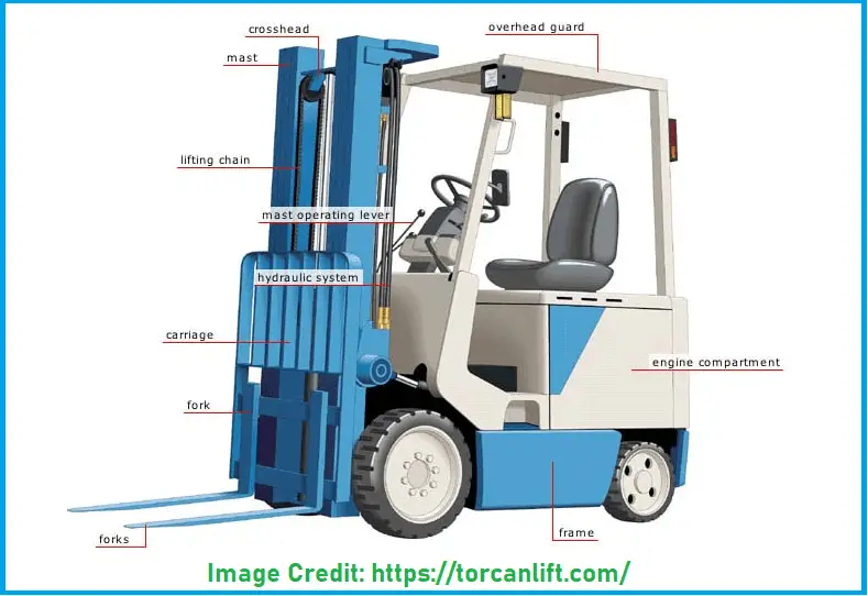
Components of a Forklift
To perform its task effectively a forklift has a variety of components as listed below:
The truck frame serves as the base for all other components.
A counterweight attached to the rear part to counterbalance the lifted weight.
Power Source
A carriage that fastens to the mast rails and moves up and down.
The mast consists of interlocking rails to give horizontal control.
Refer to Fig. 1 below that shows the parts of a forklift.
Fig. 1: Forklift Parts
Working of a Forklift
To carry heavy loads, forklifts use a combination of hydraulic systems and pulley systems.
The hydraulic system uses a series of pistons, cylinders, and hydraulic fluid to lift and lower the loads. A skilled forklift operator uses the lift handle to raise or lower the loads. The hydraulic fluid creates the necessary pressure through its pump, piston, and cylinder mechanism. The fluid pressure creates an upward force to move the piston upwards.
The fork is attached to a pair of roller chain pulleys. When the hydraulic pistons force the mast in the upward direction, the gears on the mast are pressed against the roller chains which move the mast up and pull the fork in the upward direction. Two controls; steering and lifting help the operator to lift loads and move.
Selecting a Forklift
As a wide range of forklifts is available it is really difficult to choose the right forklift. While selecting the ideal forklift for the project, various parameters must be considered. Some of these are:
Load-bearing Capacity–The weight required to lift and at what height.
Space Availability– the forklift selection must consider the space available in the area where it will be used. The height of doorways and openings must be considered.
Power Source– whether electric-powered, battery-powered, or gas/oil-powered.
Surface Terrain–Find out if the ground surface is even or rough.
Stability of the Job site– If the ground can sustain the forklift.
Characteristics of a Forklift
Forklifts are usually characterized by three factors:
Lift Capacity– The amount of weight the forklift can safely handle without losing its stability.
Load Centre– The distance from the forks to the center of gravity of the carried load. Depending on height, weight, lift angle, and tilt angle the load center varies.
Stability– The forklift should not be tipped while carrying heavy loads. Usually counterbalance weights are used to increase stability.
The Role of Forklifts in Oil and Gas Construction
Material Handling
Forklifts are primarily used for moving heavy materials such as pipes, equipment, and machinery across the construction site. Their ability to lift and transport loads of varying weights and sizes makes them indispensable.
Inventory Management
In the fast-paced environment of oil and gas construction, effective inventory management is crucial. Forklifts help in organizing and retrieving materials quickly, reducing downtime and improving efficiency.
Site Preparation and Maintenance
Forklifts are employed during the site preparation phase, helping to clear debris, transport equipment, and set up temporary structures. They are also useful for maintaining the site and moving materials for ongoing projects or maintenance work.
Compliance and Safety
The oil and gas industry is heavily regulated, with stringent safety standards. Forklifts designed for hazardous environments ensure that materials are handled safely, minimizing risks associated with lifting and transporting heavy items.
Applications of Forklifts in Oil and Gas Construction
Pipeline Construction
In pipeline construction, forklifts transport heavy pipes, tools, and other materials to various locations. They facilitate quick and efficient movement, which is critical in maintaining project timelines.
Rig Construction and Maintenance
Forklifts are essential in building and maintaining drilling rigs. They are used to move heavy equipment, tools, and supplies around the site, helping to keep operations running smoothly.
Warehouse Operations
Forklifts are commonly used in warehouses that support oil and gas construction. They assist in inventory management, ensuring that materials are organized and easily accessible.
Site Logistics
Effective logistics management is crucial in the oil and gas sector. Forklifts help streamline operations by ensuring that materials are delivered where they are needed promptly.
Forklifts are an essential component of the oil and gas construction industry. Their ability to transport heavy materials efficiently contributes significantly to project timelines and overall productivity.
Frequently Asked Questions (FAQ) About Forklifts
1. What is a forklift used for?
Forklifts are used to lift, move, and transport heavy materials over short distances. They are commonly employed in warehouses, construction sites, and manufacturing facilities for tasks such as loading and unloading goods, organizing inventory, and handling equipment.
2. What is the meaning of a forklift?
A forklift is a powered industrial vehicle designed to lift, move, and transport heavy materials short distances, primarily in settings like warehouses, construction sites, and manufacturing facilities. Characterized by its two fork-like prongs at the front, a forklift allows operators to lift and stack loads by inserting the forks beneath them. These versatile machines can be powered by internal combustion engines or electric batteries, making them essential for efficient material handling and logistics in various industries.
3. How do I choose the right forklift for my needs?
When selecting a forklift, consider factors such as the weight and size of the loads, the type of terrain, indoor or outdoor use, and the specific tasks you need to perform. It’s also important to evaluate the lifting height required and any safety regulations applicable to your industry.
4. What are the safety requirements for operating a forklift?
Operators must be properly trained and certified to use forklifts. Safety measures include wearing appropriate personal protective equipment (PPE), conducting regular maintenance checks, being aware of the surroundings, and following established safety protocols to prevent accidents.
5. How often should forklifts be maintained?
Routine maintenance should be conducted regularly, including daily pre-operational checks and scheduled inspections based on manufacturer recommendations. Proper maintenance ensures safety and prolongs the lifespan of the forklift.
6. Can forklifts operate on rough terrain?
Yes, rough terrain forklifts are specifically designed for uneven surfaces and can handle challenging outdoor conditions. Standard forklifts may struggle on rough terrain, so it’s essential to choose the right type for the job.
7. What is the typical lifespan of a forklift?
The lifespan of a forklift can vary widely based on usage, maintenance, and the specific model. Generally, a well-maintained forklift can last anywhere from 10 to 20 years or more.
8. Are there environmentally friendly forklift options?
Yes, electric forklifts produce zero emissions and are more environmentally friendly than internal combustion models. Additionally, hybrid forklifts are becoming increasingly popular, combining electric and combustion power for improved efficiency.
9. What attachments can be used with forklifts?
Forklifts can be equipped with various attachments, including forks, buckets, clamps, and extensions, to enhance their versatility and enable them to perform a broader range of tasks.
10. How do I ensure safe forklift operation on a construction site?
To ensure safe operation, provide comprehensive training for operators, conduct regular safety audits, maintain clear communication among workers, use spotters in tight spaces, and adhere to all safety regulations and guidelines.
Behavior of Variables in a Bubbling Fluidized Bed Gasifier
In industry, gasification is usually carried out auto-thermally. In this way, less than the stoichiometric amount of oxygen is reacted with the carbon-rich feedstock, in this case, the waste. The ranges of this operation are usually between 700 and 1300ºC, depending on the technology chosen. There is a wide and varied range of technologies available for gasification. Many of them are shown in the figure below, as mentioned in my previous article.
The main objective of this technology is to convert fossil fuels, such as natural gas or oil, into usable synthesis gas. Subsequently, it produces hydrogen, ammonia, or Fischer-Tropsch liquids.
One of the most promising and booming products is synthetic jet fuel (SPK). Biomass and waste are the first materials to be used today for their production, due to their renewable nature and low environmental impact. However, they present problems of variability in their composition and sometimes low energy density.
Detailed Description
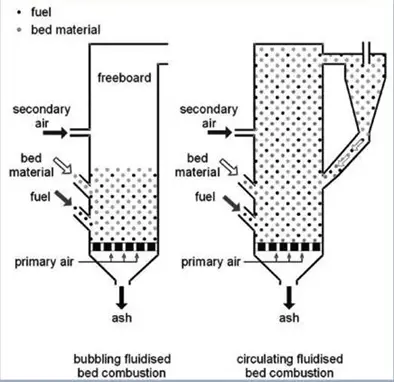
Fluidized bed gasification can be either a circulating or bubbling bed.
Fig. 1: Bubbling and circulating fluidized bed gasifier
There are several commercially available circulating fluidized bed (CFB) gasification technologies.
Initially for coal gasification, and later for biomass gasification, the U-Gas technology was designed. This gasification technology consists of a single-stage circulating fluidized bed, which was designed to process all ranges of coal and provide medium-low calorific value syngas.
For feedstocks from waste, bubbling fluidized bed technologies have been developed, and it is this technology that is the focus of this article.
The bed is heated by direct injection of oxygen and steam. Thus, the gasifier receives the feed (biomass) and gasifies it using oxygen and superheated steam. In addition, it is heated using a high-temperature flue gas passing through tubes inserted in the gasifier, thus indirectly providing heat to the process. This provides better temperature control. It also improves the control of the syngas composition.
This indirect heating is not implemented by all bubbling fluidized bed gasification technologies, but they simply inject oxygen and steam into the bed.
Feeding
Biomass and waste are potential fuel sources for gasification. However, their heterogeneous nature means that their composition is characterized as containing both combustible and non-combustible materials.
Therefore, for many gasification technologies, waste must be pre-treated to form a fuel to specification.
Pretreatment generally involves the removal of components such as glass, metals, or concrete. To reduce operating costs, the moisture content must be reduced, and the waste homogenized.
The behaviour of the main compounds involved
Pressure
The effects of pressure change are not as important as other parameters.
Methanization and methane reforming are the only reactions that are significantly affected by an increase in pressure. This makes the product gas richer in methane. Tar formation is also favoured by increased pressure. On the other hand, H2 and CO concentrations are reduced.
While the objective of combustion is to produce as much heat as possible by oxidizing all the combustible material, the objective of gasification is to convert most of the combustible solids into gases such as hydrogen, carbon monoxide, and methane.
Temperature
In general, higher temperatures enhance gasification reactions. There are different temperature ranges for different compounds:
CH4 concentration increases when the gasification temperature varies from 660 to 800 °C, while a decrease in its concentration is observed from 800 °C onwards. The initial increase in temperature can be explained by the fact that temperature favours the dealkylation of tars and the cracking of hydrocarbons to methane.
With increasing temperature, methane shifts towards H2 and CO due to the exothermic nature of the methanation reaction.
With a constant oxygen stream, the H2 content increases throughout the logical range. The H2/CO ratio undergoes a strong variation at low temperatures.
CO and CO2 concentrations show opposite trends. In the range from about 600 to 750 °C, the CO2 concentration increases slightly. In this range, CO increases rapidly.
Oxygen
Oxygen, and thus the equivalent ratio (ER), has a clear effect on the temperature and, to a lesser extent, on the syngas yield.
The gas yield increases linearly in the common range of gasification.
In contrast, tar and coal yields decrease with increasing ER. An increase in ER implies a greater amount of available oxygen and thus a greater extent of partial oxidation reactions.
The hydrogen content starts to decrease as the equivalence ratio increases above certain amounts. In this case, the H2 concentration decreases as the amount of O2 increases above a certain limit.
Similarly, the concentration of CH4 decreases under the same conditions.
Evolution of HCN, NH3, and H2S in the synthesis gas (vs. T)
The contaminants considered for a general analysis are NH3, HCN, and H2S.
The main component at low temperatures is NH3. The effect of gasification temperature (from 600°C to 800°C) shows the decrease of NH3 and H2S, while the concentration of HCN increases to a lesser extent.
These compounds have been selected to follow the evolution of nitrogen in the gas phase, as they have been identified as the main gaseous nitrogen compounds in the pyrolysis and gasification processes.
Feed nitrogen is converted to ammonia (NH3), hydrogen cyanide (HCN), and nitrogen oxides (NO, NO2, N2O, and other NOx), as well as to its stable form of N2.
NH3 is the most abundant and depends on the nitrogen content of the feedstock. As the temperature increases without additional oxygen supply, the ammonia concentration decreases and N2 becomes the predominant compound.
In the whole gasification range, HCN appears in a much lower concentration compared to NH3. The HCN concentration remains at an almost stable level, while the amount of NH3 decreases in the same temperature range.
H2S is identified as the main sulphur compound in the syngas, although it also appears to a lesser extent in the form of COS and CS2.
Under gasification conditions, the release of sulphur in the synthesis gas then occurs as H2S, while the other sulphur compounds, including also thiophenes, appear in concentrations about 20 times lower.
H2S undergoes evolution in its concentration in the temperature range. At temperatures of 600-850, the amount of hydrogen sulphide decreases, reaching a minimum at this temperature. Once 850°C is reached, H2S tends to increase its concentration again.
As for the effect of temperature, organic sulphur in biomass is generally released at low temperatures during the volatilization stage. On the other hand, inorganic sulphates show higher stability, remaining in the solid coal unless high temperatures are reached and gasification/combustion reactions of the coal occur to a greater extent.
In addition to sulphur release from the fuel, the effect of temperature on H2S release could also be related to the presence of some elements in the fuel ash (mainly Ca and K).
In the study performed by Berrueco et al., 2015, the evolution of HCl, HCN, NH3, and H2S in the produced gas is studied. The analysis was performed using ion-selective electrodes after retaining the ions in specific solutions.
In the whole range studied, HCN appeared in a higher concentration compared to NH3.
The difference from the above, as indicated in the same study, may be due to the mechanisms of the formation of nitrogenous compounds during pyrolysis.
Although the mechanisms of formation of nitrogenous compounds during gasification are still not well understood, especially in the case of biofuels, several studies give an idea of the reasons for the variation of these different studies. Factors affecting fuel-N conversion are fuel type, nitrogen functionality, initial oxygen concentration, reactor temperature, residence time, heating rate, and particle size or bed material, among others.
The study points out that the main nitrogen-containing pyrolysis product will be HCN when the nitrogen fuel is present in pyrrole and pyridinic forms, while NH3 will appear when the fuel nitrogen is present in amino groups.
This fact would explain the higher level of NH3 detected during biomass and municipal solid waste gasification.
In addition, other authors hypothesize that NH3 formation takes place mainly in thermal cracking reactions of coal, and would be favoured at low temperatures, low heating rates, and large particle sizes. This argument explains the decrease in NH3 formation concerning temperature in the present study.
On the other hand, these studies also describe the evolution of the nitrogen present in the fuel concerning the increase in temperature, showing a significant increase in the conversion to HCN.
Finally, H2S is identified as the main sulphur compound in the synthesis gas. The evolution of the hydrogen sulphide concentration in the syngas experiences a general increase in the range of 700-850 °C, with a minimum of around 750 °C.
Moisture in the inlet stream vs composition
A decrease in carbon monoxide is observed for an increase in the amount of moisture.
On the other hand, H2 and CH4 compositions are known to vary slightly, not greatly affecting the final syngas content.
Steam
The steam flow, which acts as a fluidizing agent, is adjusted.
The composition hardly varies. This is one reason why steam is used as a fluidizing agent. In this way, steam becomes a variable with which to control parameters such as fluidization rate, control the bed temperature by supplementing with oxygen, or adjust the gas velocity. The behaviour of steam in the system is detailed below.
The steam is therefore adjusted to achieve the desired fluidization velocity.
Additionally, the oxygen flow would be adjusted to match the MSW feed rate. The bed temperature is adjusted as needed.
The fluidization state of the reactor bed is defined as the ratio of the gas surface velocity to the minimum fluidization velocity. The fluidization state together with the particle diameter defines the different fluidization regimes.
The influence of a variation in the fluidization state translates into the influence that a variation of the surface velocity in the gasifying agent exerts on the process. The influence can be related to the existing gas-solid contact, the presence and formation of bubbles, the turbulence present, and the residence time of the gas in the gasifier. An increase in the value of the fluidization state causes a decrease in the residence time of the different components in the reaction zone. A consequence of this behaviour is a decrease in carbon conversion.
Once the temperature has been selected, it is necessary to control it. The main variables that influence the temperature value are the calorific value of the fuel and the amount of oxidizing agent and steam used. Steam acts as a temperature moderator and its feed temperature must be above the saturation temperature at the gasifier pressure to avoid condensation. Therefore, the steam is generally injected superheated to about 300-400 ºC and at a pressure slightly higher than the operating pressure. In addition to this steam, an inert gas such as nitrogen or carbon dioxide can also be used.
The carbon content of the inlet stream
As the carbon content increases, the H2 content decreases, as does the steam content.
Conversely, the CH4, CO2, and CO content increases.
It should be noted that if the carbon content increases, the oxygen content may be decreasing. Therefore, to maintain a constant temperature, more heat or oxygen must be supplied to the reactor.
Therefore, there is a decrease in temperature.
A correct integration involves an increase in the oxygen stream injected into the reactor, considering that more carbon has to react.
Conclusion
To achieve more excellent syngas production from waste, further development of the technologies described above is desirable to improve efficiency and reduce costs.
On the one hand, gasifying with direct oxygen and steam injection has several advantages over other gasifying agents, as described above. Through oxygen injection, a higher calorific value is achieved, and the gas produced contains fewer pollutants, in addition to improving the combustion reactions in gasification. Therefore, the cost attributed to reactor preheating is lower. Steam, on the other hand, improves the reforming reactions so that higher concentrations of H2 and CO are achieved.
However, this technology may require a steam generation plant, which may require more energy and therefore raise costs. Oxygen supply is also an aspect to be considered in the economic model.
Therefore, other technologies are also developed in which the heat in the reactor is supplied by high-temperature combustion gases passing through tubes inserted in the gasifier (Shahabuddin et al., 2020).
The residue is fed from the lower sidewall, which reacts with the superheated steam supplied from the bottom of the gasifier. The main advantages of this gasifier are the high quality of the syngas due to indirect heating and the easy control of the H2/CO ratio by adjusting the main parameters.
The most important feature of both technologies is the downstream stage of the reactor. A cyclone separator is installed at the top of the gasifier to separate the particles from the syngas. In this way, the unreacted carbon is separated from the mainstream, together with part of the ash and inerts, and transported to another reactor, where partial oxidation takes place.
The resulting synthesis gas is sent to downstream treatment units to produce various high-value products for industry.
Structural steels are produced and fabricated into various different shapes to provide support to plants, buildings, or other structures. Engineers and builders widely use structural steel shapes to make their designs strong and distribute weight to ensure integrity, safety, and durability. In this article, we will learn about various structural steel shapes that are widely used in engineering design for the construction of any building or plant.
Structural steel shapes are produced from a precise cross-section following some standards to have a definite chemical composition and mechanical properties. The shapes and dimensions of structural steel vary with respect to countries.
Major applications of structural steel shapes are found in the construction industry. Other applications are found in the automotive, transportation, mining, marine, shipbuilding, energy, packaging, and agriculture industries. It is so widely used that structural steel is known as the fundamental component of construction.
What Is Structural Steel?
Structural Steel can be defined as a high-utility ferrous material in the form of elongated beams, piping, or channels. In general, they are made from a versatile type of carbon steel grade (rolled steel). The use of structural steel is found in all engineering aspects ranging from bridges to residential and commercial constructions, from parking garages to machine bases, and various chemical, petrochemical, steel, nuclear, food, pharmaceutical, and power plants. Even though the structural steel sections are produced from Steel, various different types of metals can be used to produce shapes similar to structural steel shapes. ASTM A36 is one of the most popular structural steel materials.
The Benefits of Structural Steel
Structural steel provides a multitude of advantages in engineering. Some of the important benefits of using structural steel are:
Structural steel is cost-effective as compared to other available options. Overall costs including material, fabrication, and erection are considerably lower.
Working with structural steel is quite easy and possible even in adverse weather conditions.
Existing structural steel members can be easily recycled and reused.
Easy fabrication.
High strength and ductility, Good strength-to-weight ratio.
High load-bearing capability.
High reliability.
Easy availability.
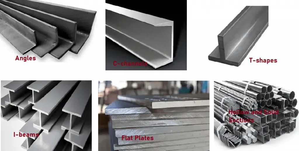
Structural Steel Shapes
Broadly, structural steel is categorized into five types of structural steel shapes: angles, beams, channels, tubing, and plates. Each of these structural steel shapes has defining features and optimal applications.
Angles
Structural steel angles are the most basic form of structural steel. It is a hot-rolled product having an L-shaped cross-section (usually 900 angles). A standard structural angle is measured by the length of the legs and the leg thickness.
L-shapes
L-shapes are structural steel angles that are produced with both equal and unequal leg lengths. Angles or L-shapes usually have limited strength. They are denoted by mentioning the longer leg first, and the thickness last.
Applications of angles and L-shapes include minor structural reinforcement, framing, shelving, brackets, and repair.
Hollow Structural Sections or Structural Steel Tubing Shapes
Hollow structural section (HSS) refers to high-strength welded steel tubing or hollow steel sections. They have round, square, elliptical, or rectangular cross-sections. Hollow structural steel shapes are usually preferred to support multidirectional loads.
Tubes are often distinguished as either mechanical or structural tubing. In low-stress applications, mechanical tubing is preferred and they have a thinner wall. On the contrary, structural tubing is used in high-stress structural applications like buildings, bridges, roll cages, and underwater platforms. The walls of hollow structural tubing sections are thicker and stronger.
Note that pipes that carry fluids are different from tubings. A pipe is designated by its nominal diameter and schedule devised by the American Standards Association.
Fig. 1: Various Structural Steel Shapes
Structural Steel Beams
Structural steel beams are the most widely used structural steel shapes. They are the major elements for supporting heavy loads and are designed to carry a maximum bending load with minimum material.
Beams are manufactured with a flat top and bottom, known as flanges. Often these flanges taper and they resist bending. The vertical section of the structural beam that connects the flanges is called the web which resists blunt force. The angle which connects the web to the flanges is called the fillet. Structural Beams are usually available in lengths up to 60 ft.
Beams are identified by their depth from the top to the bottom; flange width, flange thickness; and web thickness. Structural Steel beams can be of various types as listed below:
I-beams: I-beams are also known as universal beams or wide flange beams. The name is given as this structural shape has a cross-section that resembles the letter I with legs parallel. In any construction framework, I-beams act as critical support trusses. Click here to learn the differences between H-beam and I-beam.
S-beams: S Beams provide superior strength and have wider flanges with a slope on the inside surface. They find application in home and building construction, truck bed frames, hoists, lifts, and more.
T-beams: As the name suggests, T-beams have a T-shape. They are similar to a universal beam but without a bottom flange. T-beams are mostly used for reinforcement purposes.
Bearing Piles: Similar to I-beams, Bearing piles have a uniform thickness throughout all sections and are mainly used to support vertical loads.
H-piles: H-piles have the same I-shape but are mainly used to provide deep foundation support for superstructures.
Channels
Structural Steel channels have a C-shaped cross-section. They are found in various construction and manufacturing applications. structural channels are identified by channel depth, the top to bottom distance, leg height, leg thickness, and web thickness. To get maximum contact area, they are mounted on flat surfaces. Sometimes two C-sections are welded together to form a non-standard I-beam.
C-channels: C-channels are structural channels with a slight slope on the inner flange surface. In general, they are not used as primary load-bearing beams but they are good as frames and for bracing. Channels come in a number of shapes and are known as standard channels, MC channels, bar, and junior channels. Channels are usually available in lengths of up to 20 and 40 ft.
Plates
Structural Steel Plates are simple flat plates with the required thickness to meet various construction needs. Structural steel plate members are usually welded to build the framework for buildings and bridges.
Custom Structural Steel Shapes
Depending on project needs, many a time some specific design is produced in the steel fabrication shops and known as customized structural steel shapes. They do not fall into the standard structural shapes mentioned above. Solely based on requirements custom structural steel shapes are designed and produced.
Even though the shapes of the structural steel members are similar, they vary in dimensions and weight from region to region. Different counties have their own standards and the structural steel shapes are produced following the regional standards. The weight and dimension of structural steel shapes produced based on European standards are quite different from the similar structural shapes produced by American or Indian standards. However, when there is a mix of different standards, somewhat equivalent structural sections are used.
How to Calculate Weight of a Steel Plate? Steel Plate Weight Calculator
Many a time we need to know the weight of a steel plate we are using. In general, for billing and procurement purposes, the weight of the steel part must be known. Most of the engineering steel products like pipes, plates, etc are sold in the market with respect to weight only. So, the calculation of steel plates or other products is very important. In this article, we will learn one of the basic formulas to calculate the steel plate weight manually so that we can easily prepare a steel plate weight calculator easily.
Parameters Affecting Steel Plate Weight
To calculate the weight of a steel plate, we have to know some of the parameters that affect the weight calculation. Before proceeding with the actual equation for calculating steel plate weight, let’s understand those parameters first.
For the calculation of steel plate weight, we need to know the following two pieces of information:
Material Density
Material Dimension (Length, width, and thickness)
Material Density
The weight of any product varies proportionately with respect to its density which means products with higher density will have more weight as compared to products with lower density. Here as we are talking about steel plates we have to know the density of the specific type of steel material.
Normally, Carbon steel has a density of 7850 Kg/m3 and stainless steel has a density of 8000 Kg/m3. These densities can vary depending on exact material grades and temperature. So, to calculate the steel plate weight of a specific grade, we have to find the density of that specific steel plate material.
The densities of a specific grade of material are usually available in the ASTM standards and Specific design codes. Alternately, you can approach the manufacturer to get the densities of their produced material.
Material Dimensions (Length, width, and thickness)
The length, width, and thickness of the steel plate are required to calculate the volume of the plate. All dimensions must be in a consistent unit to calculate the volume.
Formula for Calculating the Weight of Steel Plate
Once, the material density (D) and the plate length (L), Width (B), and Thickness (T) are known we can use the following formula to calculate the weight of the steel plate (W):
Weight of Steel plate =Density of the plate X Volume of the plate
W=D * (L*B*T)
Here for the metric unit
W is in Kg
D is in Kg/m3
L, B, and T each are in m.
Calculating the Weight of Carbon Steel Plate
The weight of carbon steel plate=Length * Width * Thickness * Density Let’s assume a carbon steel plate has a length of 10 m, a width of 4 m, and a thickness of 10 mm. So, considering the density of the carbon steel plate as 7850 Kg/m3, the weight of the plate= 104(10/1000)*7850=3140 Kg. In a similar way, we can calculate the weight of all other grades of carbon steel plates.
Note that, the actual metal weight while purchasing may vary significantly from the calculated weight as there will be variations of tolerance and composition during manufacturing.
Calculating the Weight of Stainless Steel Plate
In a similar way, to calculate the weight of SS or DSS plates you gave to know the dimensions and densities of the specific grade. Then multiply those in the consistent unit following the formula mentioned above and calculate the plate weight.
The same philosophy and equation can be used to calculate the weight of any plate. If the thickness of the plates varies then calculate the weight of each part and then finally add all to get the overall plate weight.
Steel Plate Weight Calculator
So, using the above formula you can easily prepare your own steel plate weight calculator in excel sheet, visual basic, or any other program. Also, you can get various online steel plate weight calculators for getting ready-made rough weights.
Structural steel fabrication is a critical aspect of modern construction, playing an essential role in the creation of buildings, bridges, and various other structures. This article will delve into the intricate steps involved in the structural steel fabrication process, explore the materials and techniques used, and highlight the importance of quality control and safety standards in the industry.
1. What is Structural Steel?
Structural steel refers to steel shapes, plates, or bars that are engineered for use in construction. It is fabricated to specific sizes and shapes, which provide the necessary strength and support for structures. Common shapes include beams, columns, angles, and channels.
1.1 Importance of Steel in Construction
Steel is renowned for its high strength-to-weight ratio, durability, and flexibility, making it ideal for various construction applications. Its versatility allows architects and engineers to design innovative and complex structures that would be challenging to achieve with other materials. Additionally, steel is recyclable, contributing to sustainable building practices.
2. What is Structural Steel Fabrication?
Structural steel fabrication is a multifaceted process of cutting, bending, and assembling steel for the purpose of creating the final structural products. In the fabrication process of steel structures, several pieces of steel members of various forms are put together following engineering design drawings and assembled to form different structures of predefined shapes and sizes. The steel structural process is quite complex involving skilled manpower. Fabricated steel structures are found everywhere including in buildings, industrial equipment, tools, the construction industry, and various other final products.
However, note that structural steel fabrication doesn’t mean all the weldings that are performed for strengthening or repairing steel. Steel fabrication is a highly specialized skill requiring wide experience and understanding to convert raw steel components into final useful products satisfying the requirements of various codes and standards.
3. Stages of Structural Steel Fabrication
The major stages that are involved in the structural steel fabrication process are:
3.1 Design and Planning
The first stage of structural steel fabrication involves thorough design and planning. Architects and engineers collaborate to create detailed drawings and specifications for the structure. This phase includes:
Structural Analysis: Determining the loads the structure must withstand.
Drafting: Creating detailed plans and blueprints, often using software like AutoCAD or BIM (Building Information Modeling).
Material Estimates: Calculating the quantity and type of steel required.
3.2 Material Selection
Once the design is finalized, selecting the appropriate steel grade and type is crucial. Factors influencing this choice include:
Load Requirements: Different grades of steel can handle varying levels of stress.
Environmental Conditions: Corrosive environments may require weather-resistant steel.
Cost: Budget constraints may influence material selection.
3.3 Structural Steel Cutting and Shaping
3.3.1 Cutting of Structural Steel
First, the product drawing is received from the design team. It is read thoroughly to understand and find out the required steel members. Next, the structural steel fabricators cut the steel using methods like shearing, sawing, chiseling, plasma cutting, water jet cutting, or laser cutting. The steel structural fabrication process is done in a closed manufacturing facility involving abundant safety measures.
3.3.2 Bending Structural Steel
The bending of structural steel is performed by fabricators either by hammering or using machines. Machines are used when the number of repetitive bending on the project is large.
3.4 Assembling Structural Steel
In this stage of the structural steel fabrication process, steel elements are combined together to give it a final shape. This mostly involves welding and bolting. Assembled parts are quality-checked at this stage.
Welding is a critical process in structural steel fabrication, providing the strength necessary to hold the structure together. Types of welding commonly used include:
Shielded Metal Arc Welding (SMAW): Also known as stick welding.
Gas Metal Arc Welding (GMAW): Commonly referred to as MIG welding.
Gas Tungsten Arc Welding (GTAW): Also known as TIG welding.
3.5 Cleaning the surface and Blasting
In the next step, the structure surface is cleaned of the unnecessary elements stuck over the surface during cutting, bending, welding, or other steps. Several cleaning methods like surface rusting, blasting machine treatment, etc are used to clean the surface and make it ready for painting.
3.6 Painting the Steel Structure
Painting is the last stage of the structural steel fabrication process. Anti-rust paints are used to resist corrosion from environmental impacts. The steel structures are generally painted with 1 layer of anti-rust paint and 2 layers of normal paint or coating. The coating sometimes is used to resist fires.
Various design software packages have been used in recent times to supervise the steel fabrication process. Steel structures are usually produced in the facility and finally assembled at the construction site.
4. Reason for Fabricating Structural Steel
Fabrication of structural steel provides multi-dimensional benefits in construction and other projects. Some of the advantages are:
Affordability: Compared to other available metallic options, steel is stronger and quite cheaper. Hence, steel provides more value in the fabrication industry.
Prefabrication Ability: Prefabrication reduces the amount of required work to be done on-site. Structural steel is easily prefabricated and carried to the construction site for final assembly. For fast-tracking projects, prefabrication saves a lot of construction time.
Low Maintenance: Steel requires less maintenance as compared to its other counterparts. Also, the steel provides easy repairability and long-lasting capabilities.
Appearance: Steel provides an enhanced appearance to projects regardless of the look required.
Environmental: As steel can be endlessly reused and recycled, it is environmentally friendly. Steel production requires less energy and generates less carbon dioxide.
Strength: Structural steel is one of the strongest metals and weighs up to a third less than comparable metals. It is highly durable.
Malleable: Structural steel is malleable and can be formed into any complex shape to meet project requirements. Also, structural steel, being an alloy, the properties can be adjusted as required.
Structural steel is coated with fire-resistant materials to make it highly resistant to fire. It is water-resistant. When designed and built properly, It can withstand storms and earthquakes.
5. Uses of Structural Steel Fabrication
The modern age can not be thought of without structural steel. Structural steel fabrication is used in all industries like construction, manufacturing, automotive, shipbuilding, and other industries. Some of the applications of structural steel fabrication are listed below:
Manufacturing Industries: The manufacturing industry uses structural steel to produce industrial stairs, platforms, steel ladders, mezzanines, steel handrails, and more.
Construction Industries: Steel beams, steel plates, girders, steel sections of various shapes (H, I, L, Angle, Plate), etc form parts of a large group of fabricated steel structures in the construction industry.
Energy Industry: The energy industries highly rely on fabricated structural steel. Transmission towers, pipelines, wind turbines, oil and gas well platforms, nuclear plants, etc all use various structural steel fabrication methods.
Mining Industry: Structural steel fabrication is part of the mining infrastructure. Various structural steel sections like fittings, pipes, grating, rods, beams, rails, etc are widely used in the mining industry.
Shipbuilding Industry: The shipbuilding industry is heavily reliant on structural steel fabrication for its parts like ferries, recreational boats, and supertankers.
Aerospace Industry: To manufacture various aircraft parts, Structural steel is essential.
Automotive industry: Automotive engines and various safety features use structural steel fabrication in the automotive industry.
7. Tools and Equipment for Structural Steel Fabrication
7.1 Cutting Tools
Various tools are employed for cutting steel, including:
Band Saws: For straight cuts.
Plasma Cutters: For complex shapes.
Laser Cutters: For precision work.
7.2 Welding Equipment
The choice of welding equipment can impact the quality of the final product. Common tools include:
MIG Welders: Ideal for quick welds.
TIG Welders: For high-quality, clean welds.
7.3 Inspection Tools
Ensuring the integrity of the steel is paramount, and inspection tools include:
Ultrasonic Testing Equipment: For detecting internal flaws.
Magnetic Particle Testing: To identify surface cracks.
8. Quality Control in Steel Fabrication
8.1 Importance of Quality Control
Quality control ensures that the fabricated steel meets design specifications and industry standards. It minimizes risks associated with structural failures and enhances safety.
8.2 Standards and Certifications
Several organizations set standards for structural steel fabrication, including:
American Institute of Steel Construction (AISC): Provides guidelines for steel structures.
American Welding Society (AWS): Establishes welding standards.
9. Safety Standards in Steel Fabrication
9.1 Workplace Safety
Safety is paramount in the fabrication industry. Essential practices include:
Personal Protective Equipment (PPE): Hard hats, gloves, and goggles.
Safety Training: Regular training for employees on safe practices.
9.2 Environmental Considerations
Environmental concerns are increasingly relevant in steel fabrication. Practices include:
Waste Management: Proper disposal of scrap metal.
Pollution Control: Minimizing emissions from welding and cutting processes.
The structural steel fabrication process is a complex and essential part of modern construction. Understanding each step, from design to installation, highlights the importance of precision, quality control, and safety.