Pressure Safety Valves (PSV) or Pressure Relief Valves (PRV) are important instruments used to protect enclosed equipment or vessels from over-pressure scenarios. When the system pressure exceeds a certain limit (set pressure), the PSV/PRV pops up and vents out the overpressurized fluid to control the overpressure situation. In the oil & gas, power generation, steel manufacturing, chemical/plastics industries, water/wastewater, and aerospace/aviation industries PSV/PRV systems are widely used to protect people, property, and the process.
A PSV is a final link in the safety chain and these must work properly to safeguard the system. To ensure that the PSV will work smoothly and open when the need arises, they must be tested. In this article, we will explore the PSV testing requirements, procedures, and standards.
Requirements for PSV/PRV Testing
The PSV/PRV that is installed at the operating plant must be tested frequently based on the inspection plan or manufacturer’s guidelines to be assured that the intended operation will be successful when the need arises. Every PSV is usually tested every 1-3 years to find out that the mechanical parts are not stock closed, not worn due to corrosion, and valve seats are intact.
Types of PSV Testing
Depending on the location where the PSV testing will be performed there are two types of PSV testing procedures.
In-situ or Online PSV Testing and
Bench PSV Testing
Online PSV Testing
Online PSV testing is performed at the operating plant at their operating temperature and pressure condition. This is the most cost-effective PSV testing process as the plant remains operational. But the main difficulty with In-site PSV testing is reaching the set pressure.
Bench Testing of PSV/PRV
To avoid the set pressure challenge, the entire PSV is removed from the operating system and then taken to the lab for bench testing. This method is costly and time-consuming. Also, the PSV line remains in shut down condition till the PSV is tested and returned back to the line. However, many operating plants keep an extra PSV for keeping the plant operational during this time.
PSV Testing Procedure
The PSV testing is also known as Popping Test or Cracking Test. The test must be performed by an expert technician. The main elements required for the test are:
the PSV/PRV under test
a reference pressure gauge
an external pressure source.
The PSV testing process is performed as per the following steps.
Step 1: Check the PSV set pressure engraved on the riveted tag. Theoretically, the PSV should pop open when the system pressure reaches this value.
Step 2: Install the calibrated and certified pressure gauge to measure the pressure. Always ensure that the gauge has sufficient range to measure that pressure.
Step 3: Keep increasing the PSV inlet side pressure from the external pressure source until the PSV pops up with a sudden releasing sound. Note the pressure gauge reading at that instant.
Step 4: Now slowly decrease the pressure and note the pressure when the PSV closes (Reseat in position).
Step 5: Repeat the PSV testing process at least 3 times and record the pressures each time for confirmation.
Step 6: Send the readings to the certifying authority for certification and approval.
While performing the PSV test procedure, the following parameters need to be closely monitored:
The valve should open up at the set pressure of the PSV.
For the overpressure scenario, the discharge fluid rate shall be as per the PSV datasheet.
The valve should seat in position and close tightly when the pressure is lowered.
Codes and Standards for PSV Testing
The following codes and standards are generally followed for PSV testing guidelines:
ASME Sec VIII
API 520
API RP 527
API RP 521
API 581
API RP 576
ASME PTC 25
BS EN ISO 4126-1, 4126-2, and 4126-3
NZA 3788
PSV Testing Results: Pass/Fail Criteria
The results of a PSV/PRV testing process can be classified as passed, failed safe, or failed to danger.
A PSV test result will be termed as PASS when all the following criteria are satisfied:
The PSV pops up within +/-3% of its set pressure.
The valve reseats with +2.5% to -7% of the set pressure.
There are no visible leaks during the test
A PSV test result will be termed as failed safe when
The initial POP test lifts within a range of 103 to 110% or less than 97% of the set pressure.
The seat tightness is more than the limits specified in API 527.
A PSV test result will be termed as failed to danger when any of the following occurs:
If the relieving pressure is more than 110% of the set pressure.
If damage is found in its components like spring, bellows, leaking pilot diaphragm, blockage or leakage of the impulse and sensing line.
What are Pickling and Passivation? Their Meaning, Procedure, Advantages, and Differences
Pickling and Passivation are chemical processes used in the metal industry to protect metals from corrosion. Both pickling and passivation are widely used for stainless steel products. Some acidic chemicals are used over the stainless steel to create a passive layer or to remove contaminants. In this article, we will explore more about the pickling and passivation process. Let’s start with the definition of both processes.
What is Pickling?
Pickling is basically a metal cleaning process. In the pickling process, thin layers of metal (in form of stains, inorganic contaminants, foreign matter, grease, oil, rust or scale, etc) are removed from the surface of stainless steel. For the pickling of stainless steel, usually, a mixture of nitric and hydrofluoric acid is used.
Pickling is a popular process for removing weld heat-tinted layers from stainless steel surfaces. However, the Pickling process causes etching of the surface and affects the surface finish making it dull.
What is Passivation?
Passivation is a chemical treatment process where the stainless steel is treated with an oxidizing acid. Passivation dissolves carbon steel, and sulfide inclusions and removes iron and other surface contaminants from the stainless steel surface. At the same time, the acid promotes a chromium-rich thin but dense passive film (oxide protective layer) formation. This passive film imparts corrosion resistance quality.
Passivation of stainless steel is performed using nitric acid. Similar to pickled steel, passivated steel does not affect the metal’s appearance.
Advantages of Pickling and Passivation Process
The processes of pickling and passivating steel offer various advantages to the metal products like:
Both pickling and passivation remove surface impurities and contamination generated during manufacturing and fabrication.
Increase the durability and longevity of the stainless steel products with reduced corrosion possibility.
Weld hint tint or weld discoloration is removed and the metal looks smooth without imperfections.
Chemical film barrier against rust.
Reduced need for maintenance.
Pickling and Passivation Procedure
Pickling Process:
A range of methods can be applied to the pickling process. The most popular methods are:
Tank Immersion Pickling– Can be done on-site or off-site. Provides a facility for treating all the fabrication surfaces at the same time. This achieves uniformity of surface finish and optimum corrosion resistance.
Circulation Pickling– This type of pickling method is recommended for piping systems carrying corrosive fluids. In this pickling process, the chemical solution is circulated through a system of pipework.
Spray Pickling– Spray pickling is done for on-site treatment. Proper acid disposal and safety procedures must be ensured during the spray pickling process.
Gel Pickling– This is a manual pickling operation in which gels are applied on metal surfaces by brushing. It pickling method is quite useful for the spot treatment of welds and other intricate areas that require manual detail.
Passivation Process:
The passivation of stainless steel is performed using weak acids like nitric acid or citric acid. The main aim of passivation treatment is the formation of a passive layer that does not easily interact with the environment. Before the acid passivation process, the surfaces must be cleaned to make them free from oxide scales, oils, grease, and other lubricant, heat tints must be removed. After that nitric acid chemical/paste is applied to the material surface.
Passivation is a post-fabrication process used for newly fabricated stainless steel parts. The effect of passivation was first discovered by chemist Christian Friedrich Schönbein in the mid-1800s. However, the process of passivation become widely useful in the 1900s.
The weak nitric or citric acid chemically dissolves the free iron present on the surface. The chromium remains intact which creates a chromium oxide layer upon exposure to oxygen over the next 24 to 48 hours. This passive layer provides a chemically non-reactive surface.
Please note that passivation is not an electrolytic process, this is not a process to remove scale, and It does not change the surface color or appearance. The steps followed for the passivation process are:
Alkaline cleaning of the metal surface.
Deionized (DI) Water rinse
Nitric or Citric acid immersion bath
DI Water rinse
Drying of the part
Testing the effectiveness of the process.
Codes and Standards for Pickling and Passivation
Widely used codes and standards that govern the pickling and passivation process are:
ASTM A380
ASTM A967
ISO 16048
AMS 2700
ASTM B600
AMS-STD-753
BS (British Standard) EN 2516
The treatment duration for pickling and passivation treatment normally varies from 5 minutes to 45 minutes. The oxide layer left by passivation is roughly .0000001 inch thick.
Pickling vs Passivation: Differences
Both pickling and passivation are chemical surface treatment processes and are widely used for stainless steel. However, there are some differences between the processes in terms of the intensity of the treatments. The major differences between the pickling and passivation processes are tabulated below:
Pickling
Passivation
Acids used in the pickling process are more aggressive
Passivation uses weak acids (either citric acid or nitric acid).
Pickling makes greater changes to the surface
Passivation only creates a thin surface layer and does not change material properties.
The pickling process removes metal impurities on a sub-level basis.
Passivation normally does not remove metal impurities or contamination. It mainly makes the surface passive to corrosion.
Pickling vs Passivation
What is a Foot Valve? It’s Working, Types, and Applications: Foot Valve vs Check Valve
A foot valve is a special type of non-return valve, with a strainer affixed to the open end. For suction lift applications, foot valves are widely used in the pump suction or at the bottom of pipelines. The use of foot valves, keeps the pump primed, the fluid flows in but does not flow back out, and hence they are ideal for wells, ponds, and pools. As the flow area of the foot valves is larger than the pipe size, there is very less head loss.
Working of a Foot Valve
Foot valves being unidirectional allow the flow only in one direction and the valve closes for reverse flow. The inlet strainer of the foot valve filters out the unnecessary solid particles from the fluid and thus prevents valve damage.
When pumps are used to move fluids from lower to higher elevations, a lot of energy will be required. At the same time when the pump is turned off, the liquid will flow back to the lower level. But the use of foot valves prevents this reverse flow. The foot valve maintains the liquid column even when the pump is not working.
Foot valves are basically a type of check valve that prevents the backflow of liquid. They are placed in the pick-up end of the pipe and are located at the very bottom. When the pump is started, a suction is created which opens the foot valve. Water or other liquid easily enters the pipe through the foot valve due to the pulling force of the pump. But when the pump is turned off, this pulling force is removed but still, the water level retains its level as the foot valve does not allow the water to flow back. thus the pump remains always primed.
Requirements for Foot Valves
Foot valves are used for various reasons like:
To keep the pump primed when pumping liquid from lower to higher levels.
To prevent damage to water pumps without foot valves there may be dry runs. Without a foot valve, the air will fill the pipe which will oppose the water flow and the pump will run dry.
To reduce energy wastage.
Functions of the Strainer for the Foot Valve
The strainer in a foot valve filters out the debris that may jam the foot valve and can cause damage to the pump. So, the strainers protect the valves and pumps and perform a very important function.
Features of a Foot Valve
Foot valves usually have self-tapping male and female threads that help in easy installation. They have internal balls for quick sealing and valve reaction. They are flexible enough to fit various types of water pump uses. Foot valves are cheaper compared to other valves.
Components of Foot Valves
Each foot valve consists of 4 basic components:
Screen: To remove sediments or debris.
Body: The complete mechanism is housed within the valve body.
Seat: The seat is an integral part of the body and uses o-rings to avoid leakage when the valve is closed. The valve lands on the seat when the pump is turned off.
Disc: This is the gateway of the foot valve. When the disc is raised, liquid can enter.
Materials for Foot Valves
Foot valves are usually constructed of heavy-duty cast iron, bronze, Stainless Steel, PVC, and Plastic. Foot valves are normally used for water services and these materials last longer when submerged in water.
Applications of Foot Valves
As foot valves prevent the suction column from draining when the pump is not in operation, they are widely used in all kinds of pneumatic systems. The major application of foot valves is found in pumps and because of that, they are sometimes called foot valves for pumps or well-pump foot valves. Typical applications of foot valves include:
Suction lines of the pipeline
Ponds, pools, and wells, where pumps are used to transfer water.
Sump pumps, and intake pumps, in rivers and lakes.
Foot valves can be classified based on construction and flow systems. Based on the construction of foot valves, there are two types of foot valves, Membrane foot valve, and ball foot valve.
Membrane foot valve: In a membrane foot valve, a cylindrical rubber membrane is fitted inside a steel strainer. When the suction is formed in the strainer, the membrane is displaced and the liquid flows through the valve. The cylindrical membrane closes during a reverse flow and thus prevents the backflow.
Ball foot valve: In this type of foot valve, a cylindrical inclined chamber and seating have used that guide the ball valve. When inward flow occurs, the ball is displaced with its chamber, and fluid flows. On the other hand, when the flow rate decreases, it runs down the chamber onto its seat and the valve prevents reverse flow. Ball foot valves are mostly used for contaminated water.
According to the flow system, the foot valves are classified as Microflow system valves, high-flow system valves, and low-flow system valves.
The microflow system valves are mostly made of stainless steel and used in direct push technology micro-wells and multilevel good installation.
The high-flow system valves are used on 2-inch wells or larger and can stand high pumping rates and very deep wells.
The low-flow system valves are used in small diameter piezometers which lift up to 100 feet of water.
Based on the types of threads used, foot valves are of three types:
Female threaded foot valve.
Male threaded foot valve
Dual-threaded foot valve
Selection of Foot Valves
Foot valves are selected considering various parameters like:
The task that the foot valve will perform and fluid service.
Duty of valve; whether heavy-duty or light-duty.
Load the foot valve need to carry.
Durability.
Maintaining a Foot Valve
Even though a foot valve is a small element, it must be properly maintained. Some of the steps that can be followed to increase the life of foot valves are:
Regular cleaning of debris of the foot valve.
Regular checking of corrosion signs.
Ensuring that the tank or well bottom is clean
Difference between Foot Valve and Check Valve
Even though both the check valve and foot valve serves a similar function of a non-return valve i.e, preventing backflow, there are some distinct differences between the two valves. They are:
3D models are very popular in the engineering of process and power piping industries as they graphically represent the overall plant with all equipment, piping, structures, instruments, and electrical connections in a three-dimensional view. These 3D models are close to the real plant that will be built at the site after construction. Various 3-D piping design software packages like PDMS, SP3D, E3D, etc simulate the actual plant in the 3D model that gives a better representation of the plant as compared to the age-old 2D plant models. They are the electronic equivalents of real plants. In this article, we will explore the 3D model review procedures.
What is a 3D Model Review?
A 3D model review is a design procedure to present the electronic 3D model to the client to verify that the current stage of the design meets the minimum project requirements for operability, maintainability, constructability, safety, and functionality and that it reflects every discipline’s input to the design to date. All discipline engineers review the 3D model through a walkthrough of the plant. Any design changes required are discussed and listed as Model review comments which will be taken care of after the model review.
For small projects for which 3D software packages are not used a similar philosophy of review termed Desktop Review is followed.
Stages of 3D Model Review
3D Model review, in general, is performed in three stages; 30% model review, 60% model review, and 90% model review. The percentage term used along with model review denoted the percentage completion of the design stage. These model reviews are major checkpoints and milestones in the engineering design process. Deliverables required from each discipline to achieve each of these checkpoints are defined in the model review matrix.
Typically a model review will not proceed until such time that all of the deliverables required for the specific review have been incorporated. When deliverables are missing for a particular review, the model review may only proceed provided that the associated risks and mitigations have been identified and approved by the project manager.
30% Model Review
A 30% model review means the design is complete by roughly 30% and is the 1st milestone for model preparation. All design data is not yet firm at this stage. This phase aims to lay out the major design elements of the project. It establishes the cost and timeline of the project. 30% model review generates a basis for plant layout, accessibility, and safety measures recommendation. Only the large-diameter critical lines are routed and modeled. At the 30% model review stage, the contractor and client meet to set a basis for further development of the design.
The 30% model review phase is the foundation of the project. From this point onwards the design will be developed further continuously.
Objectives of 30% model review
The 30% 3D model review is performed to serve the following objectives:
To discuss and agree on overall plant layout qualifying hazard recommendations and other project requirements.
To fix the equipment location considering the available information.
To identify primary operational/assessable/maintenance points or platforms.
To identify improvements considering the safety and operation aspects.
To release foundation loads for structural design.
To finalize the equipment nozzle orientation and send the information to the vendor.
To finalize the main underground isometrics for fabrication.
Important points that are usually included and discussed during any model review are usually decided by the model review matrix. The model review matrix outlines the preparedness required by each discipline at each stage of the design review and the items to be reviewed at that stage. A sample model review matrix explaining the piping items is provided in Table 1 below.
60% Model Review is the second milestone of the model review process and serves the utmost importance of the project. All the doubts raised during the 30% model review are clarified during this phase. In this stage, the team focuses more on the analysis of constructability, budget consideration, modification, and potential issues or concerns. The model review team discusses the constructability of the drawings and any preferred equipment and material needed to build the project during this stage.
60% model review phase is also considered to be a good time for value engineering. Any changes or modifications after a 60% model review will significantly impact the schedule, cost, and overall design. In general, the 60 % model review is carried out and closed out prior to issuing the piping isometrics for construction.
Objectives of 60% model review
The main objectives of the 60% model review process are:
To check if the design is at par with the safety philosophies and requirements.
To determine the location of secondary fire/safety equipment
To find out if the main equipment locations are in order and updated.
To review the location of minor equipment.
To review the secondary operability/accessibility/maintainability as required.
To review and release buried isometrics for IFC.
To release the updated nozzle orientation information to the vendor.
90% model Review
This is the final model review and the design is almost final with all data and information. 90% model review finalizes the total design of the model. All the comments from the 60% model review stage are resolved and incorporated into the 90% model review. All drawings and specifications are ready with the design team for issue as final. 90% model review is the last stage for the client to suggest any minor changes. The construction schedule, phasing plan, logistics plan, etc are finalized at this stage.
During the 90% model review stage, the model must be substantially complete, including instrumentation and all Manufacturer/Supplier information, to allow final comments to be made.
Objectives of 90% model review
The main objectives of the 90% model are:
To ensure that the final design is acceptable to the client and agree to IFC issues of all drawings and specifications.
To ensure that operational and maintenance access has been provided to all required items.
To ensure the construction feasibility of all plant components.
To ensure all safety philosophies and recommendations are implemented prior to the publication of drawings.
To ensure the model reflects all project requirements.
3D Model Review Responsibility
3D Model Review is the joint responsibility of the piping lead, the designer/drafter, the project engineer, and other related disciplines. The piping engineer and the project engineer are the primary organizers of the model review. In most cases, the piping leads show the plant by walk-through of the complete plant. All comments are recorded in a proper project format for resolution and incorporation. Any necessary changes and comments are agreed upon and immediately recorded and marked with reference numbers and model pictures to allow follow-up and avoid misunderstanding.
The main responsibilities of the primary organizers are as follows:
Responsibilities of the project engineer:
Project engineers
Decides the required attendees, and schedules and manages the formal model reviews.
Ensures that the design progress meets the requirements for the review as defined in the model review matrix.
Prepares and issues an agenda for the review.
Coordinates the discussions and documents resolutions and action items.
Ensures proper filing of all documentation.
Distributes the model review comments to the attendees.
Responsibilities of the piping lead:
The piping lead engineer
Coordinates with CAD support for the assembly of the 3-D models required for the review.
Operates or designates a team member to operate the computer “walk-through” during the review.
Ensures that an interference check has been completed prior to the review.
Ensure that a “snapshot in time” of the 3-D model files used for the review is archived for future reference and record-keeping after each review.
Captures all comments/action items in the software package.
Maintains a hard copy binder and logs and distributes the action items to the designers.
The important activities and responsibilities can be listed as follows:
Schedule for model review: Project Manager
Model review document preparation: Project Engineer
Distribution of review document and agenda to the client: Project engineer
Organize model review venue: Project engineer
Review tools and create a model file: Design Administrator
Report status of 3D CAD model: Lead piping engineers
Report of hold item list: Lead piping engineers
Coordination during model review meeting: Project engineer
Preparation and Summarize of the action list: Project engineer
Review, reconciliation, and distribution of action list report: Project manager
Follow up and Updation on Action list: Project engineer/Lead piping engineer
Review model and Status files: Design Administrator
Supporting Documents and Drawings for Model Review
Various documents may be required during the actual model review process. Hence the following documents with their latest approved revision should be made available during the model review session. These drawings are usually marked as “Model Review master“. These important documents and drawings are:
For each model review session, the contractor notifies the client and all other disciplines about the venue and time of each model review session. Usually, the following professionals participate in the model review session:
Instrument/Electrical engineer: As per requirement
Structural Engineer: As per the requirement
Safety Engineer: Full time
HVAC: As per requirement
Civil Engineer: On-call
3D Model Review Checklist
Checklists of 3D model reviews are prepared to ensure that important checkpoints are discussed and not missed during the session. The 3D model review checklist varies with the stages of the model review. Some typical points that are included in the 3D model review checklists are listed below:
30% Model Review Checklist
The 30% model review checklist usually considers the following checkpoints:
Location of all equipment and their orientation
Major critical piping routes
Separation distance within plots
Constructability
Drainage philosophy
Access to major valves
As-built coordinates of tie-ins with existing pipe or equipment.
Major wall and floor penetrations.
Equipment status
60% Model Review Checklist
The 60% model review checklist emphasizes the following major points:
Pressure regulators play a critical role in ensuring the safe and efficient operation of equipment and processes in the oil and gas industry. From drilling to refining, maintaining optimal pressure levels is essential for the smooth functioning of systems that involve the handling of volatile substances.
What Are Pressure Regulators?
A pressure regulator is a device designed to maintain a desired output pressure by controlling the flow of gas or liquid from a high-pressure source to a lower-pressure environment. It automatically adjusts the pressure to the required level, ensuring consistent performance of the downstream equipment.
In the oil and gas industry, pressure regulators are used extensively to manage the pressure in pipelines, storage tanks, and processing equipment to ensure safety, reduce risks, and improve efficiency.
Pressure regulators are devices used for controlling fluid pressures within a range. The main function of a pressure regulator is to reduce a high input pressure to control lower output pressure. Pressure regulators can even find applications in situations where constant output pressure is required to be maintained.
The Role of Pressure Regulators in Oil and Gas Operations
Oil and gas extraction, processing, and transportation involve highly pressurized fluids and gases, making pressure regulation essential at various stages. Below are some key areas where pressure regulators are indispensable:
Drilling Operations: During the drilling phase, pressure regulators are used to control the flow of drilling mud and prevent blowouts. This ensures that the well remains under control even in high-pressure reservoirs.
Gas Distribution: In natural gas distribution systems, pressure regulators manage the flow of gas from high-pressure pipelines to lower-pressure delivery systems that supply consumers.
Processing and Refining: Refineries use pressure regulators to maintain the optimal pressure within reactors, distillation columns, and other equipment. Proper pressure regulation ensures that chemical reactions occur efficiently and that safety is maintained in case of overpressure.
Pipeline Transportation: Long-distance transportation of oil and gas requires precise pressure control to minimize energy loss and ensure the integrity of pipelines. Regulators help manage pressure drops across pipelines and maintain steady flow rates.
Storage: Pressure regulators control the pressure inside storage tanks, especially when storing liquefied natural gas (LNG) or other compressed gases. This prevents hazardous conditions, such as over-pressurization, which could lead to explosions.
Other applications of pressure regulators are:
gas grills,
heating furnaces,
dental equipment,
pneumatic automation systems,
automotive engines,
aerospace applications,
hydrogen fuel cells,
reclaim driving helmets
pressure cookers and pressure vessels,
welding and cutting,
gas-powered vehicles,
mining and natural gas industries,
hyperbaric chambers,
inflating tires, etc
Functions of a Pressure Regulator
As already stated the main purpose of installing a pressure regulator is to reduce the pressure. However, they can effectively be used to perform the following functions:
Regulating the back-pressure
As pressure switching valves in pneumatic logic systems.
As vacuum regulators, to maintain a constant vacuum.
Components of a Pressure Regulator
All pressure regulators are characterized by the reduction of the inlet pressure to lower output pressure. There are three main components that help a pressure regulator perform its intended function are:
A loading element like an actuator or spring to apply the required force
A sensing element like a piston or diaphragm.
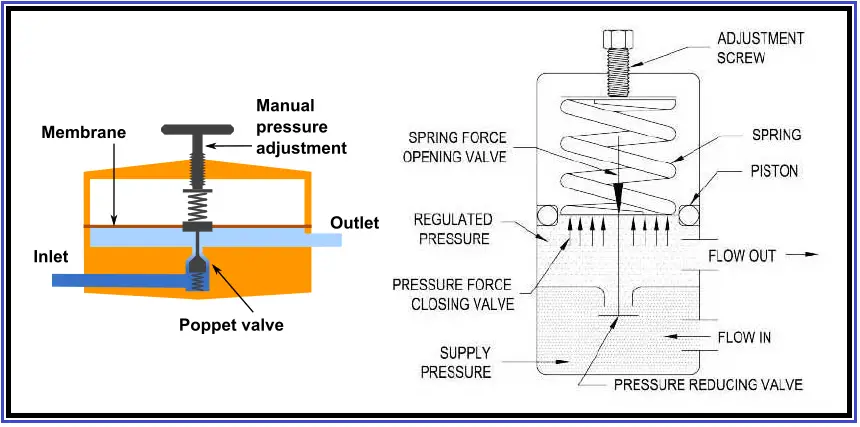
Refer to Fig. 1 below which shows the schematic diagram of a typical pressure regulator.
Fig. 1: Schematic of a Typical Pressure Regulator
The pressure-reducing valve is also known as the restricting element. It provides a variable restriction to the flow. Examples include a globe valve, butterfly valve, poppet valve, etc.
The loading element is a part that can apply the needed force to the pressure-reducing valve. A weight, a spring, the diaphragm actuator in combination with a spring, or a piston actuator can act as the loading element.
The measuring element or sensing element determines when the inlet flow is equal to the outlet flow. Often, the diaphragm itself works as a measuring element; it can serve as a combined element.
Types of Pressure Regulators
Depending on the number of stages employed to get the final reduced pressure, there are three types of pressure regulators.
Single-Stage Pressure Regulator: For relatively small pressure reduction in the range of 100 to 150 psi. Used for machine tools, test stands, linear actuators, automated machinery, leak test equipment, etc.
Dual Stage Pressure Regulator (Suitable for large variations in the inlet pressure), and
Three-Stage Pressure Regulator: They provide a stable outlet pressure and are able to handle larger pressure reduction. Typical examples are UAVs, medical devices, analytical instruments, hydrogen fuel cells, etc.
Again, based on the working methods they can be broadly categorized into the following two classes.
Self-operated Pressure Regulator: Simplest design. They have greater accuracy at lower pressures and lower accuracy at higher pressures. They do not require external sensing lines for effective operation.
Pilot Operated Pressure Regulators: They are complex in design but can handle larger pressure fluctuations. Pilot-operated pressure regulators provide precise control of pressure.
Based on the application of pressure regulators they are sometimes termed as:
Water pressure regulator
Gas pressure regulator
Fuel pressure regulator
Working of Pressure Regulators
A pressure regulator matches the gas flow through the regulator to the gas demand placed upon it. At the same time, they maintain a sufficiently constant output pressure. When the load flow decreases, the regulator flow also decreases. Again, when the load flow increases, then the regulator flow also increases and thus keeps the controlled pressure from decreasing due to a shortage of gas in the pressure system. The pressure regulators are so designed that the controlled pressure does not vary greatly from the set point for a wide range of flow rates. At the same time, the flow through the regulator is stable and the regulated pressure is not subject to excessive oscillation.
Pressure Regulator Materials
The material of pressure regulators varies depending on the operating environment and compatibility of the fluid handled. Common materials that are used in typical pressure regulators are:
Brass
Aluminum
Stainless Steel
Plastic
Stainless Steel and sometimes carbon steel are used for spring materials. Seal material is usually Fluorocarbon, EPDM, Perfluoroelastomer, or Silicone.
Selection of Pressure Regulators
Even though pressure regulators are found in various sizes and constructions, Some parameters must be considered for proper selection. Common parameters that influence the selection process of pressure regulators are:
Operating temperature and pressure range (Both inlet and outlet temperature and pressure)
Fluid service medium and properties (Gas or liquid, Corrosive or Non-corrosive, Hazardous or Non-toxic, Explosive nature, etc)
Capacity or flow required (Maximum, minimum, and flow variation)
Material requirements
Accuracy required
Connection Size
Dimension, weight, and size
Installing Pressure Regulators
Installation of pressure regulators must be performed considering manufacturer guidelines. In general, the following steps are followed for pressure regulator installation:
Step 1: Connect the pressure source to the inlet port and the reduced pressure line to the outlet port. These ports are usually marked, else contact the manufacturer.
Step 2: Turn on the supply pressure gradually to avoid any shock.
Step 3: Set the regulator at the desired outlet pressure. Slight adjustments can be done to get the desired pressure.
Pressure regulators are fundamental to the safe and efficient operation of oil and gas systems. From wellheads to refineries, these devices help control the flow of gases and liquids, protect equipment, and ensure worker safety. By selecting the right type of pressure regulator and maintaining it properly, oil and gas companies can optimize their processes, reduce risks, and comply with environmental and safety regulations.
What is a Shut-Off Valve? It’s Working, Function, Types, and Selection
A shut-off valve is a valve that safely manages the flow of hazardous fluids (liquids, gases, slurries, and fluidized solids). Shut-off valves are also known as on-off valves, cut-off valves, lockout valves, stop valves, etc. They safely stop or continue the fluid flow. When not in use they isolate the sub-system.
Shut-off valves belong to a large family of valves. Various types of valves like ball valves, globe valves, gate valves, pressure valves, temperature control valves, solenoid valves, instrument valves, etc may work as a shutoff valves. Shut-off valves are widely used where system safety is of importance as they represent a positive action safety device. Some examples of shut-off valve applications are:
Air preparation unit.
Industrial Automation Process.
Fuel units
Pneumatic industry.
Water Industry
Working of Shut off Valves
Each shut-off valve consists of two fundamental components.
The valve body through which the fuel, liquid, slurry, or gaseous fluids pass and
The control device, which is equipped with a sensitive element.
The control element ensures the required closing and opening of the valve. When everything works correctly, the fluid passes through the valve smoothly. However, when any anomaly (for example excessive fluid expansion, breakage of capillary, etc) arises the control device closes the flow passage inside the valve.
Selection of a Shut-off Valve
Based on the application there are various types of shut-off valves. So, the selection of the appropriate shut-off valve is not easy. Various parameters need to be considered while selecting the shut-off valve for a specific service and operation. The important factors to consider are:
Type of application
Size and weight
Temperature and Pressure
Range
Working Environment
Port size, position, and type
Types of Shut-off Valves
Shutoff valves are categorized based on various parameters like working, configuration, application, etc. Depending on the turning of the handle there are two types of shut-off valves;
Multi-turn shut-off valve and
Quarter-turn shut-off valve
Depending on configuration shut-off valve types are:
Straight shutoff valve
Angle shut-off valve
Again, depending on the applications they are popularly categorized as
Water shut-off valve
Gas shut-off valve
Fuel shut-off valve, etc
Various materials are used to manufacture shut-off valves based on fluid service compatibility. Common shut-off valve materials are Brass, Carbon Steel, Stainless Steel, Alloy Steel, etc. For low-pressure temperature applications in the water industry plastic or polypropylene, valves are used.
Functions of a Shut-off Valve
All shut-off valves are designed to provide fully on or fully off functionality. So they function similarly to an electric switch, either stopping the flow completely or allowing it fully.
Shut off Valve Symbols
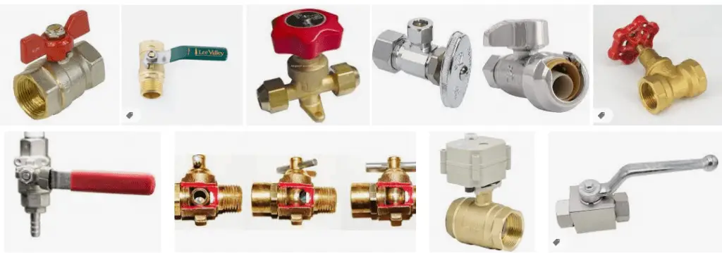
All valves are indicated in P&ID and isometric with specific symbols. Shut-off valves also have their symbols. The symbols of shut-off valves are decided based on the specific valve type used as a shut-off valve. So, the shut-off valve symbols differ from ball valve to angle valve or globe valve.
Fig. 1 below shows some typical images of shut-off valves.