Pressure drop is a widely used term that is frequently used in design engineering, process industries, etc. So it is very important to have a thorough knowledge of pressure drop. Pressure drop is the difference in pressure between two points provided that there is a fluid flow between those points. So pressure drop occurs when a fluid (gas/liquid) material enters one point of the piping system and exits through the other points. In that case, process piping systems should have losses of pressure, and this phenomenon is known as pressure drop.
Pressure drop occurs due to friction caused by fluids rubbing against the pipe surface and the internal walls of a pipeline.
For a system, pressure drop can be calculated with engineering equations that require the type of fluid, flow rate, fluid properties, plot plan, and piping material specifications (including thickness, schedule number, and pipe diameter).
Why does Pressure Drop important?
If the pressure drop in a system is high then the process fluid temperature rises, and energy consumption will be high. Overall system pressure also increases for the high-pressure drop. The high-pressure drop also increases wear on components and causes potentially dangerous & over-pressure scenarios. Lastly, a large pressure drop may render some piping component systems disable due to insufficient operating pressure.
Process engineers should have a clear understanding of the pressure drop of the whole network associated with a fluid to be handled so that they can determine the size, capacity of the pump and motors, and piping diameter required to carry the specific fluid through the piping system.
The larger the pressure drops in the pipeline, the larger the energy required to retain the required process flow, requiring a higher horsepower motor. On the other hand, for low, pressure drop in a pipeline, less energy is required, providing the potential to use a smaller hp motor. Pressure drop also governs the overall pressure of the system or head requirements.
What is a Pressure Head?
In short, the pressure head is defined as the height (m/ft) to which a selected pump can bring a column of water that is usually expressed in meters.
It is the magnitude of the force the pump exerts on the fluid that is being pumped. From the Pump vendor, data pressure heads may be available or they can be calculated from the formula.
What factors affect the Pressure Drop?
The following factors affect the pressure drop in a fluid-carrying network,
Fluid Component
Various fluid parameters like Density, Heat capacity, Temperature, and Viscosity affect the pressure drop of the fluid.
Some products change their viscosity drastically while being pumped through a pipeline due to shear. These kinds of products will become due to frictional effects caused by the passing through the pumps and the internal surfaces of the pipes. This type of fluid is called the thixotropic fluid which is a time-dependent fluid. Thixotropic fluids are usually viscous fluids in stagnant conditions. But it gets thinner or low viscous during movement while shaking or mixing & it returns to its normal state while the means of mixing is removed.
On the other hand, some others are called Newtonian fluids under certain processing conditions. Newtonian fluids are not thixotropic fluid, and it is not subjected to vary their viscosities upon exposure to shear force. Fluids that show Newtonian characteristics may add to higher pressure drop while being pumped through a piping system because their viscosity will not vary as it passes through the system.
Mechanical Component
The mechanical elements in a piping system that imparts pressure drops are valves, strainers, flow meters, couplings, fittings, bends, and tubing. Excluding pumps, all of these other elements commonly available in a process piping system contribute to an overall pressure drop of the system as they remove pressure energy from the process fluid, rather than adding to it.
This dynamic pressure drop depends on the cross-sectional area of the piping system as well as an internal surface roughness (roughness factor), the equivalent length of the pipeline.
Changes in Elevation
Changes in elevation in the Piping system significantly affect the pressure drop. The additional pressure drop will occur if the starting elevation of a pipe is lower than its end elevation. This elevation difference is measured in the fluid industry in terms of the fluid head.
For a general piping system, the overall pressure drop is usually calculated using equations similar to the following:
P(end)= P(start) – friction loss- fittings loss -component loss + elevation (start-end) + pump head
Pressure Drop Equations/ Pressure Drop Calculation
Due to different elevations, turbulence caused by changes in flow direction and frictional losses while flowing through piping and losses due to fittings pressure drop or head loss is caused. The widely used methods used to calculate the head loss in glass pipe are Manning, Darcy-Weisbach, and Hazen-Williams, equations. The applicability of each method governs by the flow pattern (gravity flow or pumped flow).
Hazen-Williams Equation
The Hazen-Williams equation is normally used for water pipes while the flow is fully turbulent flow. It has achieved a wide range of acceptance in the water and wastewater industries as it is very simple to use. The equation is as follows,
V=0.85 C R0.63 J0.54
where
v = velocity, m/s
C = Hazen-Williams Coefficient
R = Hydraulic mean radius, m
J = Hydraulic gradient, m/m
Hazen-William coefficient, C for ADPF fiberglass pipe is taken as 150.
Manning Equation
For gravity difference flow, the Manning equation typically is used to solve gravity flow problems where the flow partially fills the pipe under the influence of changes in elevation. The equation is as follows,
V= (1/n) R0.667J0.5
where
v = velocity, m/s
n = Manning’s Coefficient
R = Hydraulic mean radius, m
J = Hydraulic gradient, m/m
Manning’s Coefficient, n for ADPF fiberglass pipe is taken as 0.01.
Darcy-Weisbach Equation
This equation states that pressure drop is directly proportional to the square of the velocity and the length of the pipe. This equation is applicable for all fluids for both laminar as well as turbulent flow. The disadvantage of this equation is that the Darcy-Weisbach friction factor is a variable that can be found in the standard chart available. The equation is as follows,
The table given below determines the type of flow of fluid from the Reynolds number.
Type of Flow
Reynolds Number
Laminar Flow
Re≤2200
Transition Flow Zone
2200≤Re≤4000
Turbulent Flow
Re≥4000
Types of Fluids as per Reynold’s Number
If the flow is Laminar, f = 64 / Re If the flow is Turbulent, the friction factor can be determined from the Moody diagram found in most fluid mechanics texts or calculated from the Colebrook equation.
1/√f=-2Log(ε/3.71D+2.51/(Re√f))
where
ε = Roughness.
Re = Reynolds number
The Colebrook correlation friction factor for fiberglass pipe is determined as 0.04 mm which includes the head losses over joints.
Pressure drops in Pipe Fittings
Head Loss or pressure drop in Pipe fitting is usually defined as the equivalent length of pipe that is added to the straight run of pipe. This approach is mostly associated with the Hazen-Williams or Manning’s equations. This method does not consider the effect due to turbulence and subsequent losses caused by different velocities.
Equivalent Length (in m)
Pipe Fittings
150
200
250
300
350
400
450
500
600
700
800
900
1000
90ᵒElbow
8.5
6.4
7.9
9.4
10.7
12.2
14.0
17.0
23.0
28.0
32.4
37.1
42.3
45ᵒElbow
3.5
3.4
4.2
5.0
5.7
6.5
8.2
10.9
13.6
16.2
20.1
23.5
25.6
Tee
11.0
14.4
17.8
21.1
24.0
27.5
32.8
38.3
49.5
61.5
72.9
84.6
96.8
Equivalent Length for Pipe Fittings in m
For a more accurate calculation, head loss in fittings can be determined using loss coefficients (K-factor) for each type of bend & fittings. In this method, K-factor is multiplied by the velocity head of the fluid flowing through the bends and fittings.
The relevant equation is H=K x (V2/2g).
where,
H = Head loss, m
V = Velocity of flow, m/s
K-Factors for Pipe Fittings
Type of Pipe fittings
K-Factor
90ᵒElbow, standard
0.5
90ᵒElbow, single miter
1.4
90ᵒElbow, double miter
0.8
90ᵒElbow, triple miter
0.8
45ᵒElbow, standard
0.3
45ᵒElbow, single miter
0.5
Tee, flow to branch
1.4
Tee, flow from branch
1.7
Reducer, single reduction
0.7
K-factors for various Pipe Fittings
Water Hammer
It is caused due to pressure surge or internal shock, resulting from a sudden change of velocity within the system. As a result, these shock waves can reach a sufficient level to rupture or collapse a piping system irrespective of the material of construction. The surge pressure is the faster moving wave that increases as well as decreases the pressure in the piping system that depends on the source of the direction of the shock wave travels. Fast valve closure can result in the building-up of shock waves as the kinetic energy of the faster-moving fluid is converted to the potential energy that must be accommodated. These pressure waves traverse throughout the whole piping system and may cause mechanical damage far away from the source of the shock wave.
The effect of the water hammer depends on,
Physical properties of the fluid
Volumetric flow rate
Elastic modulus of the pipe material
The equivalent length of the pipeline
Rate of change of momentum
The lower value of elastic modulus fiberglass generates a dampening effect as the pressure wave moves along the piping system. As the elastic modulus of piping material is very high so the pressure waves generated in the pipeline are very high in magnitude. Additionally, due to the fast closure and opening of the valve, sudden air release, and start-up or shut down of the pump can cause water hammer.
Talbot formula gives:
P= (a.w.V)/(144.g)=(a/g).(SG/2.3).V
where,
a=Wave velocity (ft/s)
P = Surge Pressure (psi)
v = fluid velocity (ft/s)
w = Density of fluid (lb/ft³)
SG = Specific gravity of the fluid
K = Bulk modulus of fluid (psi)
E = Hoop modulus of elasticity (psi)
d = Inside diameter of the pipe (inch)
t = Pipe wall thickness (inch)
g = Acceleration due to gravity (ft/s²)
How to prevent water hammer?
Standard design practices can avoid water hammers in most systems.
Rapid opening and closing of valves are to be avoided.
The Greenhouse Effect and the concept of achieving Net-zero Carbon Emissions are critical topics in the context of climate change and environmental sustainability. In this comprehensive explanation, I’ll provide detailed insights into both these subjects to equip you with a thorough understanding.
The greenhouse effect is a natural phenomenon that warms the Earth’s surface. It occurs when the sun’s energy reaches the Earth, and some of that energy is reflected back to space while the rest is absorbed and re-radiated by greenhouse gases. This process is crucial for maintaining the temperatures necessary for life on our planet. However, human activities are amplifying this effect, leading to climate change and a host of environmental challenges.
What is the Greenhouse Effect?
Warming of the Earth’s surface and troposphere (the lowest layer of the atmosphere) in the presence of water vapor, carbon dioxide, methane, and other specific gases in the air is called the greenhouse effect. Of these gases known as greenhouse gases, water vapor has the greatest impact. The atmosphere penetrates most of the sun’s visible light and reaches the surface of the earth. Since the surface of the earth is heated by sunlight, part of its energy is radiated into space as infrared rays.
Unlike visible light, this radiation is absorbed by greenhouse gases in the atmosphere and raises their temperature. The heated atmosphere then radiates infrared rays to the surface of the earth. Without greenhouse warming, the average surface temperature of the Earth would be only about -18 ° C (0 ° F). On Venus, the concentration of carbon dioxide in the atmosphere is so high that it has a very high greenhouse effect, with surface temperatures up to 450 °C (840 °F).
The greenhouse effect is a naturally occurring phenomenon, but its effects can be amplified by the release of greenhouse gases into the atmosphere as a result of human activity. From the beginning of the Industrial Revolution to the end of the 20th century, the carbon dioxide content in the atmosphere increased by about 30% and the methane content more than doubled. This global warming can change the Earth’s climate, create new patterns and extreme droughts and rainfall, and disrupt food production in certain regions.
Greenhouse Effect
Mechanism of greenhouse effect
So, the mechanism of the greenhouse effect can be summarized as follows:
Solar Radiation:
The Earth receives energy from the sun in the form of solar radiation. Approximately 30% of this radiation is reflected back to space by clouds, atmospheric particles, and reflective surfaces (like ice and snow). The remaining 70% is absorbed by the Earth’s surface and oceans.
Infrared Radiation:
As the Earth absorbs solar energy, it warms up and re-emits this energy in the form of infrared radiation. This radiation is then either absorbed by greenhouse gases or escapes into space.
Heat Trapping:
Greenhouse gases absorb and re-radiate the infrared radiation, trapping heat in the atmosphere. This process keeps the Earth’s surface significantly warmer than it would be otherwise—approximately 33 degrees Celsius (59 degrees Fahrenheit) warmer.
What are greenhouse gases?
Greenhouse gases (also called GHGs) are gases in the Earth’s atmosphere that trap heat. During the day, the sun shines through the atmosphere, warming the surface of the earth. At night, the earth’s surface cools and radiates heat into the atmosphere. Part of the heat is however trapped by greenhouse gases present in the atmosphere. Greenhouse gases on Earth trap heat in the atmosphere and warm the Earth. The main gases responsible for the greenhouse effect include carbon dioxide, methane, nitrous oxide, water vapor (all of which are naturally occurring), and fluorinated gases.
Carbon Dioxide (CO2): Released from various natural processes like volcanic eruptions and human activities such as burning fossil fuels and deforestation.
Methane (CH4): Emitted during processes like enteric fermentation in livestock, rice cultivation, and the production and transport of fossil fuels.
Water Vapor (H2O): The most abundant greenhouse gas, its concentration varies greatly with location and climate.
Nitrous Oxide (N₂O): Emitted during agricultural and industrial activities, as well as during the combustion of fossil fuels and solid waste.
Why is it called greenhouse gas?
Greenhouse gases are so named because they absorb infrared rays from the sun in the form of heat, which circulates in the atmosphere and eventually is lost to space.
Greenhouse gases in the atmosphere act like a blanket around the Earth. When the Earth’s surface emits infrared radiation, greenhouse gases absorb some of this heat energy, preventing it from escaping directly into space. Instead, they re-radiate the heat energy in all directions, including back toward the Earth’s surface.
This process of re-radiation effectively traps heat energy in the Earth’s atmosphere, warming the planet. Without this natural Greenhouse Effect, the Earth’s average temperature would be significantly colder, making it inhospitable for most forms of life.
Why CO2 is a greenhouse gas?
Carbon dioxide molecules in the atmosphere absorb far-infrared energy (heat) from the earth and then re-emit it, and some of it returns. This effectively traps the heat around the earth. Carbon dioxide (CO2) is one of several greenhouse gases in the atmosphere.
What are greenhouse gases made of?
Greenhouse gases are water vapor, methane, ozone, nitrous oxide, and carbon dioxide. Some of these gases may not be very present in our atmosphere, but they can have a significant impact. Each greenhouse gas molecule is composed of three or more loosely bonded atoms.
Is ozone a greenhouse gas?
Ozone is technically a greenhouse gas, but it can be useful or harmful depending on where it is in the Earth’s atmosphere.
Is H2 a greenhouse gas?
H2 is an indirect greenhouse gas that reacts with other greenhouse gases in the atmosphere to increase its Global Warming Potential (GWP).
The Importance of the Greenhouse Effect
Natural Regulation of Climate
The greenhouse effect plays a vital role in regulating the Earth’s climate. Without it, the average surface temperature would be about -18 degrees Celsius (0 degrees Fahrenheit), making life as we know it impossible. This natural warming allows for liquid water to exist on the planet, which is essential for all known forms of life.
Biodiversity and Ecosystems
A stable climate facilitated by the greenhouse effect supports diverse ecosystems. Plants, animals, and microorganisms all rely on specific temperature ranges and weather patterns to thrive. Disruptions to this balance can lead to biodiversity loss, habitat destruction, and extinction events.
Enhanced Greenhouse Effect
Human Impact on the Greenhouse Effect
Industrial Revolution and GHG Emissions
Since the Industrial Revolution in the late 18th century, human activities have significantly increased the concentration of greenhouse gases in the atmosphere. The burning of fossil fuels for energy, transportation, and industry has led to a dramatic rise in CO₂ levels.
Deforestation
Forests act as carbon sinks, absorbing CO₂ from the atmosphere. Deforestation, whether for agriculture, logging, or urban development, reduces the planet’s capacity to sequester carbon and contributes to higher atmospheric CO₂ levels.
Agriculture and Livestock
Agricultural practices contribute significantly to methane and nitrous oxide emissions. Livestock production, rice cultivation, and the use of synthetic fertilizers are key contributors to the rise in these potent greenhouse gases.
Urbanization
The expansion of cities leads to increased energy consumption and emissions. Urban areas are often characterized by higher temperatures (urban heat islands) due to human activities and reduced vegetation.
Human activities, especially the burning of fossil fuels (coal, oil, and natural gas), deforestation, and industrial processes, have increased the concentration of greenhouse gases in the atmosphere. This enhanced Greenhouse Effect results in a stronger trapping of heat energy and leads to global warming, which is a major driver of climate change.
Consequences of the Enhanced Greenhouse Effect
The consequences of the enhanced Greenhouse Effect are numerous and severe:
Global Temperature Rise: The Earth’s average temperature has been steadily increasing due to the enhanced Greenhouse Effect, leading to phenomena like global warming.
Melting Ice and Sea Level Rise: Warming temperatures cause ice caps and glaciers to melt, contributing to rising sea levels, which can lead to coastal flooding and the displacement of communities.
Extreme Weather Events: Climate change intensifies extreme weather events such as hurricanes, droughts, heatwaves, and heavy rainfall, causing damage to ecosystems and human infrastructure.
Disruption of Ecosystems: Many species struggle to adapt to rapidly changing climates, leading to shifts in ecosystems and potential extinctions.
Ocean Acidification: Increased CO₂ levels are not only warming the planet but also leading to higher levels of dissolved CO₂ in oceans, causing ocean acidification. This affects marine life, particularly organisms with calcium carbonate shells, such as corals and shellfish.
Impact on Agriculture: Climate change affects agricultural productivity. Changes in temperature and precipitation patterns can lead to reduced crop yields, threatening food security, especially in vulnerable regions.
Mitigation Strategies
Reducing Greenhouse Gas Emissions
Transition to Renewable Energy: Shifting from fossil fuels to renewable energy sources like solar, wind, and hydroelectric power can significantly reduce CO₂ emissions.
Energy Efficiency: Improving energy efficiency in buildings, transportation, and industries can lower energy consumption and emissions.
Carbon Capture and Storage (CCS): This technology captures CO₂ emissions from sources like power plants and stores it underground, preventing it from entering the atmosphere.
Sustainable Agriculture: Adopting practices like agroforestry, organic farming, and improved livestock management can help reduce emissions from the agricultural sector.
Reforestation and Afforestation
Restoring forests and planting new trees can enhance carbon sequestration, helping to absorb CO₂ from the atmosphere. Initiatives like REDD+ (Reducing Emissions from Deforestation and Forest Degradation) aim to incentivize forest conservation.
Promoting Sustainable Transportation
Encouraging public transportation, cycling, and electric vehicles can reduce emissions from the transportation sector. Urban planning that prioritizes walkability and green spaces can also contribute to lower emissions.
Policy and Legislation
Governments play a crucial role in addressing climate change. Implementing policies like carbon pricing, emissions trading systems, and regulatory measures can incentivize emissions reductions.
Public Awareness and Education
Raising public awareness about climate change and the greenhouse effect is essential. Education can empower individuals and communities to take action, from reducing personal carbon footprints to advocating for systemic change.
The Role of International Agreements
The Paris Agreement
Adopted in 2015, the Paris Agreement aims to limit global warming to well below 2 degrees Celsius, with efforts to keep it below 1.5 degrees. Countries are required to set and communicate their nationally determined contributions (NDCs) to reduce emissions.
Other Global Initiatives
Various global initiatives, such as the Kyoto Protocol and the Sustainable Development Goals (SDGs), aim to address climate change and promote sustainable development. Collaboration among nations is crucial for effective action.
Net-zero Carbon Emission
The urgency to combat climate change has never been more pressing. With increasing global temperatures, rising sea levels, and extreme weather events becoming commonplace, the need for substantial action is clear. One of the most critical strategies in this fight is achieving net zero carbon emissions. But what does it mean to achieve net zero, and how can individuals, businesses, and governments work towards this goal?
Net-zero carbon emissions, often referred to as carbon neutrality or net-zero greenhouse gas emissions, is a critical concept and goal in addressing climate change. Achieving net-zero emissions is central to mitigating the effects of the enhanced Greenhouse Effect. Let’s delve into the details:
What does net-zero carbon emission mean?
Net zero means balancing the greenhouse gases released into the atmosphere with the greenhouse gases removed. Think of it like a bath-turn on the faucet, add more water, and pull out the stopper to let the water flow out. The amount of water in the bath depends on both the input from the faucet and the output from the drain. To keep the amount of water in the bath at the same level, it is necessary to balance the entrance and exit. Reaching net zero applies the same principles. It needs to balance the number of greenhouse gases we emit with the amount we remove. If you add only what you remove, you reach net zero. This condition is also called climate neutrality. However, zero emissions and zero carbons are slightly different because they usually mean that no emissions occur at all.
How you can make difference between gross zero and net zero?
Given the impact of carbon emissions on the planet, you may be wondering why we are not aiming for zero or gross zero instead of net zero. Gross zero means stopping all emissions, but this is not realistically achievable in all aspects of our lives and industry. Even with the best efforts to reduce them, there are still some emissions. Net zero makes it possible to look at emissions as a whole and eliminate all unavoidable emissions. From aviation or manufacturing. Greenhouse gas removal can come from nature, new technologies, or modified industrial processes, as trees absorb carbon dioxide from the atmosphere.
Why is net zero important?
Net zero is a condition in which greenhouse gases flowing into the atmosphere are offset by removal from the atmosphere. At least for CO2, the term net zero is important because this is where global warming stops. So, the main Importance of Net Zero are
Climate Stabilization: Achieving net zero is essential to limit global warming to 1.5°C above pre-industrial levels, as outlined in the Paris Agreement. This temperature threshold is crucial to avoiding catastrophic climate impacts.
Economic Opportunities: Transitioning to a net zero economy can stimulate economic growth by creating jobs in renewable energy, energy efficiency, and sustainable industries.
Public Health: Reducing carbon emissions can lead to cleaner air and water, ultimately improving public health and reducing healthcare costs associated with pollution-related diseases.
Pathways to Achieving Net-zero Carbon Emissions
Achieving net-zero carbon emissions involves a combination of strategies and actions. Here are some key components:
Reducing Emissions: The primary focus is on reducing emissions of greenhouse gases. This includes transitioning to renewable energy sources (solar, wind, hydro, etc.), improving energy efficiency, and implementing sustainable practices in various sectors like transportation, agriculture, and industry.
Carbon Offsetting: For emissions that cannot be completely eliminated, such as those from certain industrial processes or transportation, carbon offsetting is used. This involves investing in projects that remove or reduce an equivalent amount of greenhouse gases from the atmosphere, such as reforestation, afforestation, and carbon capture and storage (CCS) projects.
Technological Innovations: Developing and deploying innovative technologies like CCS, direct air capture (DAC), and low-carbon transportation options are essential for achieving net-zero emissions.
Behavioral Changes: Encouraging individuals and communities to adopt sustainable practices, such as reducing energy consumption, changing dietary habits, and using public transportation, contributes to emissions reduction.
Policy and Regulation: Governments and international bodies play a crucial role in setting policies and regulations that incentivize emissions reduction and support the transition to a low-carbon economy.
Importance of Net-zero Carbon Emissions
Achieving net-zero carbon emissions is vital for several reasons:
Mitigating Climate Change: By stabilizing the concentration of greenhouse gases in the atmosphere, we can slow down and eventually halt the progression of global warming and its associated impacts.
Preserving Ecosystems: A stable climate is crucial for preserving biodiversity and ecosystems, as many species are sensitive to changes in temperature and habitat.
Protecting Vulnerable Communities: Many communities, particularly in developing countries and coastal regions, are disproportionately affected by climate change. Achieving net-zero emissions can help protect these vulnerable populations.
Sustainable Development: The transition to a low-carbon economy can drive innovation, create jobs, and promote sustainable development while reducing reliance on finite fossil fuel resources.
Strategies for Achieving Net Zero
1. Transitioning to Renewable Energy
One of the most effective ways to achieve net zero is by transitioning from fossil fuels to renewable energy sources.
Solar Power: Harnessing sunlight to generate electricity. Technological advancements have significantly reduced costs and improved efficiency.
Wind Energy: Utilizing wind turbines to generate electricity, which has become one of the fastest-growing sources of energy.
Hydropower: Generating electricity from flowing water, though care must be taken to minimize environmental impacts.
2. Energy Efficiency
Improving energy efficiency across all sectors can drastically reduce emissions.
Buildings: Retrofitting buildings with better insulation, energy-efficient appliances, and smart technology can lower energy consumption.
Transportation: Promoting electric vehicles (EVs), improving public transportation, and encouraging non-motorized transport can reduce reliance on fossil fuels.
3. Carbon Capture and Storage (CCS)
CCS technologies capture carbon emissions from sources like power plants and store them underground to prevent them from entering the atmosphere.
4. Sustainable Agriculture
Shifting agricultural practices can significantly reduce emissions:
Regenerative Farming: Practices that enhance soil health and increase carbon sequestration.
Agroforestry: Integrating trees and shrubs into agricultural landscapes to improve biodiversity and carbon capture.
5. Afforestation and Reforestation
Planting trees and restoring forests are critical for absorbing CO2 from the atmosphere.
Urban Green Spaces: Creating parks and green roofs can also contribute to local carbon sequestration efforts.
6. Behavioral Change
Encouraging sustainable lifestyle choices can help individuals and communities reduce their carbon footprints.
Dietary Changes: Reducing meat consumption and increasing plant-based diets can lower agricultural emissions.
Waste Reduction: Minimizing waste and promoting recycling can help reduce methane emissions from landfills.
Challenges and Considerations
While the concept of net-zero carbon emissions is essential, achieving it poses several challenges:
Technological Limitations: Some technologies required for large-scale emissions reduction and removal are still in the early stages of development and may not be economically viable yet.
Behavioral Change: Convincing individuals and businesses to adopt sustainable practices and change their behavior can be challenging.
Equity and Justice: Achieving net-zero emissions must be equitable, taking into account the historical contributions of different countries and the needs of vulnerable populations.
Transitioning Energy Systems: Transitioning from fossil fuels to renewable energy sources requires significant investment and infrastructure changes.
Monitoring and Verification: Accurately measuring and verifying emissions and removals is essential for ensuring that net-zero targets are met.
What is climate change?
According to the World Meteorological Organization, the 20 hottest years on record were in the past 22 years, and the four hottest years were all very recent: from 2015 to 2018. The average global temperature is now 1℃ higher than the previous time. One degree may not seem like much, but the reality is that this gradual warming seems to be having a negative effect. Furthermore, if recent trends continue, it is expected to worsen, with global temperatures predicted to rise to 35℃ by 2100. Despite a slight increase in global temperatures, we are feeling the effects of climate change and have the following unstable weather patterns: Floods and hurricanes; polar ice loss; and sea-level rise. This is only getting worse as global warming increases.
What is causing climate change?
It is widely recognized by scientists and governments that climate change is caused by higher amounts of greenhouse gases in the atmosphere. Their name comes from the greenhouse effect they create by heating the Earth’s surface and the air above it. Carbon dioxide is the most abundant and dangerous of greenhouse gases, so reducing carbon emissions, creating a carbon footprint, or finding proposed low-carbon alternatives are ways to combat the change. climate.
How can we stop climate change?
Excess greenhouse gases in the atmosphere cause harmful global warming. Therefore, reducing the number of these gases will contribute to combating climate change. Stopping climate change can be done in two ways:
reduce the emissions we send into the atmosphere from activities such as industrial processes, power generation, transportation, and intensive agriculture
remove greenhouse gas emissions from the atmosphere, for example by capturing carbon produced in industrial processes before being released or by planting more trees.
What is green energy?
Green energy comes from natural sources like the sun and wind.
What’s the difference between renewable energy and green energy?
Renewable energy comes from sources of continuous and natural self-renewal (hence the name), such as wind power and solar energy. Renewable energy is also commonly referred to as sustainable energy. Renewable energy sources as opposed to fossil fuels, such as coal and gas, are finite sources of energy. In addition, the burning of fossil fuels to release energy is a cause of climate change.
The terms “green energy” and “renewable energy” are often used interchangeably, but there is one key and sometimes confusing difference between them. Although most green energy sources are also renewable, not all renewable energy sources are considered completely green. Take for example hydroelectricity. While hydroelectricity – the energy generated from fast-flowing water – is renewable, some argue that the process of generating large amounts of electricity from water is not green, given the associated industrialization and deforestation related to the construction of large hydroelectric dams.
What are the basic differences between green energy, clean energy, and renewable energy?
Clean energy is energy that, when used, does not pollute the atmosphere; produces little or no greenhouse gases. Again, there is a clear intersection between clean energy, green energy, and renewable
energy. Here’s a simple way to tell them apart:
Clean energy = clean air
Green energy = source from nature
Renewable energy = renewable sources
What is Smart Plant Instrumentation (SPI) Intools?
SmartPlant Instrumentation (SPI) is one of the foremost instrumentation engineering tools developed by Intergraph. Earlier, the same software was well-known as the Intools. The software acts as a single and widely used instrumentation application that is used in Engineering, Procurement, and Construction (EPC) Projects. Smart plant instrumentation helps in accessing and updating the instruments used in any plant for various tasks.
The software is used for managing and designing various activities including:
The majority of EPC firms use this instrumentation design tool. Smartplant instrumentation creates a single engineering design environment that creates and manages data required by instrumentation engineers. This software is an all-in-one solution for all Instrumentation and Process deliverables. The software package can seamlessly manage those data consistently throughout the design lifecycle.
What’s inside SPI and how does it work?
Project execution involves several tasks, to which many disciplines contribute. Executing these tasks in a systematic way makes the engineering deliverables better which will support the plant construction and operations.
SmartPlant Instrumentation is a platform that is progressing toward a module-oriented environment. This indicates this interface deals with the script at hand, for example:
Process module – Collect process data from SmartPlant P&ID. Edit information and add that data set into the instrument design basis wherever applicable.
Instrument Index module – Recall and expand the rule base instrument design basis from the P&ID into all physical instruments. This function performs as Process – Instrumentation synchronization.
Specification module – By using Engineering Data Editor create specific interfaces as well as user experiences that can be configured to perform the specific task – for example, to create instrument datasheets/specifications, which include SmartPlant Instrumentation data along with the data those are related to or coming from vendors specifications.
Wiring module – Build up the Engineering Data Editor for junction boxes, marshaling cabinet (including DCS and PLC), assigning the cable and wiring data script to auto-connect instruments with junction boxes, and junction boxes with cabinets. This task includes a loops check for connectivity. Here comes Instrumentation – Electrical synchronization.
This extended focus increased productivity and asset management quality.
How does Intergraph Data sharing work on SPI?
SmartPlant Instrumentation acts as a receiving engine from various data sources, which includes the process group, piping department, and electrical and instrumentation team. The outcome data then feeds into the piping group for the equipment or inline instruments, and interlocks for electrical, in addition to interfacing and interacting with vendor and third parties catalogs.
SmartPlant Instrumentation also supports operational activities, not only generating new and even as-built data also. SPI also offers a seamless interface for calibration with Fluke, and for maintenance scheduling interface with ERP providers such as the SAP platform.
Vendor data and catalog access are rapidly becoming more important to drive productivity and engineering design quality. Instead of finding and re-typing in SPI, you can easily access vendor data, for example, I/O card details for DCS, instruments under vendors’ scope like E+H, or valves from Rosemount/Emerson. SmartPlant Instrumentation makes it easy to get accurate data quickly.
How SmartPlant Instrumentation (SPI) contributes to the plant life cycle?
SmartPlant Instrumentation gains value for instrument-related workflow throughout the life cycle of the plant. SPI contributes to Engineering and Design, Procurement, Construction, Commissioning, Operations, and Maintenance.
Engineering and Design – SmartPlant Instrumentation helps to manage and create instrumentation data in a discrete database, which facilitates faster, synchronal engineering to reduce project manhours and cost. This software assures data accuracy, persistent deliverables, effective and optimized change management system. By creating various engineering rules this software maintains data integrity. Vast two-way integration with other software (like AutoCAD, Microstation, etc.) even with vendors (like Yokogawa, Emerson, etc.) to reduce manual entry and design time. Quality of data increases.
Procurement – Design data can easily be transferred from SmartPlant Instrumentation to Intergraph’s SmartPlant Materials, which can shorten the procurement cycle. Warehouses can easily maintain the purchase and change-over records in SmartPlant Materials, which makes procurement hassle-free.
Construction – The user can extract control panel drawing from the database. The contractor can start construction for the control panel and can modify it whenever required by simply modifying the database.
Commissioning – With the help of SmartPlant Explorer along with SmartPlant Instrumentation users can access data and test loop continuity. SmartPlant Explorer is more towards mark-up capability via the online Web.
Operations and Maintenance – SmartPlant Instrumentation along with SmartPlant P&ID acts as a single data package. The operator can easily access P&ID and instrument data simultaneously while operating the plant. These data are consistent, accurate, and current. So there is less chance of error, which makes maintenance easy.
Advantages of Smart Plant Instrumentation (SPI)
Plant engineers and operators use Smart Instrumentation Intools for asset performance management which translates to a variety of functions like power management, process automation, maintenance systems, safety, and asset optimization. The Intools software makes the sensors, electronics, and process diagnostics data to be centralized and aligned with tasks. This result in huge saving in labor hours and cost with improved compliance and consistency in managing change.
The major benefits that Smart instrumentation software packages provide are:
Reduced Risk, downtime, and increased profit.
Fully automated generation of engineering deliverables like wiring diagrams, loop diagrams, and specifications from centralized data.
Improved performance of control system and associated documents.
Rapid execution with custom design rules
Improved work efficiency
Reduced cost due to data leveraging and consistent design.
How SmartPlant Instrumentation gain value?
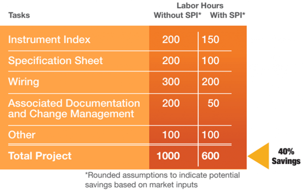
SmartPlant Instrumentation can easily facilitate small to very large projects. With a single source of all data offered, this software ensures that consistent changes are reflected, recorded, and flagged. This software platform helps to reduce project cycle manhours and gain value.
Intergraph calculated after facilitating a Large LNG project like 18 billion US$ in SmartPlant Instrumentation can save up to 40% of the project cycle manhours. Refer to the following figure
Fig. 1: Reduction in Project Man-hour Cost when using SPI Tools
What is API 5L Pipe? Its Grades, Specification, and Schedule chart
API 5L is a seamless and welded carbon steel pipe material specification. API 5L pipes are widely used to transport oil, water, and gases in the pipeline industry. Depending on the strength, schedule, and service requirements API 5L pipes are manufactured in various grades and are suitable for both onshore and offshore applications. In this article, we will learn about the various grades, specifications, and schedule charts of API 5L pipes.
API 5L pipes in the oil and gas, water, and petrochemical industries are available in two Product Specification Levels (PSL) depending on quality levels. The first one is PSL1 which provides a standard quality level. The other one PSL2 provides additional mandatory requirements in strength, chemical composition, NDT, or notch toughness.
Grades of API 5L Pipes
API 5L pipes are produced in various grades. Each API 5L grade varies in its strength capabilities. A unique alpha or alphanumeric designation is assigned to each grade of API 5l pipes. Leaving Grade A and Grade B, all other API 5l grades mention the specified minimum yield strength in their numerical portion of the designation. These yield strength values are expressed in KSI (kilopound per square inch) for the USC unit and in MPa (Mega Pascal) for the SI unit system.
The common grades of API 5L pipes that are widely used are:
API 5L Grade B (USC unit system) or L245 (SI unit system)
API 5L Grade X42 or L290
API 5L Grade X52 or L360
API 5L Grade X60 or L415
Other API 5L grades that are also manufactured for various applications are:
API 5L Grade A25 or L175
API 5L Grade A25P or L175P
API 5L Grade A or L210
API 5L Grade X46 or L320
API 5L Grade X56 or L390
API 5L Grade X65 or L450
API 5L Grade X75 or L485
Various letters have suffixed these grades to indicate special requirements like N denotes normalized, Q denotes quenched and tempered, and M denotes thermomechanical rolled or formed.
As informed earlier the numerical value denotes the specified minimum yield strength in USC or SI unit. For example, for API 5L X42 material the term 42 denoted 42KSI as the specified minimum yield strength of the material. Similarly, API 5L L360 denotes the specified minimum yield strength for the material is 360 MPa.
Purchasing Information
While purchasing the API 5L material the following details must be specified in the purchase order or material data sheet.
PSL levels (PSL1 or PSL2).
Grade of the Pipe required (Proper pipe designation).
Pipe Size, Outer diameter, and thickness.
Random or Approximate length.
Seamless or Welded.
Quantity of pipe required (Total length or Total mass).
Pipe end connection.
Coating and lining requirements.
Fluid service sour or sweet.
Any marking requirements.
Any special requirements, etc
Specification of API 5L Pipe
API 5L Pipe specification is prepared with respect to various aspects as listed below:
Standard Scope: The scope of API 5L pipe mainly includes the application of the pipe for water and oil and gas pipeline transmission.
Manufacturing types: The specification includes the manufacturing types as welded and seamless. Cast pipes are not covered in the specification.
Pipes under 24″ are usually seamless or ERW, whereas large diameter pipes are SAW/DSAW. LSAW is used up to 48″ in size whereas SSAW/HSAW can be used up to 100″ in size.
Different Grades: API 5L line pipe specification covers Gr. A, B, X42, X46, X52, X56, X60, X65, X70, X80, etc. There are various delivery conditions as required for different applications.
Material specifications (Chemical and Mechanical): The material datasheet specifies the chemical composition and mechanical properties of each grade of API 5L pipe material.
Test Methods: Hydrostatic test is the most common testing method applied for the API 5L line pipe to investigate joint leakage. Other tests include the bend test, flattening test, etc. The line pipe must be free from cracks, sweat, leaks, or any other defects.
Other important considerations are:
Tolerances on pipe diameters, wall thickness, out-of-roundness
Similar to other carbon steel pipes, the pipe thicknesses are not standardized for all API 5L pipe grades. The OD of pipes matches the OD of other carbon steel pipes. However, the thickness varies. Depending on high strength the thickness used for specific applications is usually reduced. High-strength and low-thickness pipelines are widely used in the pipeline industry.
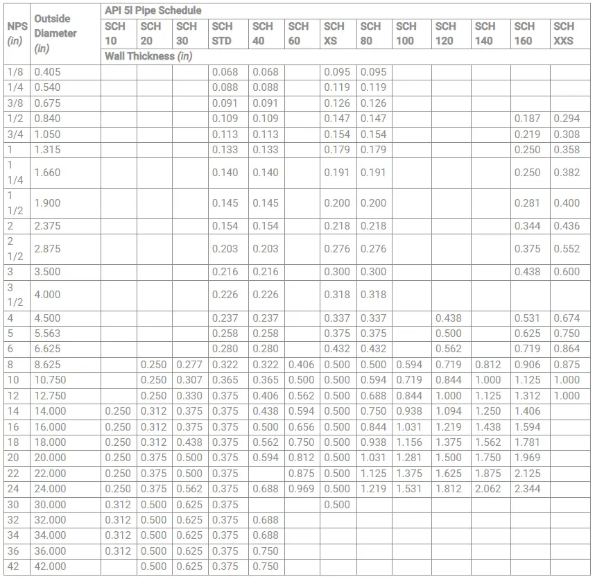
Manufacturers of API 5L pipes provide their schedule chart mentioning the available pipe thicknesses with respect to pipe size. The weights and prices per unit length are also usually provided in the API 5L pipe schedule chart. Some grades of pipe schedules like API 5L grade pipes have standardized pipe schedules similar to as provided in ASME B36.10. But for high-strength line pipes, for example, X60, X52, X42, etc have standardized as well as non-standardized pipe schedules.
A typical API 5L standardized pipe schedule chart is provided in Fig. 1 below.
Fig. 1: API 5L Standardized Pipe Schedule Chart
What is a Chemical Injection Quill? Types, Configurations, Applications
The injection quill is a precision-engineered mechanical device. As this device is widely used in the chemical injection process it is popularly known as the chemical injection quill. Various chemical industries use injection quills to provide an effective and safe means of injecting liquid chemicals into a vessel or pipeline system. They are usually a part of metering systems.
Applications of Chemical Injection Quills
Injection quills dose the chemical into the interior section of the flow and thereby keeping the chemical away from the sidewall and fittings. Chemical injection quills serve as an interface between the chemical feed line and the processing pipeline. The quill delivers the chemical efficiently into the interior of a process pipeline flow. Various chemical industries make use of chemical injection quills in applications like additive injection, bio-treatment, chemical injection, removal and separation processes, etc.
Chemical injection quills are used in a wide range of industries and processes, including:
Water Treatment: In water treatment applications, chemical injection quills are used to introduce chemicals such as chlorine, chlorine dioxide, coagulants, and pH adjusters into the water to disinfect it, remove impurities, and maintain the desired water quality.
Oil and Gas Industry: Chemical injection quills are employed in the oil and gas sector to introduce chemicals that aid in pipeline maintenance, inhibit corrosion, prevent scale formation, and enhance oil recovery during production.
Chemical Manufacturing: In chemical production processes, quills are utilized to introduce catalysts, reactants, and additives into reaction vessels for precise control of chemical reactions.
Pharmaceuticals: Chemical injection quills play a role in pharmaceutical manufacturing by accurately introducing active pharmaceutical ingredients (APIs) and other substances during drug synthesis.
Wastewater Treatment: In wastewater treatment plants, chemical injection quills are used to introduce chemicals for flocculation and coagulation, aiding in the removal of suspended particles and pollutants.
Types of Chemical Injection Quills
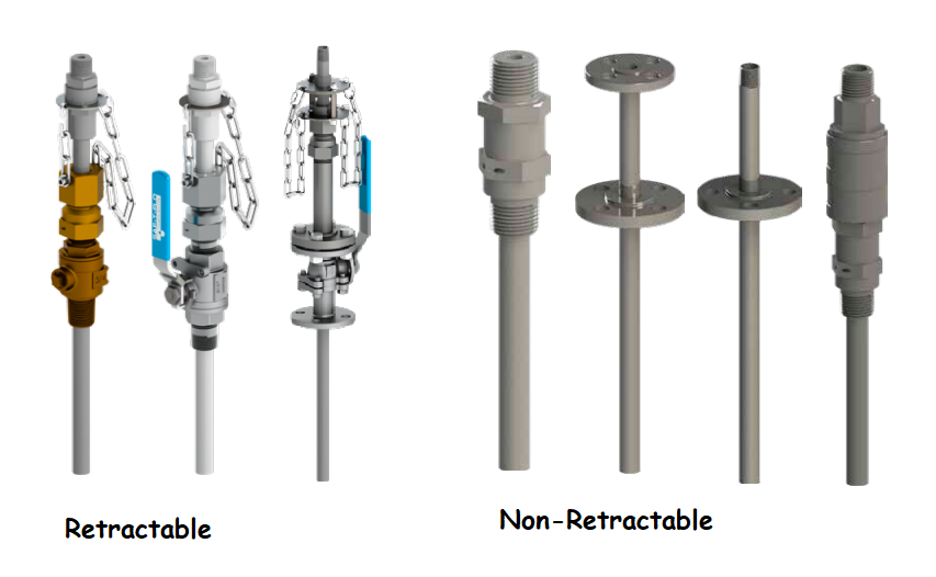
To meet the demand for handling various chemical substances, there are a wide variety of injection quills that are found in industrial applications. All these chemical injection quills are categorized into one of the following two types:
Retractable Quills allow the operator to retract the injection quill without fully depressurizing the vessel or pipeline. These types of injection quills are complex in design and highly beneficial for clog-prone systems requiring frequent maintenance but where frequent shutdown is not feasible.
All retractable injection quills have the following components:
Solution Tube that carries the treatment chemical.
Restraint system to keep the solution tube in place.
Isolation valve assembly consists of a valve and compression gland.
Non-Retractable Quills where the vessel or pipeline must be depressurized to remove the chemical injection quill. Non-retractable types of injection quills are widely used for chemical systems that do not form frequent deposits to clog the quill.
Fig. 1: Retractable vs Non-retractable Injection Quills
Depending on the number of Ports, injection quills are classified as follows:
Dual Port Injection Quill: These types provide a uniform and rapid dispersal of two chemicals injected into one port.
3-port Injection Quill: Deaerators, boilers feed water tanks, etc use this type of injection quill for more uniform and rapid dispersal of chemicals into the center of the process pipe.
4-port Injection Quills: These are specially designed injection quills to disperse four chemicals into one port.
Chemical Injection Quill Configurations
Industrial injection quills are manufactured in various configurations, connections, and fittings. The configuration varies from a simple fabricated tube/probe to an integrated assembly with isolation valves and non-return valves. A compact integrated assembly consisting of the chemical injection quill, probe, double block & bleed assembly, and an integral non-return check valve is always beneficial.
Injection quills can be used as sampling quills by redesigning the probe and removing the integral check valve to safely take out fluid samples from the process line.
Chemical injection quills are mounted into the pipeline through a fitting. The probe is inserted and extended to the center of the process line. The other end of the injection quill connects to the chemical feed line by a pipe or tubing connection.
Designing An Injection Quill
The design of an injection quill is governed by various parameters like:
Design calculation
The wake frequency is calculated following the guidelines provided in the ASME PTC 19.3 TW standard for Thermowell as the injection quill is similar to it. The design of chemical injection quills needs both thermal and stress considerations. So process parameters like fluid, temperature, pressure, velocity, flow rate, density, viscosity, etc must be known for designing the injection quill.
Material of Construction
The material grade of the injection quill is selected such that the material is suitable for the service and the chemical to be injected. As the quill forms an integrated assembly together with the DBB and the check valve, several parameters similar to an isolation valve design must be evaluated.
Dimensions
The length of the injection quill is one of the most important parameters for wake frequency calculation. The length can be customized. Bore Size, Insertion Length, Tip Diameter, Root Diameter, Overall length, etc are the important dimensions to be considered during design.
Nozzles
In general, cylindrical tubes or nozzles are used for injection quills. However, specially designed nozzles depending on the application can be designed.
Mounting options
The design of injection quills can vary based on mounting options. Various different mounting options like flanged, welded, or threaded are possible. However, the quill/probe outside diameter (O.D.) must fit all the way down to the process stream.
Working Principle of Chemical Injection Quills
When the chemical injection pump operates, it pushes the chemical through the quill, which has a small orifice or series of holes at its tip. As the chemical is released into the fluid stream, it undergoes turbulent mixing with the surrounding fluid, promoting rapid dispersion and integration. The quill’s design helps prevent direct contact between the chemical and the pipe walls, which could lead to unwanted reactions or buildup.
Components of a Chemical Injection Quill Assembly
A chemical injection quill assembly consists of several essential components that work together to introduce chemicals or substances into a fluid stream. The specific design and configuration of the assembly may vary depending on the application and the requirements of the system. Below are the main parts commonly found in a chemical injection quill assembly:
Injection Quill Body: The injection quill body is the main component of the assembly, usually a hollow tube or pipe made from materials compatible with the chemical being injected and the fluid in the system. It connects to the chemical injection system, such as a pump or storage tank, at one end.
Injection Orifice or Holes: At the tip of the injection quill, there is an injection orifice or a series of small holes. These openings are responsible for releasing the chemical into the fluid stream. The size and number of orifices or holes are critical to achieving the desired injection rate and dispersion.
Flange or Connection End: The end of the injection quill assembly that enters the fluid stream is typically flanged or threaded for easy installation and connection to the process piping. The type of connection used depends on the specific requirements of the system.
Flange Gasket: A flange gasket is placed between the flange on the quill and the process pipe to create a secure and leak-free connection. The gasket material is chosen to be compatible with the fluid and the chemical being injected.
Supports or Holders: Depending on the installation and process conditions, the injection quill may be supported by holders or brackets to keep it stable and properly positioned in the fluid stream.
Injection Tube Extension: In some applications, a tube extension or extension pipe is attached to the injection quill to ensure that the chemical is introduced at the optimal location within the fluid stream. This extension can vary in length depending on the specific requirements of the process.
Ball Check Valve (Optional): Some chemical injection quill assemblies may include a ball check valve to prevent the backflow of fluid into the quill. This check valve ensures that the chemical flows only in the desired direction.
Stabilizing Fin (Optional): In certain applications, the injection quill may have stabilizing fins or vanes attached to the body. These fins help stabilize the quill in high-velocity fluid streams, reducing vibration and potential damage.
Pressure and Temperature Sensors (Optional): In advanced quill assemblies, pressure and temperature sensors may be integrated to monitor the fluid conditions and provide feedback for process control.
Chemical Injection System: Though not a part of the quill assembly itself, the chemical injection system, such as a chemical injection pump or storage tank, is an essential component that feeds the chemical into the injection quill.
It’s essential to ensure that the materials used in the construction of the chemical injection quill assembly are compatible with the chemicals being injected and the fluids in the process to avoid any chemical reactions or material degradation that could affect the system’s performance and integrity. Regular inspection, maintenance, and monitoring of the quill assembly are also crucial to ensure safe and efficient operation.
Selection of Injection Quills
The selection of required injection quills depends on the following factors:
Retractable or Non-Retractable
Key dimensions like solution tube size, process connection size, insertion length, pressure class rating, etc.
Materials of Construction required.
Advantages of Chemical Injection Quills
The use of chemical injection quills offers several advantages:
Uniform Dispersion: The quill’s design ensures that the injected chemical is uniformly dispersed within the fluid stream, preventing localized concentrations and ensuring effective mixing.
Minimal Contact with Pipe Walls: The quill helps minimize direct contact between the chemical and the pipe walls, reducing the risk of chemical reactions or scale buildup that could hinder flow and affect system performance.
Precise and Controlled Dosing: Chemical injection quills allow for accurate and controlled dosing of chemicals, ensuring the correct amount is introduced into the system.
Easy Installation and Maintenance: Quills are relatively easy to install and maintain, making them a practical choice for various applications.
In conclusion, chemical injection quills are essential components in many industrial processes where precise and controlled chemical dosing is required. Their ability to uniformly disperse injected chemicals ensures effective performance and reliable results in diverse applications, ranging from water treatment to oil and gas production and beyond.
Types, Applications, and Selection of Choke Valves for Oil and Gas Operations
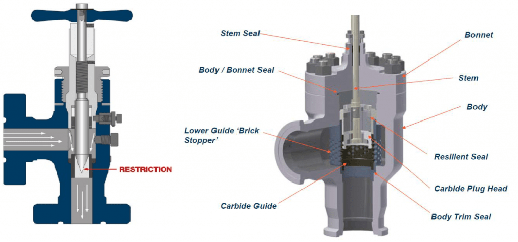
Choke valves or choker valves are a type of severe service control valve that is widely used in oil and gas production wells. They control the flow of well fluid. Additionally, Choke valves act to kill the reservoir pressure and regulate the downstream flowline pressures. A choke valve consists of a plug or stems that move up and down inside a slotted cylinder to control the flow.
Choke valves are very robust in design to handle severe extreme conditions of high corrosion, erosion, high fluid velocity, wide ranges of flow rates, marine environmental conditions, etc. It has the ability to handle extreme pressure drops in the range of 500 bars. Choke valves are usually designed based on API codes (API 6A/6D). Refer to Fig. 1 below that provides a typical cross-section of a choke valve.
Fig. 1: Typical Choke valve Cross-Section
Applications of Choke Valves
Choke valves are found in a variety of applications. Some of the common uses of choke valves are:
Depending on the function of the choke valves they are classified into two groups. They are:
Regulating choke valves and
Non-regulating choke valves.
Regulating Choke Valves
This type of choke valve acts as a flow control valve. These valves are capable of maintaining steady production levels in production headers and flowlines. It is an automatic valve where an electric signal from the panel controls the opening of the valve.
Non-regulating Choke Valves
Non-regulating choke valves act as an On-Off valves. The opening of these types of choke valves is designed in such a way that it can remove pressure when in fully open condition. As the name suggests, they do not regulate or control the flow.
Depending on the orifice size, there are two types of choke valves.
Positive Choke valve having a fixed orifice size, and
Adjustable choke valves with a variable orifice size with an external adjustment device to vary the orifice size.
Depending on the design and construction of the choke valves they are grouped into the following types:
Needle and Seat Choke valve: simple design of positive choke with a cone-shaped plug, rising stem, and handwheel.
Plug and Cage choke valve: complex design with ported cages arranged to provide a great combination of flow and control capability.
The Port cage of the choked valve can be of various types like:
4-port cage: Used for well-site separators and line heaters.
Multi-ported cage: for high-pressure drop critical applications.
Plug and cage design: for high-capacity applications.
Choke Design
To make better use of the gas for natural gas lift and to control the bottom hole pressure for recovery reasons, chokes hold back pressure on a flowing well. With decreasing hydrostatic head, the gas expands rapidly in vertical pipe flow, and the liquid moves in slugs through the tubing. This causes the potential gas lift energy to be rapidly lost. In turn, the liquids fall back and begin to accumulate over the perforations. These accumulating liquids hold back pressure on the formation. When enough liquids accumulate, the well may “die” and quit flowing.
The choke holds this backpressure by restricting the flow opening at the wellhead. The uncontrolled expansion and rise of the gas are restricted by the back pressure. It thus helps keep the gas dispersed in the liquids on the way up the tubing.
Chokes may have a variable or a set opening. The set openings, known as “beans,” are short flow tubes. They graduated in 1/64ths of an inch. Common flow sizes are about 8 through more than 20 (in 64ths) for small to moderate-rate gas wells.
Depending on the reservoir pressure, tubing size, amount of gas, and the amount and density of liquids, the size of the choke varies. To allow quick resetting, variable chokes may use an increasing width slot design. They are useful on well-cleanups following stimulation where choke size can vary over the course of a single day. They can also be used for periodic liquid unloading that necessitates frequent choke size changes.
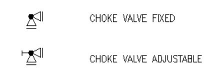
Choke valve Symbols
Chokes valves are usually denoted by the following symbol in P&IDs.
Fig. 2: Choke Valve Symbols
Functions of a Choke Valve
A choke valve mainly performs the following three main functions:
Changing the flow rate by controlling the choke cross-section.
Loading resistance, and
Pressure buffering by hindering the fluid flow to a certain extent.
Working Principle of a Choke Valve
The main purpose of a choke valve is to restrict the flow through the valve to have the desired flow rate. This is achieved by reducing the flow area through the valve body. The adjustable choke valves control the flow rate by adjusting the stem and seat combination. The handwheel can be turned to set the orifice size and flow coefficient which in turn produces the required flow rate. In the case of positive choke valves, a fixed flow rate is achieved through the use of a choke bean.
Selection of Choke Valves
Choke valves are carefully selected based on applications and various factors like size, material, trim design, etc. The parameters that influence the selection of choke valves are:
Choke valves are widely used in oil and gas production facilities because of their reliability and safe handling of high operating pressures. The main advantages of choke valves are:
High reliability
High rangeability
Controlled erosion
Low noise
The ability of pressure balancing
Accurate flow rate adjustment
Long service life
Further Studies
More details about the choke valves can be accessed by clicking here.