A stud bolt is an externally threaded mechanical fastener. An assembly of stud bolt connections is usually formed by two nuts and the stud. Sometimes, washers and additional nuts may be used. In high-pressure piping and pipeline flange connections, stud bolts are widely used. In this article, we will learn about the types, standards, materials, selection, and sizes of stud bolts.
What is a Stud Bolt?
A stud bolt is a mechanical fastener having external threads without a head. The external thread is either for the full length of the stud or partially threaded from each end. It uses at least two nuts, one on each side for assembly connection. Stud bolts are available in various sizes, types, and threading patterns.
Types of Stud Bolts
Depending on the threading pattern and design, various types of stud bolts are available as listed below:
Fully threaded stud bolt or continuous threaded stud bolt having uniform thread throughout its length.
Tap end stud bolts having unequal threads from each end and non-threaded center.
Double-end stud bolts having both ends threaded of equal lengths and a non-threaded center.
Flange Stud bolts: Fully threaded stud bolts with chamfered ends specifically used for flanged connections.
Double-end stud bolt with reduced shank: the non-threaded center part is of a reduced diameter than the actual diameter.
Depending on the Stud bolt material strength they are divided into three groups;
High-Strength stud bolt
Intermediate-strength stud bolt, and
Low-strength stud bolt.
Types of Stud Bolt Threads
Stud bolts use a variety of screw thread profiles depending on the application. Some of the most common thread profiles are:
ISO metric thread
ACME thread
UNC thread
UNF thread
UN thread
WHITWORTH thread
Stud Bolt Standards
The design and manufacturing of stud bolts are governed by a range of ASME standards as listed below:
ASME B16.5 & ASME B16.47 cover the diameter and length.
ASME B1.1 covers coarse and fine thread series.
ASME B18.2.1 is used for Square and Hex Bolts and Screws
ASME B18.2.2 provides details for Square and Hex Nuts
ASME B18.21.1 provides Lock Washer details
ASME B18.22.1 is used for Plain Washers
Various other international standards like DIN, ISO, BS, SAE, IS, etc also provide details of stud bolts.
Stud Bolt Materials
For high-temperature and pressure services, ASTM A193 is the most widely used flange material. Grade B7 and B7M are the most frequently used A193 material grades. For low-temperature services, ASTM A320 Gr L7, L7A, and L7B are used. Other stud bolt materials include the following:
The nut and washer material must be compatible with the selected stud-bolt material to avoid galvanic corrosion. Sometimes stud bolts are coated to increase corrosion resistance. The common coating materials are:
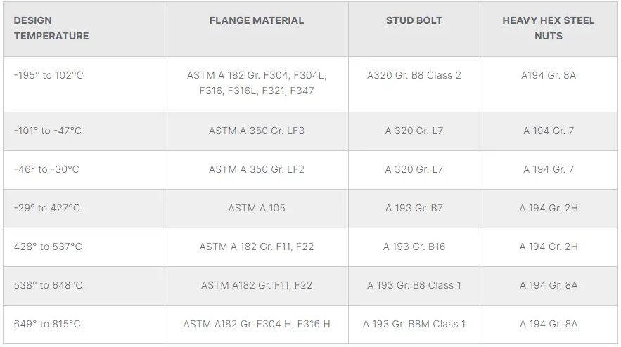
The material of the stud bolt mainly depends on the process design temperature and flange materials. however, there are many other parameters that must be considered. The following image from blog.projectmaterials.com provides rough guidance on the stud bolt material selection based on design temperature and flange material:
Fig. 1: Stud Bolt Material Selection
Stud Bolt Ends and Lengths
The ends of stud bolts are usually rounded, sheared, saw cut, flat, or chamfered. The length of a stud bolt is measured parallel to the axis from one end to the other. They are available in 1/4″ length increments.
Stud Bolt Size/Dimension
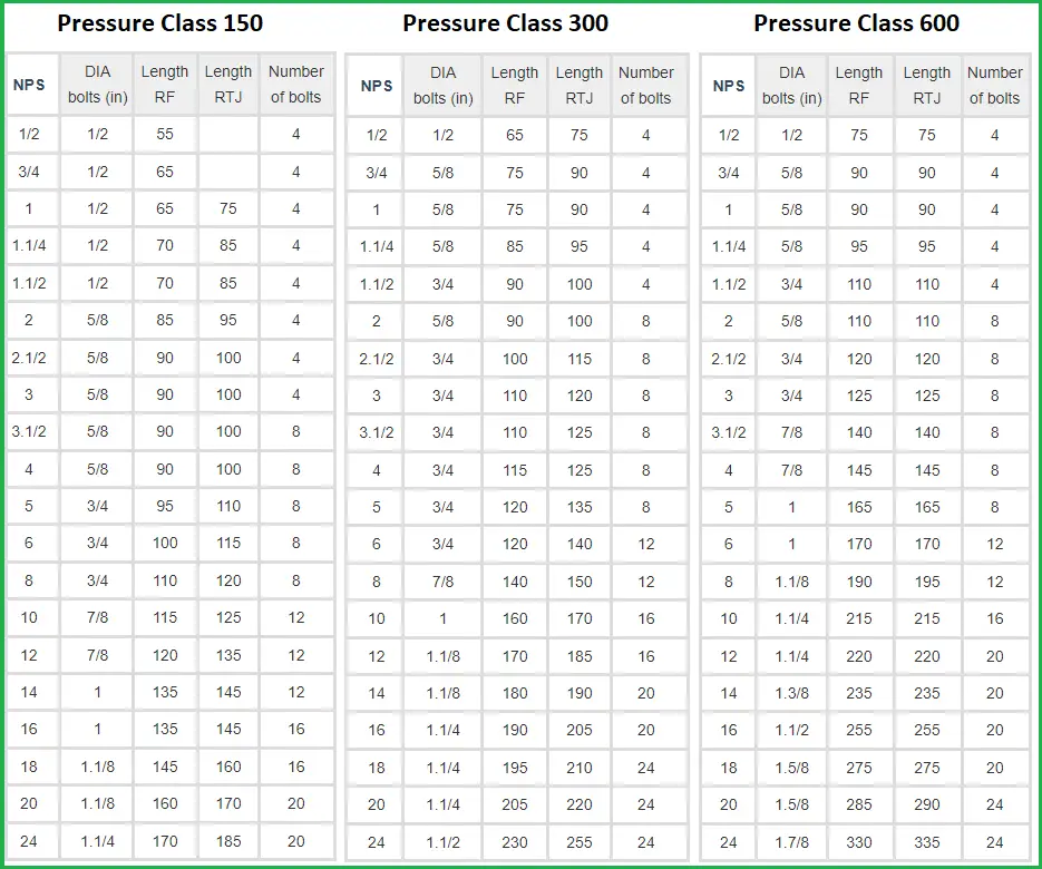
The size and dimension of the stud bolt are decided by the governing standard. ASME B16.5 and ASME B16.47 provide stud bolt charts that provide the bolt diameter and the number of bolts required depending on the pressure class, flange type, and pipe size.
In general, with an increase in pressure class and NPS, the bolt area increases. There are two parameters that decide the bolt area; bolt diameter and the number of bolts. So, any of the two or both parameters can increase to get an increase in bolt area. Refer to Fig. 2 below for a typical Stud-bolt chart for pressure class 150, 300, and 600 based on ASME B16.5 standard.
Fig. 2: Stud Bolt Chart and Dimensions for 150, 300, and 600 Pressure Class
What is Nitrogen Blanketing? Purpose, Procedure, and Applications of Tank Blanketing
Nitrogen blanketing is the process of supplying the N2 (or other inert gas) gas to the vapor space of a container to control its composition. It provides improved process safety and better product quality, along with a longer equipment life cycle. Nitrogen blanketing practices can be applied to a wide variety of container sizes. The process is widely used for storage tanks, and because of that, nitrogen blanketing is often termed tank blanketing, tank padding, or nitrogen padding. In this article, we will explore more about nitrogen blanketing: its procedure, purpose, application, and controls.
What is Nitrogen Blanketing?
Nitrogen blanketing is the process of supplying the storage tank with an inert gas (the most economical), such as nitrogen, to counteract the effect of oxygen (and other reactive gases) on the storage material, which is usually liquid. When purging the vessel with inert or inert gas, the vessel material does not come into contact with oxygen. This extends product life and mitigates potentially explosive conditions by reducing the risk of chemical reactions, corrosion, and fire hazards.
Applications of Nitrogen Blanketing
Nitrogen blanketing is used in all industries wherever flammable or explosive products are used or generated. Some of the industries that widely use nitrogen padding methods are:
Chemical Plants and Petrochemical Industries: In these sectors, nitrogen blanketing is crucial for preventing unwanted chemical reactions and ensuring the stability of sensitive products. It helps maintain the purity of chemicals and pharmaceuticals by preventing contamination.
Oil and Gas Industry: Nitrogen blanketing is employed to safeguard storage tanks and pipelines containing volatile substances. It prevents the formation of explosive mixtures and minimizes the risk of corrosion.
Food Processing: To extend shelf life and preserve the quality of food and beverages, nitrogen blanketing is used in packaging and storage. It helps prevent oxidation, which can lead to spoilage and degradation.
Electronics Manufacturing: Nitrogen blanketing is used in the manufacturing of electronic components to prevent oxidation and contamination of sensitive materials.
Pharmaceutical industries
Petroleum Refining plants
Aerospace industries
Ships and Transformers
Chemical and Petrochemical Transportation Industry,
Chemical tankers
Personal Care, Cosmetics, and Semiconductor.
Gas blanketing is used to protect a diverse range of products, including but not limited to adhesives, catalysts, chemicals, fragrances, fuels, industrial coatings, inks, deionized water, fats and oils, flavors, foods, juices, pharmaceuticals, photographic chemicals, solvents, volatile combustibles, sealants, soaps, and water for injection.
Purpose of Nitrogen Blanketing
The blanket helps to maintain constant inert conditions for the product in the container. The goal is to prevent explosion, discoloration, polymerization, and other unwanted quality changes. Here, the flow and pressure of the inert gas stream and/or the oxygen level in the exhaust gas will control the operation. The main benefits that a nitrogen blanketing system provides are:
Increased safety by reducing the explosion possibility by reducing the amount of oxygen in the vapor space of a chemical storage tank.
The reduced potential of fire and explosion.
Increased equipment life by reducing the corrosion possibility due to oxygen and moisture reactions.
Reduced chances of product degradation by creating the blanket.
Reduced possibility of product property alteration.
Decreased product evaporation
Enhanced overall efficiency of industrial processes by eliminating contamination.
Nitrogen blanketing can be applied to a variety of container sizes from a multi-million-gallon tank to a large or smaller container. Although blanketing is a factory practice, there is scope for improvement. Bad choices may add costs, increase nitrogen wastage, or increase plant emissions.
Nitrogen Tank Blanketing Procedure
Before diving into the nitrogen blanketing procedure, let’s recapitulate some of the basics. We all know that a fire happens when all three elements; an ignition source, fuel, and oxygen are present. Removing any of these three elements will remove the possibility of fire. The space above the tank contains a mixture of air and steam from flammable materials that are being stored, eg solvents.
Mixtures of solvent vapors and air will only ignite and burn if the vapor mixture is within the flammability of the solvent and an ignition source is present. This can lead to tragic consequences such as serious injury to people.
Static charges can develop within the system or within the solvent itself, creating a source of ignition although storage tank facilities may be electrically grounded to reduce the probability of ignition.
A storage tank can be made inert in any of the following three ways:
Limiting the Oxygen Concentration (LOC) of the vapor space
Reducing the fuel concentration below the Lower Explosion Limit (LEL), or
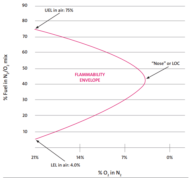
Increasing the fuel concentration above the Upper Explosion Limit (UEL).
The manufacturer’s Material Safety Data Sheet (MSDS) provides the values of LEL and UEL for a chemical. LOC values are often found in chemical industry handbooks and guides such as the National Fire Protection Association (NFPA) Guide. Flammability limits of mixtures of gases, combustibles, and inert substances for high temperature and pressure can be determined by computational methods.
Refer to Fig. 1, which provides a sample example of a flammability envelope for Hydrogen in Air. The combustion will not take place beyond the LOC.
Fig. 1: Flammability Diagram of Hydrogen in Air
When considering a new or improved blanketing design, the first factor to take into account is the type of tank. This will determine if blanketing is required or not. The following rules apply to the storage tanks for the nitrogen blanketing philosophy.
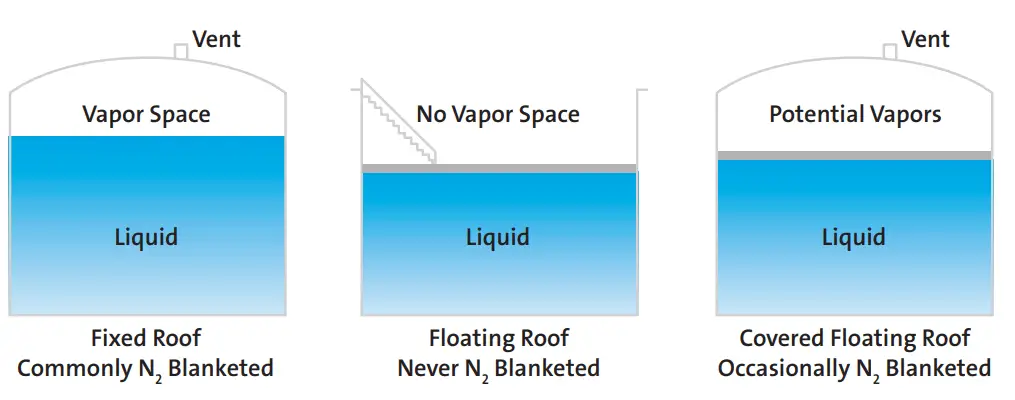
When a fixed roof tank stores any flammable material, nitrogen blanketing must be applied.
Floating roof tanks do not need tank padding.
Internal floating roof tanks or covered floating roof tanks occasionally need nitrogen blanketing as there is the possibility of vapor build-up.
Fig. 2 explains the above concept of storage tanks requiring nitrogen blanketing.
Fig. 2: Nitrogen blanketing requirement for Storage tanks
In addition to the storage tanks and similar vessels, a number of sealed tanks like Non-pressurized spaces may also require blanketings, such as a pneumatic conveyor, powder and dust hoppers, or controlled atmospheric tanks.
The nitrogen blanketing procedure maintains a concentration of nitrogen within the padded tank/vessel. It also prevents the reintroduction of oxygen and other gaseous contaminants within that region. The nitrogen blanketing procedure usually employs the following methods:
Automatic pressurized vessel purging
Continuous pressurized nitrogen blanketing using manual controls
Oxygen concentration measurement and variation
Dual oxygen concentration and pressure monitoring
Maintaining a steady pressure of gaseous nitrogen and eliminating oxygen.
Nitrogen Control by Continuous Purge
The continuous purge system uses a continuous flow of nitrogen, which is simple to do but can lead to high nitrogen consumption. Nitrogen can also remove vapor in the headspace and put more uploads factory emissions management system. In addition, air may enter empty space if the tank is empty too quickly and the liquid level drops too quickly. Despite these problems, this type of system continues to be used because It’s very simple and quick to make. Replace this method with pressure or concentration control can lead to savings.
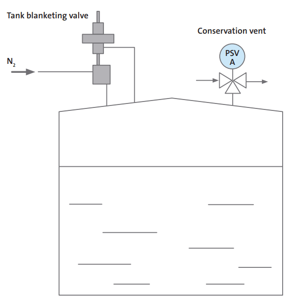
Nitrogen Control by Pressure Control
Fig. 3: Pressure Controlled Nitrogen Blanketing
Pressure control systems are used for closed tanks, that can hold pressure. A valve detects pressure in the headspace of the tank and supplies nitrogen accordingly. Headspace pressure control can be set quite low; less than an inch in the water column is enough. When the tank is discharged, the liquid level is dropped, pressure is reduced, and nitrogen is added. When the tank fills, the pressure increases, and nitrogen escapes through the vent valve.
Nitrogen Blanketing Calculation
Simple Calculations for nitrogen requirement are shown where basically, the nitrogen requirements of blanketed tanks have two parts:
Nitrogen as required by the flow, or material flow through the tank(NW); and
Nitrogen is required by heat breathing or the increase and decrease of the liquid level due to external temperature (NTB). Of these two sections, usually, the NTB is significantly larger.
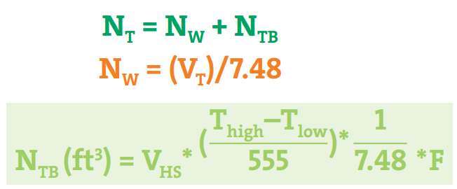
The equations mentioned in Fig. 4 are used to calculate the N2 requirement for the Nitrogen blanketing process.
Fig. 4: Calculation of Nitrogen Requirement for Nitrogen Blanketing
Here,
NT= Total volume of nitrogen required per month (ft3)
NW = Required Nitrogen by the material flow through the tank (working throughput)
NTB = Required Nitrogen by the rise and fall of the liquid level owing to the external temperature conditions (thermal breathing)
VT= total gallons discharged from the tank per month
VHS = Average empty headspace (gal)
Thigh = Maximum temperature in the tank (°F)
Tlow = Minimum temperature in the tank (°F)
F = Estimated number of temperature swings per month
555 = A constant (˚R) pertaining to the vapor space expansion factor
7.48 = Gallons to the cubic feet conversion factor
Components of a Nitrogen Blanketing System
A nitrogen blanketing system is designed to create and maintain an inert atmosphere within a container, tank, or pipeline to prevent contamination, oxidation, and other issues. The primary components of a nitrogen blanketing system include:
1. Nitrogen Supply
Nitrogen Generator: Produces nitrogen on-site from ambient air, usually through processes like pressure swing adsorption (PSA) or membrane separation. It ensures a continuous supply of nitrogen.
Nitrogen Cylinder or Tank: Stores nitrogen gas if it is supplied in bulk or as a compressed gas.
2. Flow Control Components
Flow Meter: Measures the rate at which nitrogen is being introduced into the system. This ensures that the right amount of nitrogen is supplied to maintain the desired blanket.
Regulator: Controls the pressure of the nitrogen gas before it enters the container or system. It ensures that the pressure is maintained at a level slightly above atmospheric pressure to prevent ingress of air.
3. Pressure Control Components
Pressure Relief Valve: Protects the system from overpressure conditions by releasing excess nitrogen if the pressure exceeds a preset limit.
Pressure Transmitter/Sensor: Continuously monitors the pressure within the container or system. It provides real-time data for maintaining the correct nitrogen blanket.
4. Blanketing and Purging Components
Blanketing Valve: Controls the flow of nitrogen into the container to maintain the desired pressure and blanket level.
Purging System: Used for initial nitrogen purging to remove any existing air or contaminants before the blanketing process begins.
5. Monitoring and Control Systems
Control Panel: A centralized unit that integrates various sensors, meters, and control valves. It allows operators to set and adjust parameters such as pressure and flow rate.
Alarm System: Provides alerts for abnormal conditions such as pressure deviations or equipment malfunctions, ensuring timely intervention to maintain system integrity.
6. Safety Devices
Check Valve: Prevents backflow of nitrogen or other substances into the nitrogen supply lines, ensuring system safety and reliability.
Ventilation System: Ensures that any excess nitrogen or displaced gases are safely vented to avoid hazardous conditions or buildup.
7. Additional Components
Filters: Remove particulates and contaminants from the nitrogen supply to prevent damage to sensitive equipment and ensure the purity of the inert atmosphere.
Temperature Control: Some systems include temperature regulation components if the process is sensitive to temperature variations.
Importance of Nitrogen Blanketing Valve
A nitrogen blanketing valve is a specialized valve used in nitrogen blanketing systems to control the flow of nitrogen gas into a container, maintaining an inert atmosphere. Its primary function is to regulate the pressure inside the container, ensuring it remains slightly above atmospheric pressure to prevent the ingress of air, moisture, and contaminants. This helps protect sensitive products from oxidation, contamination, and potential hazards, while also safeguarding equipment and ensuring safe and efficient operations.
In conclusion, nitrogen blanketing is a vital technique in modern industry, providing safety, quality, and efficiency benefits across a range of applications. Whether in chemical processing, food production, electronics manufacturing, or oil and gas, nitrogen blanketing plays a crucial role in ensuring optimal conditions and safeguarding valuable assets.
Reference and Further Studies
To learn more about the subject refer to the following article: https://www.chemicalprocessing.com/assets/wp_downloads/pdf/nitrogen-blanketing-keeps-employees-and-equipment-safe.pdf
The scope of a cooling water system is to provide the necessary cooling duty to heat exchange equipment and rotating equipment for removing the unrecoverable heat excess, no more easily and economically exploitable.
Cooling duty is always a lost duty; therefore cooling water should be used only when the heat cannot be recovered by other means. The cooling water system is considered to be a critical utility system; local or total loss of cooling water is a primary cause of process plant upset with failure of machinery equipment, column pressurization; leads to, PSVs opening; causes plant or complex shutdown, depending on the complexity of the CW network. Therefore the reliability of operation of the system components and the equipment sparing philosophy have primary importance.
Selection of Cooling Water System
A cooling water system should be used when the process heat is available at a low temperature (below 60°C), no more easily exploited, and the process outlet temperature must be lower than the ambient air temperature. This is the reason why it’s common to use an air cooler with a water cooler downstream; the temperature limit between the air cooler outlet and the water cooler inlet is the one indicated above.
The aforementioned temperature ranges shall be taken as a reference for selecting the appropriate cooling system. They depend on on-site conditions; the edge temperature value could be shown in Client documentation (BEDD). Site conditions limit the design options and the possible ways to operate the cooling system. They are defined by the local climate, the availability of water for cooling and discharge, the available space for construction, and the surrounding area’s sensitivity to emissions.
The local climate affects the temperature of the cooling water and air.
In general, cooling systems are designed considering the cooling requirements under the least favorable climatic conditions that can occur locally, i.e. with design values of wet and dry bulb temperatures. These data should be stated in BEDD.
The higher the bulb temperatures the more difficult is to cool down to low-end temperatures of the process.
Configuration of Cooling Water System
There are different types of cooling water systems: lake or basin cooling, once-through, open recirculation (evaporative), and closed recirculation (not evaporative).
Lake or Basin Cooling
In this kind of cooling system, the water used to cool down the excess heat of the process is discharged directly into a lake or basin where is cooled gradually by means of natural evaporation, radiation, and convection at a suitable temperature to re-use.
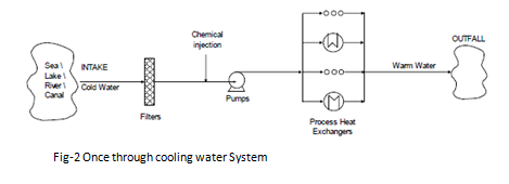
Once through system
Cooling systems that use cooling water on a one-time basis before discharging it directly to the outfall are termed once-through cooling systems. Since even small cooling systems operating on a once-through basis use relatively large amounts of cooling water, these systems are generally employed only where water at a suitably low temperature is readily available in large volumes and at low costs.
The usual source of once-through cooling water is from the sea; rivers or lakes (see Figure 2).
Fig. 2: Once-Through Cooling Water System
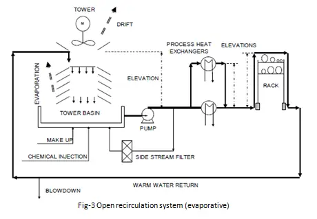
Open recirculation system (evaporative)
An open recirculation system incorporates a cooling tower to dissipate the heat removed from the process. It takes water from the cooling tower basin, passes water through equipment requiring cooling, and then returns the warm water to the evaporation unit, where the evaporated water cools down the water that recirculates.
The open recirculation system repeats the process of reuse, taking insufficient freshwater makeup to balance the water evaporated and drifted and the blow-down from the system to control the chemical characteristics of the recirculation water. This greatly reduces water demand and discharge. However, such a system also intensifies the potential for scaling, fouling, and corrosion. The number of concentration cycles should normally be in the range of 3 to 5 unless very strict requirements forced to use a lower number;
If fresh sweet water is not available for make-up, an evaporative system with seawater can be used, if the site is close to the sea. The open recirculation system uses only 10% of make-up flow compared with the total flow of a once-through system with seawater. For a seawater evaporative system, the number of concentration cycles must be kept at only 1.2, max of 1.3. With seawater, materials are of course more valuable than an evaporative system with sweet water. A disadvantage of the seawater evaporative system is the formation of saline moistness close to the sea cooling towers.
Fig. 3: Open recirculation System
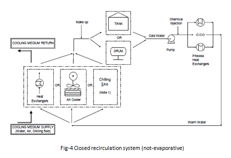
Closed recirculation system (not-evaporative)
In a closed recirculation system, water is recirculated in a close circuit with negligible evaporation or exposure to the atmosphere or other influences that would affect the chemistry of the water in the system. Heat is transferred to the closed cooling water system by typical heat exchange equipment and is removed from the closed recirculation system by a second exchange of heat from the closed system to a secondary cooling system. The secondary system could use either evaporative or once-through cooling or air cooling.
These systems usually require strong chemical treatment on the make-up water but, since water losses are negligible and make-up water flow is low, these treatments do not affect too much the operating costs. High-quality make-up water is generally used for the best system operation.
Make-up water flow is low (0.1 – 0.5% daily of the circuit volume) and is used only to replace the small losses from the system.
Fig. 4: Closed-Recirculation System
Selection of the Cooling Item for a Recirculation System
Return warm water coming back from users can be cooled down to reach the cold temperature by use of:
Cooling tower:
Water is cooled down by heat exchange with ambient air and evaporation of a part of the water itself. A quite large flow rate of water is required as circuit make-up, to compensate for evaporation losses, water drift with the air, and water blow-down used to keep low the dissolved solid content.
Cooling towers provide a good, stable, flexible, and easy-to-maintain way of cooling down the water. Tower materials (cement, wood) are easy to find and low cost. An important part of the job for the cooling tower is the design of the basin, that collects water to be pumped out, which should follow the American National Standard for Pump Intake Design by Hydraulic Institute. Cooling towers and relevant basins are not a complete package; they must be specified in two different datasheets because tower civil works like basins are normally not included in the Vendor’s scope of work. Moreover, very stringent local laws or environmental regulations could not permit to discharge of the tower blow-down to the ambient (roughly estimated as 3% of the total circulating flow, depending on the quality of water).
Heat exchanger:
It is a classic heat exchanger, usually a plate heat type. Delta temperature between cold and hot sides should be kept with some degrees of approach (3°C minimum) not to increase too much the exchange surface and not to increase the temperature of the cooling water. Plate heat exchanger permits a lower temperature approach than shell and tube, reducing the exchange surface and cost and limiting the space occupation on the plot.
Materials of the exchangers can be often valuable, especially when seawater is used (Titanium). This is an important reason to consider an indirect cooling water system and not use seawater for the entire once-through cooling water system. Using a seawater / CW exchanger, only this item is designed with valuable material, while in a direct once-through system with seawater, all the process equipment must be designed with suitable materials. Pressure on the SW side is lower than on the CW side to minimize leakages from SW to CW.
Air cooler:
The air cooler does not have material problems and has low operating temperature and pressure conditions. Therefore, its design is quite simple. With the increase of duty to be disposed of, the space occupied in the plot plan can become very large, depending also on the design dry-bulb temperature and from the CW outlet
temperature. Space can be kept to a minimum by installing air coolers above other process equipment or a pipe rack. Air cooling systems have limits regarding their location as they cannot be placed too close to equipment that causes heating of the air because of the resulting possible air recirculation.
Air coolers cannot be placed too close to buildings due to noise and warm air.
Selection of Cooling Water temperature levels
As stated before, the selection of CW temperature levels is important for the optimization of plant costs.
Once-through system:
Cold cooling water temperature will be defined considering the maximum temperature of the water source during all seasons. The CW delta T through the process exchangers shall be defined considering the respect to the World Bank limits is a maximum increase of the temperature at the outlet of 3°C at 100 meters far from the outfall point. Consider also environmental limits due to local law.
When using seawater the outlet temperature from each process cooler shall never exceed 46°C to avoid deposits produced by crystallization or precipitation of sparing soluble salts.
Recirculation system:
The selection of temperature levels depends mainly on the mean used to cool down the water.
The approach depends on the type of equipment used; air fin tube bundles, plates, or S&T heat exchangers. If a cooling tower is used, cold water temperature is selected a few degrees (3 ÷ 5) °C higher than the design wet-bulb temperature. CW return is set at cold water temperature plus approximately 10°C, not to increase too much the cooling water makeup flow. If a cooling tower is used, cold water temperature is selected a few degrees (3 to 5) °C higher than the design wet-bulb temperature. CW return is set at cold water temperature plus approximately 10°C, not to increase too much the cooling water makeup flow.
If an air cooler is used, cold cooling water temperature is the design dry bulb temperature of the air plus an approach margin of 12°C. The approach can be reduced below this value, depending on local situations such as site conditions, BEDD requirements, plot plan requirements, and so on. Reducing the approach always means an increase in exchange surface, therefore approach reduction should be evaluated carefully.
If a heat exchanger with seawater/canal water is used, cold CW temperature is the max temperature of the sea/canal/river water plus a minimum approach margin of 3° if a plate heat exchanger is used.
Selection of temperature levels must be done by minimizing the number of shells, installation costs, and maintenance costs, and maximizing the LMTD and F coefficient. On the process coolers side, higher Delta T between the process and CW means higher LMTD and lower exchange surfaces, lower costs, and lower space occupied in the plot plan.
Typical Cooling Water Users
The total design duty and flow rate required will be calculated taking into account the cooling water request of all the following users, where applicable;
Process coolers and condensers; for example rundown coolers, trim coolers, product coolers, and column overhead condensers.
Steam turbine condensers.
Machines like compressors, pumps, turbines, or blowers; for lube oil systems, seal fluid, intercoolers, and after-coolers (if any).
Other machines or packages; for example, vacuum packages, solidification machines for sulfur, etc.
HVAC systems, if cooled down by the water; normally HVAC systems are located inside buildings, for example, control rooms, electrical buildings, or instrument buildings. When buildings are bunkered (like control rooms) they require CW instead of an external air cooler for cooling purposes.
Sample cooler
Calculation of the total Cooling Water duty demand:
Estimation of the total required cooling duty is one of the two main parameters for the definition of the design of the system. It is important to highlight that the thermal design of the CW system is separate from the hydraulic design. As a matter of fact, since the cooling water is often circulated also through stand-by or spare items not contributing to the total required duty, the thermal design of the CW system is only partially related to the hydraulic design.
For a recirculation circuit, this duty is used to design the cooling item (cooling tower, air cooler, exchanger, or chilling unit).
For a once-through circuit, the duty is used to calculate the maximum outlet temperature expected and verify compliance with the limits.
Item CW consumption = Item CW duty / [cP CW outlet T * TCW outlet – cP cw coldT * TCW cold] * 3600 (s/h) where: TCW cold = user inlet temperature = CW supply temperature (°C)
TCW outlet = CW outlet temperature (°C).
cP CW cold T = CW specific heat at CW supply temperature (kJ/kg/°C)
cP CW outlet T = CW specific heat at CW outlet temperature (kJ/kg/°C) with CW duty in kW and CW consumption in kg/h. Spare items give no contribution to duty because of TCW outlet = TCW cold. The total duty demand for one case will be the sum of the duties of all the items, calculated for that case.
The case with the highest total duty will be the design case, used to design the cooling item. However, consumption figures are generally affected by a level of uncertainty, decreasing with the project’s progress, from Conceptual to FEED up to EPC. The process designer should carefully assess the consumption to take adequate margins on data affected by uncertainties without unnecessarily over-sizing the plant. The margin could eventually bring add an additional unit (exchanger, cooling cell, etc…). Additional spare units will be also added as per project sparing and stand-by philosophy.
Calculation of the total cooling water flow rate:
Total CW demand is the other fundamental parameter for the design of the system. A correct definition of the required CW flow rate is important to evaluate the entity of the circuit, headers, plot plan occupation, and relevant possible optimizations.
Scenarios:
Also in terms of the required flow rate, the overall plant requirements need to be carefully analyzed for the
various plant operating modes. However, it should be noted that the cooling water system is normally uncontrolled in terms of flow rate and that the total cooling water flow rate remains often unchanged with respect to the considered scenario. Should a constant flow be not compatible with the process constraints (e.g. because it leads to an excessively lower temperature of the process fluid) or with the cooling water system design, a control valve can be provided to regulate CW flow to one or more users. For FPSOs with a large variety of cooling demands during the life of operation or during upset scenarios such as preservation, should be investigated the installation of parallel small equipment (circulating pumps, seawater/cooling water exchangers) allowing to have the flexibility to start only the required equipment for the particular operating case (the cooling water flow controller setpoint shall be also set in line with the number of circulating pumps in operation).
Spare items:
Stand-by and spare items are CW consumers, because very often the valves isolating the CW line are not closed, mainly if automatic start-up of the stand-by item is required. A spare machine or a spare heat exchanger, therefore, will contribute to increase flow rate demand, without increasing cooling duty, because the spare item is not cooling the process. This additional water flow, without cooling duty, must be considered for the design of the system, pumps, and headers mainly. If a spare item is a very large CW consumer (for example a double condenser, main + spare), it could be convenient to install automatic valves to isolate the CW sides, to be opened/closed when in service or in a standby position; this is to avoid a huge overdesign of the CW system in terms of circulating flow-rate.
Peaks:
Other conditions like a start-up, shutdown, catalyst activation, regeneration procedures, and so on, may lead to a peak in CW consumption, higher than during normal working conditions that must be considered for the design of the system. Therefore the total design CW flow rate will be the sum of all maximum continuous CW consumptions considering also spare items consumption and possible contemporaneous peaks. An analysis of contemporary loads is required, considering both operating and spare users and potential isolation in order to avoid the excessive and useless extra design of the whole system.
The design flow rate will be used to design CW pumps and main circulation headers (supply and return).
Cooling Water Distribution Network
Cooling water headers shall guarantee the correct CW distribution at the conditions specified in the BEDD. The target of the distribution network is to provide at least the required CW flow rate to each item, to fulfill each case of H&MB. Cooling water headers, sub-headers, and distribution lines shall be properly designed based on pressure drop & velocity criteria. For each unit supply and return sub-header, the unit peak flow rate will be used for the line sizing; main supply and return headers will be designed for the max total continuous flowrate, without considering peaks.
A margin on flow rate can be added if contractually required by the Client in BEDD or Contract. It should be clearly specified or clarified in the first stage of the project if the required margin on flow rate is applicable only to the pumping system or to the distribution system only or to both of them. If applicable to the distribution system, it must be specified if it is all concentrated in a single part of the distribution or spread over the whole system.
Velocity should not increase too much due to lines’ pressure drop and mechanical erosion. A low-velocity limit is to be applied too, which is about 0.6 m/s, in order to avoid problems of suspended solid deposition, corrosion, and freezing, where applicable. Velocity limits depend also on the piping material. Glass-reinforced plastic resins (GRP), often used for underground piping, are less resistant, therefore max allowable velocity is 2.5 m/s.
Header sizes over 100” (2500 mm) could not be available on the market due to shipping constraints and could also present installation difficulties. In case higher diameters are requested, it shall be investigated with a piping specialist if the size is available and can be effectively installed at the site. Alternatively, two smaller separate headers shall be foreseen.
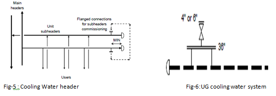
At the end of each unit sub-header, a flanged connection should be foreseen, to permit the commissioning of the sub-header by installing a temporary bypass between the supply and return sub-header. The size of the connection is to be defined to comply with commissioning requirements (See Figure 5). If the size of the bypass is similar to the main header the flanged connection could be installed in place of the piping bottom.
If the CW network is located underground with large headers size, manholes (36”, 900 mm diameter) are required for the inspection and maintenance of pipes. Manholes are normally placed close to the beginning and to the end of each header and sub-header and along with the headers at a fixed distance (every 200-300 meters) according to contractual requirements. A manhole can be provided with an additional 4” or 6” valves on top, to permit venting during start-up (Figure 6). A note will be added on P&IDs.
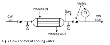
Flow control of cooling water:
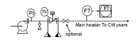
As a result of CW circuit verification, some cooling water users could receive less water than required. Other users, instead, receive a flow rate higher than required. Therefore an adjustment of the water distribution is necessary. Some users can have their own control valve on the cooling water side, in order to regulate the CW flow as required by the different working conditions. CW users without a control valve may have manually adjustable piping valves (butterfly type), on the inlet and outlet line to throttle the flow when required (Figure 7).
Fig. 7: Flow Control of Cooling water
The valve to be throttled is the one provided on the outlet line, close to the temperature indicator. If necessary, also a valve on the inlet line can be used.
Cooling water users with control valves
A control valve on the CW side of a single user is used to regulate the CW flow. Control valves shall be installed only if necessary when big differences among consumptions cases of H&MB are expected, i.e. when a precise adjustment of the duty is required. Examples are amine trim coolers, vacuum packages, columns overhead condensers, and cycle gas coolers. Column overheads are often critical because too much cooling duty could bring the column under vacuum conditions due to excessive condensation.
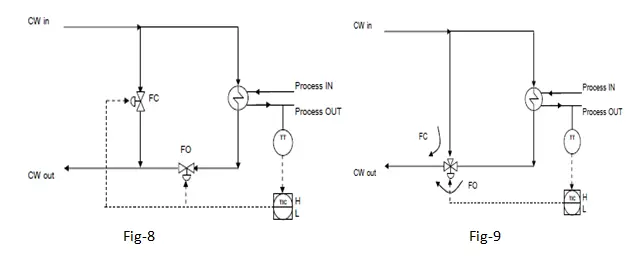
The valve controller is often a temperature transmitter located on the process outlet side of the exchanger. Throttling directly the CW flow in line can compromise the fluid dynamic of the circuit, above all if the consumption is high, compared to the pump design flow. On the other hand, if one case of H&MB uses a very low flow rate, large lines with low flow suffer from solid deposition due to low velocity. Also, CW return temperature higher than the acceptable limit could be originated emphasizing the above effects. In this case, it is better to install a bypass line around the user and to divert a part of the fluid towards the bypass, regulating CW through the exchanger, without decreasing the total flow in the lines. This measure avoids also low-velocity problems. The bypass can be sized for the total flow, in case a shutdown of the item is foreseen without complete closure of the lines with trapped water inside. Otherwise, the bypass line will be sized for the flow difference between higher and lower consumption cases.
Two configurations are possible:
Fig-8: Two control valves, one on the bypass and one on the exchanger line Fig-9: One three-way valve on the outlet side of the exchanger, to make Cooling water mixing easier
The failure position of the valves shall be always selected in order to let the CW flow through the exchanger,
in order not to have CW failure. For a column overhead condenser, pay attention to the possible vacuum condition, when the failure position is open. Fail Last position (FLO, or stay-put) could be preferred.
Cooling Water System Control
Cooling water pumps normally do not have control valves on the discharge line. There is no need to set a flow through the main header; the only requirement is to provide the necessary cooling water flow for each user.
Even the pressure is not normally regulated; it depends on the network fluid dynamic and on the return point pressure.
For the pump minimum flow line, It has to be evaluated if a stop-check valve on the discharge of the pump has to be installed; this valve facilitates start, stop, and avoids surge events due to rapid check valve closure time during an emergency shutdown. This valve shall be added to the pump Vendor’s scope of supply. A note on the pump datasheet and P&ID should be added, for example: “Non-return valve complete with power actuator, auto-closure control, hand operating gear, position indicator, and terminal box. Supplied by pump Vendor.” This non-return valve normally acts as an isolation valve too; if required by the Client, another isolation valve can be added downstream (Figure 10). As an alternative to the integrated stop-check valve which combines two functions, it is possible to consider the solution that consists of the provision of an independent check valve (dual flap-type) and a motorized valve.
Fig-10 Cooling water system Control
Automatic start-up of the spare pump shall be provided to overcome the temporary partial lack of CW when an operating pump has a failure. Start-up should be provided with a low-low pressure actuation, more often than a flow actuation; this is to avoid starting off the spare pump during a blocked outlet condition, with zero flow and high pressure. Pump start-up will be specified with the discharge valve closed only if the stop check valve is present downstream.
A plot plan is a key engineering document of the engineering phase. The plot plan schematically locates the equipment layout, the position of roads, buildings, support infrastructures, and other constructions inside an industrial plant with their dimensions and distances in between. The plot plan is a vital document as it serves as the basis for establishing the sequence of major engineering and construction activities.
Plot plans are usually initiated in the pre-contract, conceptual, and development stages of a proposal. During the detailed engineering phase, as the project progresses, they are developed with proper information and dimensions. Even though the plot plans are used by every engineering group, the plot plan is developed by the plant piping layout engineers/designers. The plot plan is a dynamic document and keeps evolving throughout the project life.
Definition of a Plot Plan Drawing
A plot plan drawing can be defined as a master plan drawing locating each unit/facility within the plot boundary. It shows the arrangement of equipment and supporting facilities to integrate any process within a common battery limit area. The plot plan drawing usually identifies all items using proper number designation and draws the basic shapes to the scale. It basically provides a bird’s eye view of the full property.
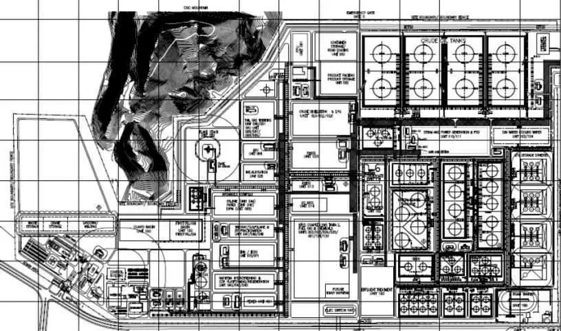
Fig. 1 below shows an example of a typical plot plan for a plant.
Fig. 1: Plot Plan Example
Applications of Plot Plan Design
The applications of a plot plan are manifold. The plot plan document is by all engineering departments executing the project for various purposes as listed below:
The piping team uses the plot plan drawing to produce equipment arrangement studies, optimize the pipe and equipment route philosophy within a limited area, and get an initial estimate of piping material quantities.
The civil team uses the plot plan to develop foundations for support design, grading, drainage plans, diked areas, holding ponds, structural designs, and all bulk material estimates for preliminary design.
The electrical engineering team uses the plot plan for locating substations, switchgear, motor control center, etc to cable routing and to have a preliminary estimate of bulk materials.
The instrumentation team utilizes the plot plan for deciding the location of the main control house, analyzer houses, and cable trays and to get a rough estimate of bulk materials.
The plot plan is used by process engineers for initial hydraulic design, line sizing, and utility block flow requirements.
The planning and Scheduling team uses the plot plan to plan and schedule the orderly completion of the engineering design.
Throughout the entire construction phase, the construction team uses the plot plan to study and determine the erection sequence of all equipment, constructibility reviews, and laydown areas.
Project and Estimation engineers use the plot plan is used to determine the overall cost of the project.
And finally, the client uses the plot plan to perform safety, operation, and maintenance reviews and to develop an as-built record of the plant arrangement.
Plot plan drawings are key documents to assess fire protection and are thus used as an essential document for permits and determining environmental and personnel safety.
Types of Plot Plan Drawings
In general, a plot plan for any project is divided into two groups:
Overall Plot plan for all the units of the project combined and
Unit Plot Plan for each separate unit.
However, there are various other terms that are sometimes used to provide an example of plot plans like:
Proposal plot plan for establishing the bid document.
Sectional Plot Plan where the plot plan is broken down into manageable-sized drawings.
Planning plot plan to start initial work by all engineering teams.
Production plot plan as the basic document for detailed design work.
Construction plot plan to start erection and construction work at the site.
As-built plot plan in the final plot plan reflecting the completed project as constructed.
Inputs Required for Plot Plan Development
Plot Plan development is very important to produce a safe, cost-effective operational plant. Plot plans are developed in stages as and when updated information is available. Developing an error-free plot plan requires knowledge of plant layout requirements, maintenance, and operational access requirements. Various inputs are required during plot plan drawing development. Some of those inputs are:
Block flow diagram indicating interconnecting lines between storage facilities, process plants, and utility plants.
Specifications indicating clearances, spacing, access, and maintenance requirements.
Existing site map mentioning geographic details like plant elevation datum, reference coordinates, weather conditions, available real estate, road, railroad, river, and land contours, etc.
Preliminary size/drawing of each piece of equipment.
Requirement of critical piping materials.
Preliminary civil drawings for structures and buildings.
Preliminary pump house, compressor house, substation, and control room layout.
Condition-based maintenance (CBM) has emerged as a transformative approach in the oil and gas industry, shifting the paradigm from traditional preventive maintenance to a more intelligent and data-driven strategy. As operators strive to improve efficiency, reduce downtime, and minimize costs, CBM offers a way to align maintenance activities with the actual condition of equipment.
What is Condition-Based Maintenance?
Condition-based maintenance, or CBM, is a proactive maintenance strategy to monitor the equipment performance and maintenance needs using real-time data. CBM, or condition-based maintenance, identifies the state of the asset by sensor-collected real-time data. When the data warns that the machine condition is unsatisfactory, maintenance is performed. Condition-based maintenance avoids unnecessary time-bound maintenance tasks and maximizes productivity by reducing downtime.
Key Components of CBM
CBM leverages real-time data to optimize maintenance interventions. The key components of a condition-based maintenance strategy are:
Condition Monitoring: The continuous or periodic measurement of various parameters (e.g., vibration, temperature, pressure, and acoustic emissions) that indicate the health of an asset.
Data Analysis: The processing and analysis of condition monitoring data to identify trends, anomalies, and potential failures.
Decision-Making: Utilizing data insights to inform maintenance schedules, thereby minimizing unnecessary interventions.
Feedback Loop: Continuous improvement through feedback mechanisms, ensuring that maintenance strategies are adapted based on performance outcomes.
Condition-based maintenance philosophy decides the equipment condition by:
Visual inspections
Various NDT tests
Real-time data gathered by sensors.
Working Principle of Condition-based Maintenance
Condition-based maintenance works using the following three simple steps:
Capturing sensor data,
Communicating data, and
Performing maintenance work.
Capturing Sensor Data
In this stage of the Condition-based maintenance philosophy, various non-destructive tests are performed using condition-monitoring sensors. Such sensors check the conditions of the machine. The main parameters that are checked during the equipment’s working condition are vibration, temperature, pressure, etc. Some of the widely used condition-monitoring sensors include:
Accelerometers: They measure vibration, velocity, and displacement.
Infrared Cameras: They can detect heat and display results on a thermal image.
Fluid Condition Sensors: These tools observe the fluid condition.
Tank Level Sensors: These sensors check and monitor the fluid level in a tank.
Pressure Transducers: They measure fluid pressure. (Both liquids and gases)
Ammeters: They gauge the current running through a circuit.
Ferrography
Communicating Data
When a CBM sensor finds any monitored parameter out of its operating range, it must be communicated properly to a technician for remedial action. The communication may be in any form like an alarm, message, PLC, HMI, or SCADA.
Performing Maintenance Work
Once the sensor-monitored data creates a notification the maintenance team is alerted for fixing the problem. A work order is created and the maintenance of the equipment is performed.
Benefits of Condition-based Maintenance
Condition-based maintenance provides various advantages like:
Optimized Time Spent on Maintenance, Over maintenance is eliminated.
Increase plant efficiency by correcting performance-affecting issues.
Less Disruption of Production.
Increase employee safety by confirming the equipment is in good condition.
Lowered Chance of Catastrophic Failure.
Reduced Asset Downtime.
Increased profitability.
Improves worker safety.
Improve reliability and ROI for equipment.
Reduces the possibilities of collateral damages.
Quicker problem diagnosis.
The Importance of CBM in the Oil and Gas Industry
The oil and gas industry operates in highly demanding environments where equipment reliability is crucial for operational success. Factors such as extreme weather conditions, corrosive materials, and high-pressure operations increase the likelihood of equipment failure. By adopting CBM, operators can achieve several key benefits:
Reduced Downtime: Timely maintenance based on actual conditions reduces unplanned downtime.
Cost Efficiency: Minimizing unnecessary maintenance activities saves money and resources.
Enhanced Safety: By ensuring equipment is maintained based on its condition, the risk of catastrophic failures is lowered.
Extended Asset Life: Regularly monitoring equipment conditions can identify issues before they lead to significant damage.
Condition-based maintenance in any plant can be implemented as follows:
Identify your critical and expensive equipment that may cause serious loss or risk.
Determine the most appropriate tools to detect equipment degradation or failure possibility.
Set thresholds to trigger CBM alerts when there is a deviation in data from the normal condition.
Manage and organize the data.
Appoint the right person who can take necessary action based on the data.
The major steps for CBM implementations can be described as follows:
Step 1: Establish a Baseline
To effectively implement CBM, organizations must first establish a baseline of normal operating conditions. This involves collecting data over time to understand how equipment behaves under typical operational parameters.
Step 2: Select Appropriate Sensors
Choosing the right sensors is critical for effective condition monitoring. Factors to consider include the type of equipment, environmental conditions, and specific failure modes to monitor.
Step 3: Data Collection and Integration
Data should be collected continuously or at specified intervals and integrated into a centralized system. This allows for real-time monitoring and historical analysis.
Step 4: Analysis and Decision-Making
Advanced analytics and machine learning techniques can help identify patterns and predict failures. This requires skilled personnel who can interpret the data and make informed decisions.
Step 5: Continuous Improvement
Feedback from maintenance activities should be used to refine the CBM strategy continuously. This involves reviewing performance metrics, adjusting maintenance schedules, and updating sensor configurations as needed.
Types of Condition-based Maintenance
There are various types of CBM techniques. Some of the most widely applied condition-based maintenance examples:
Vibration Analysis for rotating equipment like pumps, turbines, and compressors.
Acoustic testing for detecting leakages.
Operational Performance to detect temperature, pressure, flow rate, etc.
Electrical Checking to detect current reading, voltage, etc.
Infrared thermography to find high-temperature conditions.
Oil analysis to analyze oil health, contamination, and machine wear.
Disadvantages of Condition-based Maintenance
There are some drawbacks of condition-based maintenance:
The significant initial cost to perform criticality analysis and sensor placement.
Training of associated personnel.
Software requirements to handle the massive data from sensors.
Uniform wear failures may not be detected sometimes.
Unpredictable maintenance period.
Differences between Condition-Based Maintenance and Time-Based Maintenance
Time-Based Maintenance (TBM) is a maintenance strategy that involves performing maintenance activities at predetermined intervals, regardless of the actual condition of the equipment. This approach is based on time schedules, such as daily, weekly, or monthly maintenance tasks, aimed at preventing failures and ensuring operational continuity. While TBM can simplify maintenance planning and execution, it may lead to unnecessary maintenance work, increased costs, and potential inefficiencies, as interventions occur without regard to the actual performance or condition of the equipment.
Here’s a comparison table highlighting the key differences between Condition-Based Maintenance (CBM) and Time-Based Maintenance (TBM) in the context of the oil and gas industry:
Aspect
Condition-Based Maintenance (CBM)
Time-Based Maintenance (TBM)
Definition
In a condition-based maintenance strategy, the maintenance is performed based on the actual condition of the equipment.
In a time-based maintenance strategy, the maintenance is performed at predetermined intervals regardless of equipment condition.
Approach
Data-driven; relies on real-time monitoring and analysis.
Schedule-driven; based on fixed timelines.
Cost Implications
Potentially lower long-term costs due to reduced unplanned downtime.
Higher costs due to scheduled maintenance that may be unnecessary.
Downtime
Reduced unplanned downtime through timely interventions.
Higher risk of unplanned downtime due to unexpected failures between maintenance intervals.
Efficiency
More efficient use of resources by maintaining equipment only when needed.
Less efficient; may result in over-maintenance or under-maintenance.
Data Requirements
Requires extensive data collection and analysis.
Minimal data requirements; based on time schedules.
Flexibility
Highly flexible; maintenance schedules can be adjusted based on real-time data.
Rigid; maintenance schedules are fixed and may not accommodate unexpected conditions.
Safety
Enhances safety by preventing equipment failures through timely maintenance.
May compromise safety if equipment fails unexpectedly between maintenance intervals.
Asset Lifespan
Can extend the lifespan of assets by addressing issues before they escalate.
May not optimize asset lifespan due to maintenance performed regardless of actual condition.
Implementation
Requires investment in sensors, monitoring systems, and analytics tools.
Easier to implement as it follows a straightforward schedule.
Skills Required
Requires skilled personnel for data analysis and interpretation.
Requires less specialized skill; focuses on routine maintenance tasks.
Application Examples
Monitoring blowout preventers (BOPs), pipelines, and gas turbines.
Routine inspections and maintenance of non-critical equipment based on a fixed schedule.
Table 1: Condition-based Maintenance vs Time-based Maintenance
This table summarizes the fundamental differences between CBM and TBM, illustrating why CBM is often favored in the oil and gas industry for its ability to enhance efficiency and safety while reducing costs.
Condition-based maintenance is revolutionizing the oil and gas industry, enabling companies to enhance reliability, reduce costs, and improve safety. By leveraging real-time data and advanced analytics, organizations can optimize their maintenance strategies, leading to more efficient operations.
Pressure is perhaps the most crucial control variable in a distillation column. This variable affects condensation, composition, volatilities, and any process that happens in the column. A distillation column will not achieve smooth operation unless a steady pressure can be sustained.
Normally, column pressure control is integrated with the condensation system. So, condensation control and pressure control need to be considered simultaneously.
Some general guidelines are given here for pressure and condensation control,
The overhead stream should enter the reflux drum at a lower velocity so that it prevents disturbances to the surface of the liquid.
Vapor bypass piping & equalizing line should be self-draining and should consist of no low points where condensate can be accumulated.
For higher condensing temperatures and a narrow condensing range, condensation on the reflux drum walls may affect condensation and pressure control. Then vapor space insulation of the reflux drum should be considered.
The pressure-equalizing line should be sized for a minute pressure drop. As a rule of thumb, equalizing the line with 20 percent of the cross-section of the column overhead vapor line is adequate enough to control unbalanced pressure.
Pressure Control in Atmospheric Column
For atmospheric distillation, column pressure is controlled by having the column open to the atmosphere. By varying the airflow in and vent gas out of the column through the column vent. If the air ingression into the system is undesirable, an inert purge is done at the vent.
If the column is open to the atmosphere, the rate of condensation can be often controlled by the level is present in the reflux drum or by the temperature of the reflux drum.
Different Pressure Control Techniques
There are four techniques through which pressure can be controlled in a distillation column.
Vapor flow variations
Flooded condensers
Coolant flow variations
1. Vapor Flow Variations:
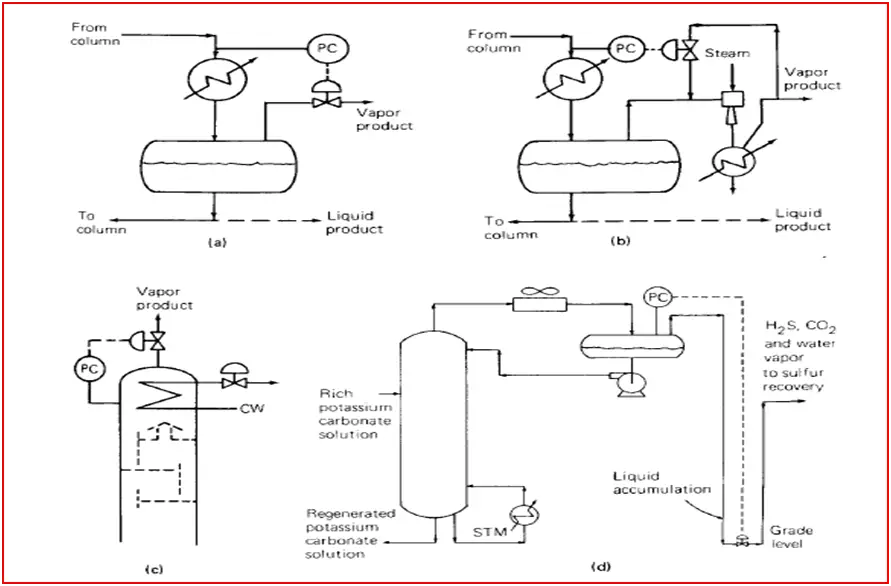
If the column has a vapor product the controller directly manipulates the vapor flow (Fig-1a) so that pressure can be controlled. This method is normally used for vacuum columns (Fig-1b), the pressure controller varying the quantity of spillback to the ejector suction. The spill-back control method can also be applied to the pressure columns where the vapor product is compressed. In the schemes shown in Fig-1a & 1b, the rate of condensation is usually manipulated by the accumulator level. For the stacked condenser shown in Fig-1c, condensation rate control is more difficult.
Fig. 1: Different types of overhead systems.
Appropriate piping of the vapor product line is imperative to the success of the above control method. As per Fig-1d, if there is a low leg in which liquid can be accumulated due to entrainment or atmospheric condensation; backpressure can be caused to the column that may interfere with the pressure control.
2. Flooded Condenser:
This pressure-controlling method is one of the best methods for a total condenser system. Some of the condenser surfaces are flooded with liquid always. The flow of condensate from the condenser is directly or indirectly controlled to vary the flooded area. In the flooded area, heat transfer is very low as heat is transferred by sensible heat exchange only. To increase the distillation column pressure, the flow of condensate from the condenser should be less. This low rate enhances the flooded area in the condenser and reduces the surface area exposed to vapor condensation. This results in a reduction of the condensation rate, thereby raising the pressure of the distillation column.
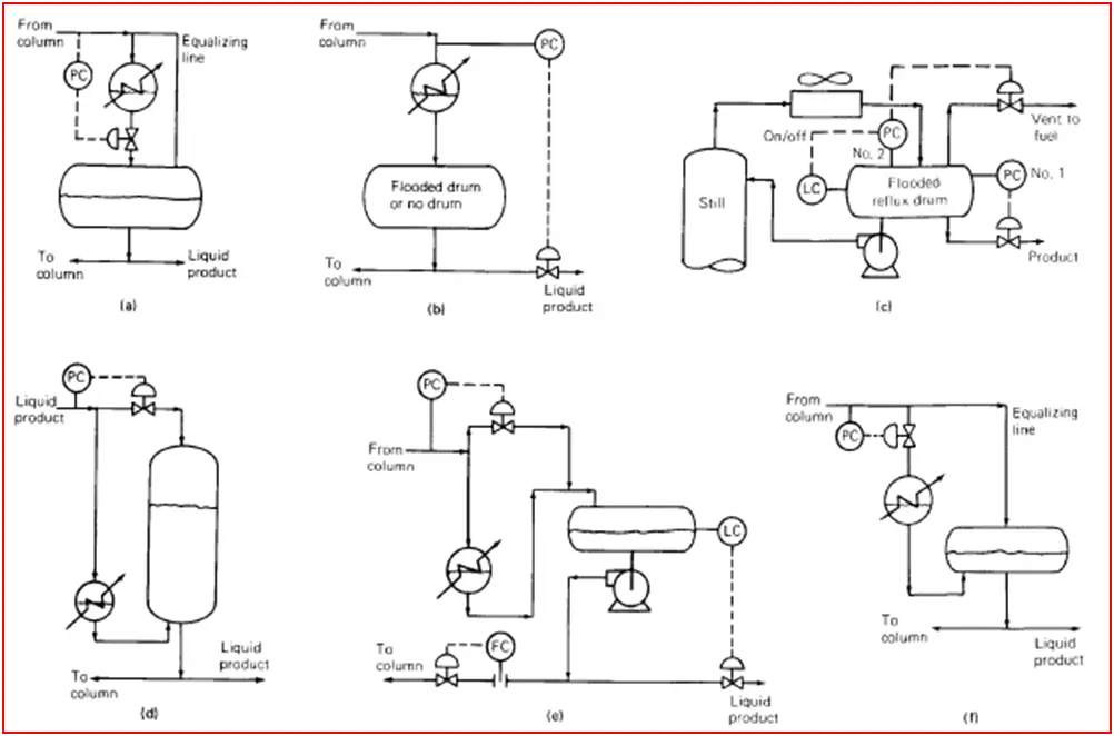
Fig-2a shows a flooded condenser associated with a control valve installed at the condenser outlet. The control valve required is small and should be located as close to the reflux drum as possible to achieve maximum static head. This method is very simple to arrange, linear & maintains the same pressure in the column and reflux drum. So this method is often favored.
The outlet pipe of the condenser may enter the reflux drum either above or below the liquid level. In some cases, it is above the liquid level of the reflux drum so that changes in the level cannot impact the condenser level. Besides, the entry point can be below the liquid level so that cold liquid is introduced at the bottom of the reflux drum. As well as it provides a better seal to the condenser that avoids gas blow-by scenarios through the condenser.
Fig. 2: Various overhead systems
If the sub-cooled liquid is introduced above the liquid level, the vapor above the liquid level may collapse when it meets the liquid resulting in pressure variation.
Pressure-equalizing Line:
The pressure equalizing line plays an important role in this type of control. It helps to maintain a steady pressure through balancing pressure variations. The pressure at the reflux drum may be unsteady without this line. This line should be sized for a minute pressure drop. Normally, the size pressure equalizing line is between ½’’ to 2’’.
Fig-2b illustrates the flooded reflux drum method. This method directly controls the distillate flow. This type of control method usually is avoided for unsteady control unless the product goes to storage.
Fig-2c illustrates an automatic vent system where a secondary pressure controller PC No.2, a level controller, and a control valve are present in the vent line. The setpoint of PC No.2 is normally lower than that of the normal pressure controller (PC No.1). If the drum is full, the level controller keeps PC No.2 tripped off and closes the vent valve. During drum unflooding (due to accumulation of non-condensable) is sensed by a decrease in drum level. The lower activates PC No.2. Since the set point of PC No.2 is closed, helping to build up the drum level. As soon as the drum refills, the level controller trips PC No.2 and closes the vent valve.
Unless the product is sub-cooled & at a significantly higher pressure than storage, it is best to take the product to storage from downstream of the reflux pump. If the product is taken from the drum as per Fig-2c, flashing may occur downstream of the control valve.
Fig-2d shows pressure control by a hot vapor bypass. The condenser is located below the liquid in the drum (horizontal/vertical). The condensate must be sub-cooled so that the liquid surface in the drum is cooler than in the condenser. This causes a difference in vapor pressure large enough to transport condensate from the condenser into the drum.
If the column pressure rises, the pressure controller closes the valve. This reduces the condensation at the drum surface and lowers the drum surface temperature and therefore the drum vapor pressure. It enhances the vapor pressure difference between the condenser and the drum, which in turn forces more liquid out of the condenser and into the drum. This exposes additional condensing surfaces in the condenser and increases the condensation rate.
The advantage of hot vapor bypass arrangement has that advantage of eliminating the need for a condenser support structure easy access for maintenance, a small control valve & fast response. This advantage can translate into major savings in steelwork, platforms, etc.
Correct piping is necessary for the hot vapor bypass line method. Bypass vapor must enter the vapor space of the reflux drum (Fig-1d). The bypass line should be free vapor pockets where liquid can accumulate. If non-condensable are likely, vents are required on the condenser and drum. The condenser vent can be directed to the vapor space of the drum.
In the fig-1e scheme, sub-cooled liquid mixes with dew point vapor. The collapse of vapor takes place at the point of mixing. The rate of vapor collapse varies with the change in subcooling, overhead temperature, and condensation rate. Pressure can fluctuate with the rate of change of the vapor collapse rate. This problem can be ruled out by separating the liquid line from the vapor line and extending the liquid line well below the liquid surface. The vapor line entered the previous inlet.
Fig-2f shows a flooded condenser scheme to that of Fig-2a but with the control valve located at the condenser inlet. This method is inferior compared to Fig-1a. This control method requires a larger control valve, is more difficult to understand and it affects condensation at the lower temperature. The condenser outlet line must enter the reflux drum well below the liquid level. A pressure-equalizing line as in the method shown in Fig-2a is also required. In addition to the above limitations, this method is also prone to liquid hammering if the valve excessively closes.
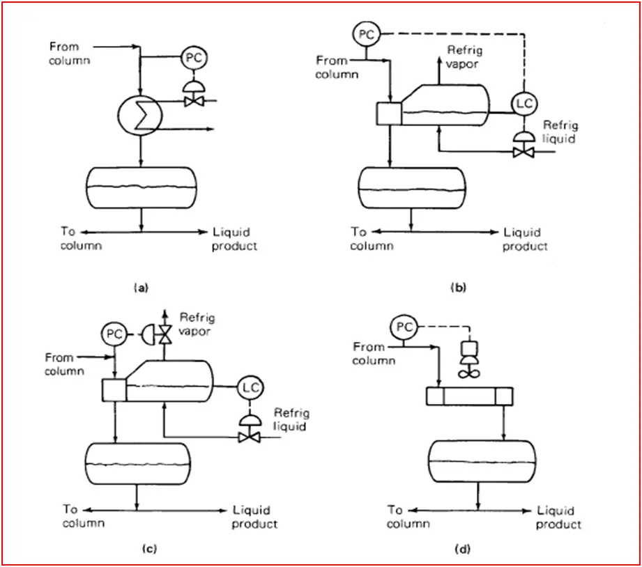
3. Coolant Flow Variation:
Fig. 3: Different types of overhead systems.
Fig-3a shows an arrangement used with cooling water flow rate variation. This method promotes fouling, and slow response particularly when low-flow operation, when cooling water velocity is low & exit temperature is high. Besides, very low velocity may also lead to freezing during winter. It is recommended to keep the water temperature 120-1300F at the condenser outlet all the time as well as cooling water velocity to be maintained more 3-5 ft/s.
Fig-3b arrangement used with refrigerated condensers. The condenser is a kettle reboiler, boiling refrigerated liquid.
Fig-3c shows an alternative arrangement where the refrigerant level is above the condensing tubes and control column pressure by manipulating a control valve in the refrigerant vapor line. This method is prone to liquid carryover from the condenser, especially if the refrigerant side pressure suddenly drops.
Fig-3d shows a coolant variation arrangement for air condensers. This arrangement is energy-efficient and minimizes fan power consumption.