Cryogenic plants play a vital role in the production and processing of gases at extremely low temperatures, such as liquefied natural gas (LNG), liquid oxygen (LOX), and liquid nitrogen (LIN). At the heart of these facilities lies a crucial component known as the “cold box.”
What is a Cold Box?
A cold box is a specialized enclosure that houses key cryogenic equipment, such as heat exchangers, distillation columns, and other components necessary for the liquefaction and separation of gases. Its primary purpose is to maintain low temperatures while minimizing heat transfer from the external environment, ensuring optimal performance of the cryogenic processes.
Key Functions of a Cold Box
- Thermal Insulation: The cold box is designed with advanced insulation materials to reduce heat ingress. This insulation is critical to maintaining the extremely low temperatures required for cryogenic operations.
- Separation and Liquefaction: Inside the cold box, the gases undergo processes like distillation and heat exchange. The design facilitates the efficient separation of different components based on their boiling points.
- Safety Containment: The cold box also provides a safe environment for operating cryogenic processes. It is equipped with safety features to handle pressure fluctuations and prevent leaks.
- Condensation and Phase Change: The cold box allows for the condensation of gases into liquids, which is essential for transporting and storing cryogenic fluids.
What is a Cold Box in an Air Separation Unit?
The cold box in an air separation unit is a highly engineered large rectangular box enclosing the major cryogenic equipment. Some suppliers use a round silo design in which the equipment is primarily supported by the cold box foundation. The cold box wall is made up of steel panels that are welded onto the cold box frame. The space between the cold box wall and the equipment is filled with insulating material.
The cold box frame and foundation are designed to support the weight of all process equipment, as well as piping and valves containing the maximum operating level of liquid. It must also withstand high wind loadings as required by national codes and be suitable for the earthquake zone in which it is installed.
In air separation plants you can see square columns installed. Those are actually cryogenic cold boxes used to minimize heat leakage to the environment. The temperature inside the cold box is usually in the range of -196 Deg C. To prevent heat transfer vacuum is used.
Insulating Material used in Cold Box
The insulation material used in a cold box is either perlite, a fine powder, or slag wool, similar to glass wool but denser.
Typically, perlite is used for insulating the bulk of the cold box where access is unlikely to be required. Slag wool is used in areas where access may be necessary as it can be removed more easily than perlite. Slag wool is typically used in turbine, pump, and valve boxes.
Equipment housed in a Cold Box
The common equipment housed within the cold box typically includes:
- distillation columns
- heat exchangers
- separators
- cryogenic adsorbers
- piping and valves
- the cold end of the turbine
The equipment associated with the cold box typically includes:
- adsorbers
- cryogenic pumps
- expansion turbines.
Access to the internal equipment of a cold box is not possible during operation. Hence, all equipment functions are controlled through valves with extended stems that pass through the cold box wall. Access to the valves in a cold box for operation and maintenance is usually provided by a series of linked platforms and stairs or ladders.
Why does water cause a hazard to the Cold Box?
Water entering a cold box will freeze. It can become a hazard by preventing piping from free movement or causing excessive weight loads.
Ice may greatly extend the time required when a cold box is thawed. Therefore, it is extremely important to maintain the integrity of the seal at an opening (for example, at the valve and piping seal boots and manways). Water should be prevented from pooling on any horizontal surface.
Cold Box Purging
If the space inside the cold box contains air then oxygen could condense on liquid nitrogen pipework and create a hazard, also moisture can form ice in the perlite or slag wool, reducing the insulation and making it difficult to remove.
The insulation space inside the cold box is filled with nitrogen for this reason. This is known as the cold box purge. The cold box purge must be maintained whenever the cold box equipment is at cryogenic temperatures. It is usually maintained at other times also, except during internal work on the cold box equipment.
Different Types of Piping Involved in Cold Box
There are four types of piping involved in a cryogenic cold box:
1. Process piping
The process piping is used to carry fluids between the equipment items. Process pipes in a cold box vary in size from the very large low-pressure waste piping (up to 36 inches (0.9 m) on a large tonnage ASU) to small liquid lines such as liquid argon product (1 inch, 25 mm). Click here to know more about Cryogenic Piping.
2. Relief Valve Piping
The Relief valve piping connects pressure vessels to external pressure relief Valves. The major pressure relief pipes are for the high-pressure and low-pressure columns. These may have to handle large flows of gas with small pressure drops and can therefore be large in diameter. They must discharge to safe locations because of the potential for very high oxygen or nitrogen concentrations and low temperatures and are typically routed to the top of the cold box.
3. Vent, Drain, Purge Piping
Purge, vent, and drain piping which connects process equipment and process piping to the outside of the cold box for the supply of services, such as dry air or N2, and to allow venting of process gases or purge gases to the atmosphere.
These pipes are typically in the range of 4 to 1 inch (100 to 25 mm) in diameter. Purge and drain connections are usually found near the base of the cold box and maybe in groups connected to headers. Purge connections to process piping are made to the top of horizontal lines or to the side of vertical lines. For process pipes that can contain liquid, the thaw line must have a vertical lute of at least 1.5 ft (500 mm) to provide a vapor seal and prevent the backflow of liquid to the purge system.
Whenever possible, thawing and drain lines are run close to the cold box face to gain heat to maintain a warm gas seal to the valves. The liquid drain headers are connected to safe liquid disposal areas. The exhaust plume from vent piping may be O2 enriched or depleted. Vents must be located so that personnel cannot enter the plume until it has mixed with sufficient air to reach a concentration in the range of 19 to 25% O2.
Drains and vents may discharge liquid or very cold gas and must be positioned so that personnel is protected from contact and that discharge flows do not impact temperature-sensitive material and equipment.
4. Instrument piping
Instruments are connected from outside the cold box through the cold box face to the equipment items and the process piping by instrument piping. Instrument piping may also be known as impulse lines. The term instrument (for example, pressure, analysis, flow) tap also designates the connection from the valve at the cold box face to the internal process equipment.
Instrument piping is small-bore since flows are typically very small (to analyzers), or zero (for pressure, level, and flow instruments). The minimum size is determined by practical requirements for strength to withstand loads imposed by movement due to shrinkage or manual loads during cold box manufacture and maintenance.
Instrument connections are grouped at the cold box face into panels. This is for allowing easy access to both permanent and temporary instrument connections.
Why warm seal is provided in the cold box safety valve line?
To prevent relief valves from being permanently cold a warm gas seal is created on the piping. The piping runs vertically upwards from the box penetration by at least 750 mm (2.5 ft). Where feasible, the line within the cold box is routed close to the box face prior to the box penetration.
What material is used for piping?
Piping is usually manufactured from aluminum, although stainless steel and copper alloys are used in some services. All three materials remain ductile at cryogenic temperatures. Carbon steel is not used because it becomes brittle and may fail at temperatures below –29°C.
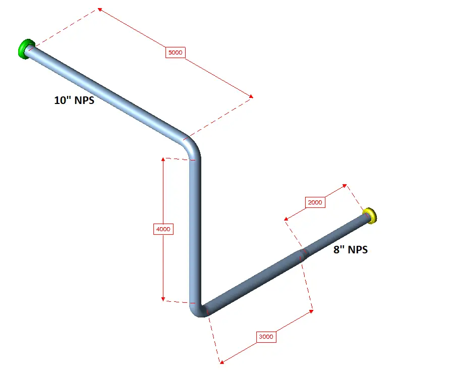
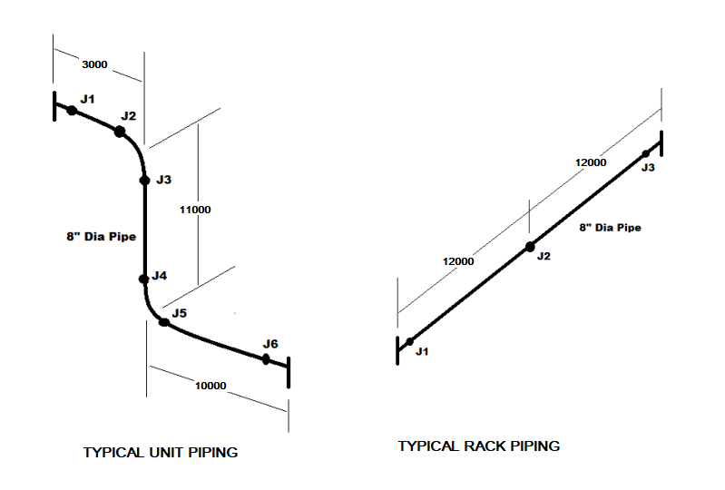
Why does a cold box require flexibility? How is the flexibility provided?
Equipment in a cold box shrinks when in operation. For example, the height of a 60-meter (197-ft) high distillation column may shrink by approximately 230 mm (9 in) when cooled to operating temperature. All the piping attached to the equipment must accommodate this shrinkage. Flexibility is provided by a series of turns in the piping, usually by a sequence of vertical and horizontal sections.
Supporting Cold Box Pipes
The long lengths of piping in a cold box require support at regular intervals. Various types of support are used which either provide a fixed anchor or allow controlled movement.
- Horizontal runs of large pipes may have spring-assisted supports to allow controlled movement.
- Vertical pipe supports may allow sliding movement.
What safeguard follows to minimize leaks inside the cold boxes
Once equipment and piping have been insulated, access for any repairs becomes extremely
expensive. To minimize piping leaks, all piping joints in the perlite region of a box are welded. Special transitions are required for any unavoidable transition joints between incompatible metals (for example, aluminum to stainless steel). Where it becomes absolutely necessary to use flanges connections, these are placed in a separate internal box which is insulated with slag wool. This allows access without having to remove the perlite from the larger cold box.
How does Cold Box Accommodate Shrinkage?
Shrinkage of vessels and piping in operation causes movement of piping and valves relative to the cold box surface. The amount of movement increases with box elevation. This movement is accommodated by a flexible rubber boot placed between the box face and the valve stem.
Valves in Cryogenic Service
Valves used in cryogenic service have the same functions and duties as in any other process service but have some additional requirements for operation at low temperatures. Special requirements related to materials of construction and installation.
The valve body is contained within the cold box, with the stem extending through the box wall. Both stem and bonnet are usually manufactured from type 304 or 316 stainless steel, which has the necessary strength coupled with low thermal conductivity. The bonnet is an integral part of the valve body, with the stem seal located at the warm end of the extension external to the cold box
The type of cryogenic valve used is determined by service needs such as range of control, and allowable leakage when closed but may also be limited by practical issues such as weight and availability.
- Cryogenic globe valves are typically used to a diameter of 150 to 200 mm (6 to 8 inches).
- Butterfly valves are used for larger services.
Design Considerations
The design of a cold box is complex and requires careful consideration of various factors:
- Materials: The materials used in constructing a cold box must withstand low temperatures and high pressures. Common materials include stainless steel, aluminum, and specialized alloys.
- Insulation Technology: Multi-layer insulation (MLI) or vacuum insulation techniques are often employed to achieve the required thermal efficiency. These methods minimize heat transfer and keep the internal environment stable.
- Size and Layout: The dimensions and configuration of the cold box depend on the specific applications and the volume of gases being processed. Proper layout ensures efficient flow and minimizes dead spots where heat could accumulate.
- Safety Features: Given the risks associated with cryogenic materials, cold boxes are equipped with safety relief valves, pressure monitoring systems, and emergency shutdown mechanisms.
Applications of Cold Boxes
Cold boxes are used in various industries, including:
- Natural Gas Processing: In LNG plants, cold boxes are essential for liquefying natural gas, allowing for easier storage and transportation.
- Medical and Pharmaceutical Industries: Cold boxes play a role in producing liquid oxygen and nitrogen for medical applications, ensuring the safe delivery of critical gases.
- Aerospace and Defense: Cryogenic technologies are vital in aerospace for rocket propellants, making cold boxes crucial for testing and production.
- Industrial Gas Production: Cold boxes are also used in the production of industrial gases, such as argon, krypton, and xenon, through air separation processes.
Benefits of Using a Cold Box
- Enhanced Efficiency: By optimizing the conditions for gas liquefaction and separation, cold boxes significantly improve the efficiency of cryogenic plants.
- Cost-Effectiveness: Reduced heat transfer and improved thermal management lead to lower energy consumption and operational costs.
- Improved Safety: Advanced design and safety features in cold boxes minimize the risks associated with cryogenic operations, protecting both personnel and equipment.
- Space Optimization: Cold boxes can be designed to maximize space usage, allowing for more compact plant layouts while still maintaining operational efficiency.
The cold box is a fundamental component of cryogenic plants, enabling the efficient processing of gases at extremely low temperatures. Its sophisticated design, combined with advanced insulation and safety features, ensures optimal performance while mitigating risks.
More details about cryogenic valves are already covered in the following article: What is a Cryogenic Valve? Features and Applications of Cryogenic Valves