Cold cutting, as the name suggests, is a cutting operation without using heat. This is an effective cutting method used in various industries including material processing, pharmaceuticals, chemical, petrochemical, and oil & gas. In this article, we will explore more about the cold-cutting process, its definitions, reasons, benefits, and types of cold-cutting machines.
What is Cold Cutting?
Cold cutting can be defined as a material cutting procedure without using flame or heat, and without producing any spark. The cold-cutting process is one of the safest methods for cutting pipes, plates, and structures in hazardous environments.
Why Cold Cutting?
Cold cutting technology eliminates the majority of serious incidents due to the absence of heat from a torch. Heat and flame in hydrocarbon industries are serious hazards. So, the cold cutting process provides an edge in various works like pipe and pipeline repair, maintenance and shutdown activities, commissioning and decommissioning processes, etc.
Using cold cutting methods the hazards associated with thermal cutting or hot cutting are eliminated. This is the main reason that cold cutting of pipes and structural elements is ever-increasing. The main reasons for using the cold cutting procedure are:
- Safety- The absence of heat makes the cold-cutting work environment safe for the tool operators.
- Money- Cold cutting is cheaper as compared to hot cutting. Also, this can be performed in less time. So, cold cutting can easily fit into the budget.
Advantages of Cold Cutting
The cold cutting process provides a number of benefits like:
- Prevention of Heat Affected Zone resulting in improved material properties.
- Elimination of dangers associated with hot cutting. Cold cutting is safer.
- Fast and quick operation.
- Elimination of the difficult and laborious hand-grinding process to create weld ready surface makes the cold cutting operation cost-effective.
- No chance of explosion.
- No air-born contamination.
- No spark and flame.
- No hot work permit is required to start working.
Cold Cutting Machines
Cold cutting machines are the tools used for cold cutting operations. They are also known as cold cutters and usually are portable, lightweight, durable, and compact. Cold cutting machines are available in various configurations. The cold cutting technology is introduced in the year of 1949. Cold cutting machines are selected based on the application (what is to be cut), accuracy required, location, and economic viability.
Types of Cold Cutting Machines
Depending on the drive mechanism cold cutting machines are classified into the following two groups:
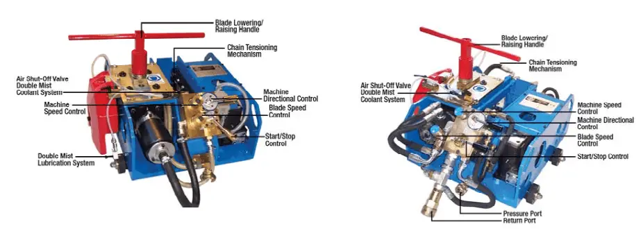
- Pneumatic or Air-Driven cold cutting machines, and
- Hydraulic cold cutting machines.
Refer to Fig. 1 below that provides a sample image of both types.
Cold Cutting Procedure Steps
The cold cutting process is usually performed following the below-mentioned steps:
Preparation for the cutting process: Using the blade lowering/raising handle, the feed screw is turned until the cutter spindle is raised to the highest position. Then the start/stop control and machine directional control are set to OFF position. The machine speed and blade control are then positioned to a fully closed position. Air or hydraulic power requirements are checked as per manufacturer requirements.
Using the cold cutting machine for cold cutting operation: The machine is now positioned properly. The wheel holders must be properly positioned to provide stability and improved performance. Next, the cutting tool is turned on for operation. The cold cutting operation must be performed by trained operators and handled carefully. The cold cutting operation is performed by the rotation of a cutter.
Types of Pipe Cold Cutting Machines
Pipe cold cutting machines are also popular as clamshell lathe, split frame cutters, clamshell lathe, or clamshell cutters. Circular in construction, pipe cold cutting machines can easily wrap around the pipe in two halves and be attached together by a hinge. The rotating cutting tool works around the pipe circumference. Depending on the size and capability pipe cold cutting machines are of three types:
- Low profile cold pipe cutter
- Mid-size pipe cold cutting machine, and
- Heavy-duty cold pipe cutting machine.
Pipe cold cutting machines perform the cutting operations for a range of pipe diameters and are suitable for precise and high-productivity requirements.
Examples of Cold Cutting Machines
There are various pipe cold cutting machines that are used for industrial applications. A Clamshell cutter is the most widely used pipe cutting tool.
Clamshell Pipe Cutter
A clamshell pipe cutter is a portable pipe cold cutting machine used for cutting and bevelling pipes. They have reduced weight and dimensions and are available in a wide range of cutters. They are suitable for cutting Steel, SS, Hastelloy, SDSS, Inconel, Alloy Steel, and Cladded pipes. Their split-frame technology can cut pipes of high thicknesses and provides various unique features like:
- Faster and Accurate process
- Complete machining system with accessories
- High-Quality precision cut
- Tracking slides for uniform land.
The main components of a cold pipe cutting machine are:
- Frame
- Split Gear
- Drive
- Ball-bearing
- Tool carriage
- Clamping feet
Some other tools that work as cold cutters are
Band Saws and Diamond Wire Saws
Widely used in chemical industries, both Band Saws and Diamond Wire Saws are used when high-precision cutting is not a requirement. They are powered by hydraulics and suitable hose and hydraulic power packs are required.
While using a band saw cold cutting machine, the cutting surface gets heated and hence suitable coolant must be used during operation.
For cutting through pipelines, piles, and caissons, Diamond Wire Saws are a good choice. A beaded rope encrusted with small diamonds on the outside surface is used for cutting in a diamond wire saw. Because of this, the name diamond wire saws are given to this cold-cutting machine. The circular cross-section of the ropes avoids the problems of compression and jamming.
Abrasive Water Jet Cutting
Abrasive Water Jet Cold Cutting is used in environments where there is a risk of fire or explosion. A very high water pressure (in the range of 4137 bar) is used in this method. A hard abrasive material is crushed into the water for the cutting operation. This method is suitable for any metal, concrete, or composite material of high thicknesses.