Nitrogen purging plays an important role in the safety and functioning of various plants that are susceptible to fire hazards. In fire and explosion protection engineering, an inert (ie, non-flammable) purge gas (like nitrogen, helium, argon, etc) is introduced into an enclosed system (eg, a container or process vessel) to prevent the formation of a fuming flammable atmosphere. This inert gas helps to mitigate the risk by overriding hazardous fire/explosion-forming agents like oxygen. In this article, we will explore more about Nitrogen purging, Its definition, procedure, benefits, etc.
What is Nitrogen Purging?
Many a time people in safety engineering ask what nitrogen purging actually means. Nitrogen purging is the process of introducing nitrogen into closed vessels, pipelines, containers, etc to displace undesirable hazardous atmospheres and to clean the inner walls. Nitrogen in the nitrogen purging process pushes out oxygen and moisture and creates a stable non-combustible environment, thus reducing the potential hazard.
Why Nitrogen Purging is Required?
Chemical Industries like acetylene production plants, Oil and Gas plants require nitrogen purging on a regular basis. The main benefits that nitrogen purging provides are:
- Nitrogen purging helps in removing the oxygen % from the internal surfaces of the pipelines and equipment. So, the possibilities of sparks and fires are greatly reduced during operation.
- Nitrogen purging removes moisture that may be present which helps in lowering the dew point.
- The nitrogen purging process ensures a safe environment for the workers and nearby residents.
- It prevents chemical alteration of the product.
Uses of Nitrogen Purging System
A lot of industrial manufacturing processes use nitrogen purging to eliminate moisture or oxygen-rich air. Introgen purging equipment is sometimes integrated with oxygen-sensitive operations to avoid unfavorable conditions. Major industrial applications of the nitrogen purging process are:
- Transformers and other volatile electrical environments enhance safety by using the N2 purging procedure.
- Nitrogen purging in the brewery industry extends the shelf life of beer.
- Ships and tankers use nitrogen blanketing to remove potentially combustible environments.
- Organic compounds generating chemical and petrochemical industries widely use nitrogen purging processes to eliminate toxic gases from process chambers.
- Atmosphere Packaging and Food industries apply the nitrogen purging process to remove moisture, oxygen, and other gaseous impurities.
- Nitrogen purging is widely used in oil and gas pipeline projects for drying, cleaning, and limiting oxygen concentrations.
- To eliminate compounds affecting weld quality, metal fabrication industries use N2 purging systems.
Why Is Nitrogen Used for Purging?
Nitrogen is dry, non-combustible, and economical as compared to other inert gases. This makes the nitrogen purging process more affordable.
Difference between Nitrogen Purging and Inerting?
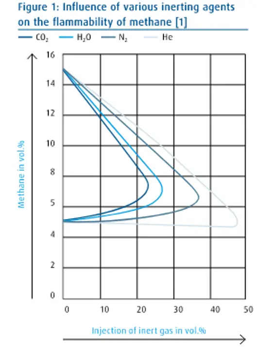
The purge gas is inert. By definition, it is non-flammable, or more precisely, non-reactive. The most common purge gases available commercially in large quantities are nitrogen and carbon dioxide. Other inert gases, eg. Argon or helium can be used. Nitrogen and carbon dioxide are not suitable for purge applications in some cases because these gases can chemically react with fine dust from certain light metals.
Since an inert purge gas is used, the purge procedure can (erroneously) be called inerting in everyday language. This confusion can lead to dangerous situations. Carbon dioxide can be considered a safe, inert purge gas. Carbon dioxide is an inert gas that is not safe for inactivation as it can ignite vapors and cause an explosion.
Difference between nitrogen purging procedures from other industrial explosion prevention methods?
Fires and explosions can also be prevented by controlling ignition sources. However, purging with an inert gas (nitrogen) provides a higher level of safety because it is guaranteed that no flammable mixture is formed. Therefore, it can be said that primary prevention is relied on to reduce the possibility of a spreading explosion, and ignition source control relies on secondary prevention to reduce the possibility of an explosion. Primary prevention is also referred to as essential safety.
Types of Nitrogen Purging Procedures
There are four main industrial nitrogen purging procedures that are widely used. They are:
- Displacement purging (Plug effect)
- Dilution Purging
- Pressure swing Purging, and
- Vacuum purging
Displacement purging (Plug effect)
In a displacement purge, an inert gas is injected into an open vessel to evacuate hazardous or noxious gases. Slow flow is maintained (velocity < 10 m/s).
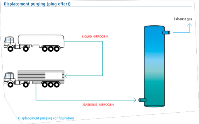
The displacement nitrogen purging procedure is mainly used for high H/D (height/diameter) ratios. Ideally, the inert gas should be denser than the displaced gas on Fig. 1 shows how nitrogen is used for the displacement purge of the vessel. Gas is transported in tankers. Liquid nitrogen is vaporized in the vaporizer and gaseous nitrogen is injected into the vessel. Nitrogen pushes the atmosphere out of the vessel through an outgassing valve. The amount of nitrogen required is relatively small, typically 1.2 times the capacity of the vessel.
Dilution Purging:
A dilution purge involves introducing an inert gas to reduce the concentration of hazardous gas.
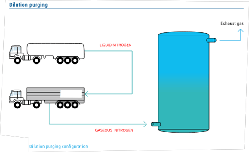
The dilution nitrogen purging procedure is used when the H/D ratio of the machine is low. The amount of nitrogen required is approximately 3.5 times the capacity of the vessel. The configuration in Fig. 2 shows how nitrogen gas is vaporized and injected into the device with the outlet valve open. The diluent gas, which consists of noxious gases and nitrogen, is released into the atmosphere or further processed.
The following equations can be used for this process:
The number of volume changes: i = ln [Ca ⁄ Ce]
The Volume of inert gas required: VN = i · VB
Here,
- i = Volume change
- Ca = Initial concentration
- Ce = Final concentration
- VN = Volume of inert gas
- VB = Volume of vessel
Pressure swing Purging:
In pressure swing purging, the closed device is sprayed with an inert gas. When the gas is released, the dangerous or harmful gas disappears. The process (closed-injection-open-exhaust) continues until the desired concentration of harmful gases in the device is reached. Variable pressure purge is used, for example, when the inlet and outlet are close to each other. The device must also be a pressure vessel. In the pumping pressure, there is a difference between vacuum purification and excessive production. One of the main goals of the pressure swing occurs due to hazardous substances or harmful substances, such as oxygen. The residual concentration of harmful substances can be calculated in the following formula:
CSR=(P1/P2)n * (CSG-CSI) +CSI
Here,
- CSR = hazardous substances residual concentration
- CSG = Concentration of hazardous substances in mixtures
- CSI = Concentration of hazardous substances in inert gas
- n = Number of pressure swings
- P1 = Pressure 1 (before inerting)
- P2 = Pressure 2 (after inerting)
Vacuum purging
Vacuum purge involves the use of a vacuum pump to remove harmful gases and then supply inert gas to the evacuated unit. This process is repeated until the desired hazardous gas concentration is reached. Vacuum purge is particularly suitable for machines with multiple dead zones.
The effective inert gas requirement is calculated as follows:
VN = VB * f * n
Here,
- VN = Inert gas requirement in m³
- VB = Vessel volume in m³
- f = Pressure change ratio
- n = Number of pressure swings
The pressure change ratio equation is as below:
f=1-(P1/P2) (P1/P2)<1
Here,
- f = Pressure change ratio
- P1 = Pressure before inerting
- P2 = Pressure following inerting
Nitrogen Purging in Pipelines
Newly laid pipeline network and sometimes after maintenance and shutdown work nitrogen purging in pipelines is performed. This process is important to remove retained moisture, oxygen, and other impurities that may otherwise change the quality of the fluid being transported.
Nitrogen purging in pipelines is a pretty straightforward procedure. Pressurized nitrogen gas is forced through pipelines that force out all gaseous and particulate impurities present inside. However, Pipeline nitrogen purging may sometimes involve risks. Hence, To safely conduct the pipeline nitrogen purging process, the operators should take the following steps:
- Ensure proper instruments/apparatus handling
- The operation must be performed by trained personnel.
- Emergency protocols for shutdown and personnel evacuation must be well informed to all.
- Personal protective equipment must be worn by all personnel involved in purging operations