The piping slope is the change in elevation with respect to its flat horizontal position. The piping slope is provided in various piping systems mainly due to free-draining requirements. A slope in the pipe helps the liquid to flow easily in the downward direction. So, it helps in avoiding the accumulation of liquid inside the piping system. This in turn helps the system to eliminate two-phase slug flow problems.
Examples of Piping Slope
There are many lines inside a complex process industry that have piping slopes. Some typical examples of pipes and equipment that are provided with slopes are:
- Underground drain piping
- Condensate piping system
- Flare headers
- Horizontal Sump Vessels (Slope in Equipment)
- KO Drums (Slope in Equipment)
- PSV outlet lines
- All piping in the main steam and hot and cold reheat line, turbine extraction system, condensate system, and turbine drains of power plants.
- Compressor suction lines between the knockdown drum and the compressor should be as short as possible, without pockets, horizontal, and sloped toward the compressor.
- Fuel-oil lines in the fuel Oil Burner piping system should be sloped from the burner shutoff valves toward the burners to provide natural drainage.
- Steam trap discharge lines should be sloped for drainage where possible.
- Drains and vents should be provided and piping sloped to facilitate liquid drainage and gas venting.
- In extensive sewer systems (except in hilly areas), most of the pipes will have mild slopes.
Piping Slope Symbol
The piping slope indicates the inclination of the pipe with respect to the horizontal ground or reference level. The application of slope in piping or pipeline systems forces the liquid to go to the next low point of the line. The requirement of the slope is usually mentioned in the process P&ID. The slope given is indicated to the construction team using piping isometrics. A special symbol is used to indicate slope in Process P&ID and Piping isometrics.
Piping Slope in Isometric
Refer to Fig. 1, which is part of a piping isometric drawing.
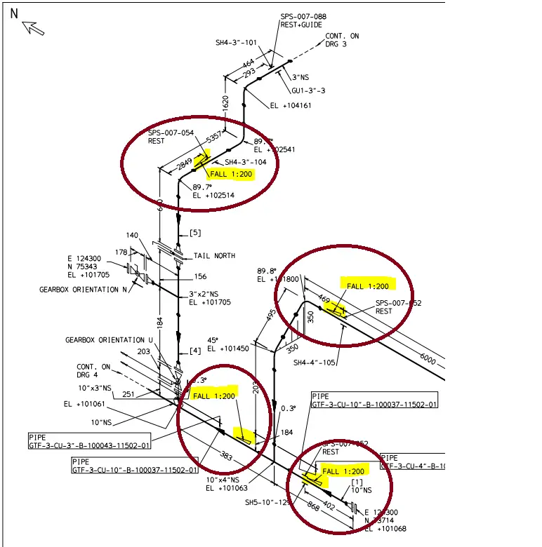
In the above piping isometric drawing, the piping slope is clearly mentioned. As can be seen, there is a fall of 1 mm for every 200 mm of pipe run. The value or magnitude of the piping slope is indicated as 1: 200, 1:100, 1:500, etc. All these terms signify that there will be an elevation change of 1 unit for each piping length of 200 units, 100 units, or 500 units respectively.
Note that, the piping slope can also be denoted as 1/100 or 1%. Both of these are the same as 1:100. All of these define the height deviation with respect to a certain length.
The slope in piping is symbolized using a right-angle triangle. The triangle will be placed adjacent to the line having a slope requirement. The elevation will increase towards the direction of the height (side) of the right-angle triangle. In a similar way, the elevation will drop towards the angle created by the base and hypotenuse. So, in the above image, as per the piping slope symbol specified, the elevation will decrease while moving from the south to the north direction. Similarly, for the pipe run traveling in the E-W direction (top ellipse in Fig. 1), the elevation will increase when moving from the West to the East direction.
Piping Slope in P&ID
Now refer to Fig. 2 below, which shows the part of a process P&ID.
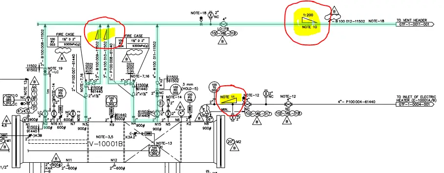
In the above figure, the slopes to be provided in piping are clearly indicated with a triangle symbol. The magnitude of the slope is written directly near the triangle or sometimes covered with notes as can be seen above. Notes 11 and 10 will explicitly mention the slope requirement. Also, the piping slope symbol mentions that there will be a drop in the elevation of the pipe towards the vent stack.
Piping Slope Calculation
As already mentioned, the required piping slope is usually mentioned in the P&ID (Refer to Fig. 2 above). So, once the slope value is known the change in elevation can easily be calculated. Let’s take the example of the E-W piping run in Fig. 1 which is highlighted towards the top end.
The total length of the element is 5357 mm and the slope towards the west direction is 1:200. So, we can use this information to mathematically calculate the change in elevation from one side to the other. So, the elevation difference of the line will be (1/200)*5357=26.785 mm. So calculating the piping slope is quite simple once these values are given. So, in Fig. 1, the Eastside edge will be at 26.785 mm higher elevation than the Westside edge. That we can check from the elevation values given in the isometric. Upon calculating the elevation differences given in the isometric we get 102541-102514=27 mm which is the same as what we calculated. In a similar fashion, we can easily calculate the piping slope for any other leg.
The value of the piping slope required is usually decided by the process engineers following industry experience and thumb rules. Some of the thumb rules that are prevalent in the industry are listed below:
- All piping in the main steam and hot and cold reheat line, turbine extraction system, condensate system, and turbine drains, of power plants are sloped down a minimum of ¹⁄₈ in/ft (10 mm/ m), in the direction of flow.
- It is common practice to design sanitary sewers with slopes sufficient to provide for velocities of 2 ft/s (0.6 m/s) when flowing full. Experience shows that with such slopes, trouble from deposits is seldom encountered.
Piping Slope Formula or Equation
The formula to calculate piping slope is given by the following equation:
Piping Slope=100*(Elevation or Height Change/Length of Pipe)
The above pipe slope formula calculates the slope in % terms. Both the height or elevation change and pipe length have to be in the same consistent unit. In general, in the FPS unit, the pipe length is provided in feet, and in the metric system, the length is given in meters.
Supporting Pipes having Slope
The usual practice for supporting pipes with slopes in process and power piping is to use a pipe shoe. In this type of piping shoe, the height of the shoe is variable from one side to the other corresponding to the pipe slope. A typical example is flare headers. They are supported with variable-height pipe shoes. Fig. 3 provides a typical shoe support that is used for supporting pipes having slopes.

Advantages of Pipe Slopes
The main requirement of slopes in piping is to avoid the accumulation of liquids inside the pipe. Other advantages are:
- When a piping slope is provided, the flow of the medium is easily maintained and gravity flow happens in the downward direction.
- The piping slope separates the flow of liquid along with the gaseous phase. For example, in the flare header the liquid is separated and returned back to KO Drum and the gas phase flows through the stack. This separation helps in avoiding slug flow problems.
Types of Piping Slopes
There are two types of piping slopes; positive slope and negative slope. When the pipe elevation drops in the direction of fluid flow it is known as a positive piping slope. On the other hand, if the pipe elevation increases in the direction of fluid flow it is known as negative piping slope.
Drain Pipe Slope
Based on the International Plumbing Code, the drainage piping system should be laid with a uniform slope. The amount of drainage piping slope depends on the pipe diameter. The usual minimum slope for drainage piping is as follows:
- For Pipe Size 2.5 inches and smaller: The minimum Slope requirement is 0.25 inches per foot
- For Pipe Sizes 3″ to 6″: The minimum Slope requirement is 0.125 inches per foot
- For Pipe Size 8 inches and larger: The minimum Slope requirement is 0.0625 inches per foot
Piping Slope Test
The Piping Slope Test or the Pipe Fall Test is the term majorly used in drainage piping systems. This is a process to ensure that the piping/pipeline system is installed with the correct slope or gradient. For systems requiring gravity flow, the piping slope test is crucial.
The Piping Slope Test procedure involves the following steps:
- Setting up a level: At one end of the pipe, a level is set up.
- Measuring the height: The height is then measured at the other end of the pipe.
- Calculating the slope: The pipe gradient or slope is then calculated by dividing the elevation difference by the pipe length and then multiplying the same with 100 to denote in % values.
Frequently Asked Questions
A 2% slope in piping means that the pipe has a vertical rise or fall of 2 units for every 100 units of horizontal length. To give an example, if a pipe has a length of 10 meters, then a 2% slope means that the pipe will rise or fall by 0.2 meters from one end to the other. A 2% slope is equivalent to a 1.15° angle.
The proper slope for a pipe depends on the type, application, and purpose of the pipe. Generally, pipes must slope downhill to drain correctly. The slope should be enough to allow the liquid to flow easily. In general, 1 in 100 is considered as a standard slope in oil and gas piping.
A 1% slope in piping informs that the pipe will vertically rise or fall by 1 unit for every 100 units of horizontal length. For example, if a pipe has a length of 10 meters, then a 1% piping slope means that the pipe will rise or fall by 0.1 meters from one end to the other. A 1% slope is equivalent to a 0.57° angle.
A 1 in 100 slope means that the pipe has a vertical rise or fall of 1 unit for every 100 units of horizontal length. It is another way of expressing a 1% slope.
A zero slope means that the pipe has no vertical rise or fall, and is perfectly horizontal. A zero-slope pipe does not drain by gravity and may require a pump or other device to move the fluid.
Slope is given in piping to facilitate the drainage of liquid or vapor from the pipe. Piping Slope also helps to prevent the formation of pockets or traps in the pipe, where liquid or vapor can accumulate and cause problems such as corrosion, erosion, pressure fluctuation, vibration, or blockage. Slope is especially important for pipes that carry two-phase flow, such as steam, condensate, or flare headers.