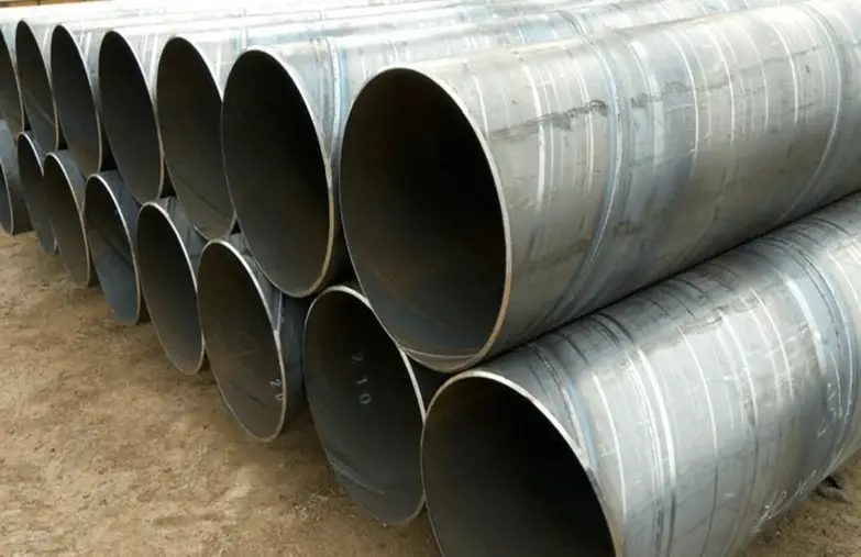
Hydrogen Induced Cracking (HIC) is a form of wet H2S cracking that is usually generated by high hydrogen concentration in metals. The mechanism involves atomic hydrogen which diffuses into a metal structure. The cracking due to HIC is formed parallel to the surface in the hoop stress direction. Hydrogen-induced cracking is more prevalent in sour service environments due to the presence of wet H2S. There are some other elements that may contribute to hydrogen-induced cracking. Some of these elements are arsenic, antimony, selenium, and cyanides. However, H2S is considered the most contributing element to hydrogen-induced cracking damage in the oil and gas industry. HIC causes blistering damage to many metals and alloys.
Hydrogen-induced cracking is more common in ferrous alloys due to its restricted slip capabilities in its BCC structure. HIC, in general, causes damage to steels with Rockwell C hardness of 22 or more at relatively low temperatures.
HIC can also occur during various elevated temperature processes like electroplating, pickling, phosphating, cathodic protection, arc welding, etc.
API Nelson curve provides a basis to understand the temperature zone over which the possibility of HIC increases. A typical curve indicating the HIC and Non-HIC zone is provided in Fig. 2 of the Sour Service article. Click here to refer to that article.
What is Hydrogen-Induced Cracking?
HIC = Hydrogen Induced Cracking = Caused due to Hydrogen attack on metal
Hydrogen-induced cracking is also known as
Hydrogen Damage
Hydrogen Embrittlement
Hydrogen Blistering
Delayed Cracking
Lamellar Tearing
Underbead Cracking
Stepwise Cracking
Hydrogen Induced Cracking Mechanism
In a wet H2S environment, the HIC mechanism starts with the formation of atomic hydrogen that diffuses throughout the metal or alloy that collects at voids or impurities within the metal structure. When these hydrogen atoms combine to form a hydrogen molecule, it produces high pressure within the cavity. The H2S forces these hydrogen atoms into the metal structure which in turn reduces the ductility and tensile strength of the metal. Slowly, this mechanism reduces the metal ductility such that stepwise internal cracks are formed which is known as hydrogen-induced cracking.
Refer to Fig. 1 which shows the mechanism of HIC.
Fig. 1: Mechanism of Hydrogen Induced Cracking (HIC)
Exhibit – Hydrogen-Induced Cracking
HIC is often visible on the metal surface as horseshoe-shaped. Regular inspection and testing need to be performed for eliminating the possibility of hydrogen-induced corrosion. The damages by HIC can be detected by Wet Fluorescent Magnetic Particle Inspection. For cracked components Phased Array Ultrasonic Testing is the most widely used and reliable non-destructive method.
Low alloy steels and high-strength titanium and nickel steels are more prone to hydrogen-induced cracking. Low-strength steels with tensile strength below 1000 MPa are usually not susceptible to HIC. Copper, Aluminum, and their alloys are the most resistant to HIC.
Fig. 2 shows an example of a crack by HIC.
Fig. 2: Example of Hydrogen Induced Cracking
Requirement of HIC Resistant Materials
Requirements for Carbon and Low Alloy Steels
The hardness of the Parent Material is Less Than 22HRC (237 BHN)
The steel shall be fully killed ( Silicon/Aluminum)
HIC test is performed following NACE TM0284. The unstressed HIC test specimen is exposed to the specified process environment saturated with hydrogen sulfide gas at 1 bar pressure for a duration of 96 hours (4 days) for the standard test. Fitness for purpose of testing is performed for durations of up to 30 days using reduced partial pressures of hydrogen sulfide.
Once the exposure period is finished, the test specimen is examined and any cracks developed are measured. The usual ratios that are used for hydrogen-induced cracking tests are the Crack Sensitivity Ratio, Crack Length Ratio, and Crack Thickness Ratio.
There is one more HIC test method known as Stress Oriented Hydrogen-induced cracking (SOHIC) test method. SOHIC test is performed following NACE MR0175 or ISO 15156 using the full ring test method as mentioned in BS 8701, tensile test method as mentioned in NACE TM0177-Method A, or four-point bend method as mentioned in NACE TM0316.
Thermal relief valves are also known as thermal safety valves, temperature relief valves, or thermal expansion relief valves. It is a safety device employed in liquid piping and pipeline systems to protect the equipment and system. When the thermal expansion of a liquid creates excessive pressure inside a closed system, the thermal relief valve pops up to release some fluid and bring down the pressure back to an acceptable limit. In general, when liquid heats up, it expands a little. When the temperature increase is quite high, the volume change of the liquid, though not by a large percentage, may increase the system pressure. To protect against this overpressure situation and to avoid explosion, thermal relief valves prove to be a good device.
What is a Thermal Relief Valve?
A thermal relief valve is a type of safety valve designed to release excess pressure from a system when it is subjected to temperature-induced expansion. When fluids or gases are heated, they expand, potentially leading to an increase in pressure that could exceed the system’s design limits. Thermal relief valves are engineered to mitigate this risk by allowing the excess pressure to escape, thus preventing potential damage or failure of the equipment. Fig. 1 below shows some typical thermal relief valves that are used in various industries.
Fig 1: Example of Thermal Relief Valves
Design Consideration for Thermal Relief Valves
The common size for thermal relief valves is relatively small. The usual size of thermal safety valves used for piping and pipeline systems are generally (1”x1”) or (¾”x1”) with a flanged end having a minimum orifice area of 0.110 in2.
Depending on the design code requirements a lifting device may or may not be required for thermal relief valves. In general, for air, hot water, or steam services with temperatures in excess of 600C lifting devices are normally specified.
Thermal relief valves are normally not vented directly to the environment. So, some sort of containment method is always suggested.
Thermal relief valves are usually designed based on API 526 or EN 14597 codes.
Applications of Thermal Relief Valves
Thermal safety valves are used for protection in case of excessive temperature for liquid applications in long pipes/pipelines exposed to the environment (sunlight), closed vessels, water heater applications, cooling water return side of heat exchangers between isolation valves, and pumps that recirculate water where heat buildup can be a problem. Piping in transport pipelines or storage areas, that will be regularly blocked during normal operation and can have a pressure rise due to solar heating or heat tracing calls for TRV installation.
The principal benefit of using a thermal relief valve in pump systems is that it allows an operator to run the unit in a bypass mode for an extended period, reducing the chances of premature seal wear on the high-pressure pump.
In general, thermal expansion relief valves are not intended for:
Process plant piping
Two-phase flow lines
Storage or transport piping sections that are not normally shut in for operational or emergency purposes
Systems that are not fully liquid filled, i.e. less than 95% liquid filled.
Thermal relief valves are employed in a variety of industries and applications. Some common areas where TRVs are used include:
Hydraulic Systems: In hydraulic systems, TRVs protect pumps, hoses, and other components from pressure spikes caused by thermal expansion. They ensure that the hydraulic fluid is maintained within safe pressure limits.
Compressed Air Systems: In air compressors and pneumatic systems, TRVs prevent pressure build-up due to temperature increases, safeguarding the compressor and associated equipment.
Boilers and Pressure Vessels: TRVs are crucial in boilers and pressure vessels to release excess pressure that may build up due to thermal expansion. This prevents catastrophic failures and ensures safe operation.
Chemical Processing: In chemical processing plants, where reactions can cause significant temperature and pressure changes, TRVs help maintain safe operating conditions by relieving excess pressure.
Working Principle of Thermal Relief Valves
TRV works mostly similarly to pressure relief valves. Even though the name is a thermal safety valve, the pressure increase is the main cause for its working. Under normal operation, the TRV remains closed by the spring force. When the force due to fluid expansion is great enough and exceeds the internal spring force, the valve pops up. Once the pressure reduces, the spring force again closes the thermal relief valve in a position to work smoothly.
Thermal safety valves work in an automatic manner and when the temperature falls below the set point it automatically reset.
Thermal relief valves are usually placed in a remote location without easy access. Also, normally temperature sensors, processors, or solenoid-type sensors are not used to control TRV systems. So, thermal expansion relief valves must be designed to be durable and work properly in case of system failure.
The basic mechanism of a TRV involves a spring-loaded valve that remains closed during normal operating conditions. When the system experiences a temperature-induced pressure rise, the valve opens to release excess pressure, thus protecting the system from damage.
Thermal Expansion: As temperatures increase, the fluid or gas inside a closed system expands. This expansion raises the internal pressure.
Pressure Threshold: The TRV is set to open at a specific pressure threshold. This threshold is usually predetermined based on the system’s maximum allowable working pressure.
Valve Actuation: Once the internal pressure exceeds the threshold, the TRV opens, allowing the excess fluid or gas to escape. This reduces the pressure back to a safer level.
Valve Closure: After the pressure decreases to a safe level, the TRV closes, and the system resumes normal operation.
Types of Thermal Relief Valves
There are three main types of thermal relief valves as mentioned below:
Spring-Loaded Thermal Relief Valves
Pilot-Operated Thermal Relief Valves
Balanced Bellows Thermal Relief Valves
1. Spring-Loaded Thermal Relief Valves
Description:
Mechanism: Utilizes a spring to keep the valve closed until the pressure exceeds a set point. When the pressure rises due to thermal expansion, it overcomes the spring force, causing the valve to open and release excess pressure.
Operation: The spring is calibrated to the pressure at which the valve should open. When the pressure increases beyond this point, the valve opens to relieve the excess pressure.
Advantages:
Simplicity: Straightforward design and operation.
Cost-Effective: Generally less expensive compared to more complex valve types.
Applications:
Commonly used in hydraulic systems, compressed air systems, and other systems where thermal expansion is a primary concern.
2. Pilot-Operated Thermal Relief Valves
Description:
Mechanism: Features a pilot valve that controls the main relief valve. The pilot valve responds to pressure changes and opens or closes the main valve accordingly.
Operation: The pilot valve operates at a lower pressure and controls the main valve to open at a higher pressure set point, providing precise control over the pressure relief process.
Advantages:
Precision: Offers more precise control of pressure relief.
High-Pressure Applications: Suitable for systems requiring accurate pressure control and handling higher pressures.
Applications:
Used in applications with high-pressure conditions or where precise pressure control is essential, such as in large-scale industrial systems.
3. Balanced Bellows Thermal Relief Valves
Description:
Mechanism: Includes a bellows element that helps to balance the pressure on both sides of the valve seat, reducing the effects of varying pressures and temperatures on the valve operation.
Operation: The bellows maintain a constant force on the valve seat, allowing it to open and close smoothly despite fluctuations in system pressure.
Advantages:
Stability: Provides stable operation under varying pressure and temperature conditions.
Reduced Sensitivity: Less affected by changes in the system’s pressure and temperature.
Applications:
Used in applications where pressure and temperature fluctuations are significant, such as in chemical processing or high-temperature systems.
Thermal Relief Valve Symbols
In P&IDs, the thermal relief valve symbol is provided as per Fig. 2 shown below:
Fig. 2: Symbol for Thermal Relief Valve (TRV)
The Importance of Thermal Relief Valves
Thermal relief valves (TRVs) are crucial components in various fluid and gas systems, serving essential roles in protecting equipment, ensuring safety, and optimizing performance. Here’s a detailed look at why thermal relief valves are important, using the key data provided:
1. Protection Against Catastrophic Failure
Thermal relief valves are crucial for protecting the integrity of systems from overpressure caused by temperature changes.
Prevention of Catastrophic Failures: When a system experiences a rise in temperature, the expansion of fluids or gases can lead to a significant increase in pressure. Without a TRV, this overpressure could exceed the design limits of the system, potentially resulting in catastrophic failures such as ruptures or explosions. By opening at a predetermined pressure, TRVs release the excess pressure, thus preventing such severe outcomes.
Cost Avoidance: Catastrophic failures often result in costly repairs or complete replacements of damaged equipment. By maintaining pressure within safe limits, thermal relief valves help avoid these significant financial burdens.
Safety Hazards Prevention: Overpressure situations can pose serious safety hazards to personnel working with or near the affected systems. By preventing overpressure, TRVs contribute to a safer working environment and help avoid injuries or fatalities.
2. Regulatory Compliance
Thermal relief valves are often required by industry standards and regulations, ensuring safety and legal compliance.
Adherence to Standards: Organizations such as the American Society of Mechanical Engineers (ASME) and the Occupational Safety and Health Administration (OSHA) mandate the use of thermal relief valves in specific applications. Compliance with these standards is not only crucial for legal reasons but also for ensuring the safety of personnel and the protection of the environment.
Avoidance of Legal Liabilities: Failing to comply with regulatory requirements can result in legal liabilities, fines, or penalties. By installing and maintaining TRVs as required, organizations can avoid such legal issues and ensure that their systems meet safety and operational standards.
3. System Performance and Efficiency
Thermal relief valves contribute to the optimization of system performance and operational efficiency.
Energy Waste Reduction: By releasing excess pressure, TRVs help prevent energy waste associated with overpressure conditions. This contributes to a more efficient operation of the system, as it avoids unnecessary strain and energy loss.
Reduced Wear and Tear: Excessive pressure can accelerate wear and tear on system components, leading to more frequent maintenance and shorter equipment life. TRVs help mitigate this issue by controlling pressure levels, thus extending the life of the components and reducing maintenance needs.
Improved Overall Performance: Maintaining optimal pressure levels helps ensure that the system operates efficiently and effectively. This can lead to enhanced overall system performance and reliability.
Difference between TRV and PRV
Even though the working mechanisms of both thermal relief valves (TRV) and Pressure relief valves (PRV) are almost similar, they have some differences.
A TRV is usually small, whereas a PRV can be of big sizes.
TRV acts when overpressure occurs because of temperature increases and relieves a small quantity of fluid, whereas PRV is sized to protect from any kind of overpressure and usually releases large quantities of fluid.
Safety is the main purpose of both TRV and PRV.
Thermal relief valves are vital components in various fluid systems, providing essential protection against pressure buildups caused by thermal expansion. Understanding their function, types, applications, and maintenance is crucial for anyone involved in the design, operation, or maintenance of hydraulic systems, compressors, or pressure vessels.
What is an Air Relief Valve, Air Release Valve, or Air Valve?
Air Relief Valves are popularly known as Air Release Valves or Air Valves. Air Relief Valves work as a safety device by releasing the air pockets that may be generated at each high point of a fully pressured pipeline. If not released, this trapped air may cause various problems like flow issues, pump failures, corrosion, faulty instrumentation readings, and pressure surges. Also, air trapped in the pipeline system calls for additional energy consumption. So, air relief valves function as a very important element in such situations.
Air can enter into a pipeline from the following sources:
The pipeline itself – Before commissioning and start-up of any pipeline, it is filled with air. When fluid enters the pipe, it displaces the air and takes its position. The air must be completely removed during this stage otherwise it will accumulate at the highest points.
Water usually contains 2% air by volume. Adhesives or other thick fluids normally trap air in pockets. So, when the fluid flows through the system, sometimes air separates out from the mixture/pockets and accumulates at system high points.
Several pieces of equipment like pumps, packing, valves, and pipe joints can also suck air which then can accumulate at the high points.
This accumulated air creates flow restriction which increases the pressure head loss. This increases pumping cycles, which translates into higher energy consumption.
At the same time, while flowing through the restricted pipe, its velocity increases. With the increase in velocity, it may be possible that part or all of the air pocket will break away and be carried downstream. This increases the possibility of a water hammer which is known to cause serious damage to pumps, valves, and pipes. It is, therefore, air accumulation in system high points must be avoided.
Again, when the fluid velocity is not sufficient enough to carry away the air pockets, they continue to grow. Larger air pockets make the system completely air bound and create flow stoppage.
Air release valves or air relief valves work continuously to eliminate excess air from the system which in turn results in a smooth and efficient operation.
Air release valves open against internal pressure and release the system’s accumulated air. Air Release Valves are widely used for increasing pipeline efficiency and water hammer protection.
Fig. 1: Typical Air Release Valves in a Pipeline
Working of Air Release Valves
Automatic air release valves are located at the highest points of the pipeline or other systems where air naturally collects. The air bubbles enter the air relief valve and displace the inside liquid. Thus the liquid level is lowered. When the liquid level drops to such an extent that it no longer buoys the float, the float drops causing the valve to open which vents the accumulated air into the atmosphere.
Once the air is released, the liquid re-enters the valve, lifting the float until the seat presses against the orifice, and closing the valve. This cycle continues automatically and maintains an air-free system.
Components of an Air Release Valve
An air release valve or air valve consists of the following components:
Main Body: Compact metal body that houses the inner floats and upper mechanism.
Inner Float Assemblies that consist of a large orifice float, small orifice float, upper float, upper seat, mesh outlet, and cover.
Proper Installation of Air Relief Valves
Air release valves must be installed at high points where the air is likely to be collected in the piping or pipeline system. It is preferable to install the device in the vertical position with the inlet down. If servicing is required, a shut-off valve must be added below the air relief valve. In general air relief valves or air valves are installed in the following locations:
Air relief valves are popular for water pipelines and sewer force mains. However, they are ideal for any type of closed-loop or pressurized piping or pipeline system that has the chance of entrapping air.
Compared with other types of air valves, air release valves have small orifices. So, the best application for air relief valves is the applications with smaller volumes of air to exhaust.
Advantages of Air Relief Valves
Air release valves provide the following benefits:
They protect the pipeline and piping system.
They maintain the system’s efficiency by reducing pressure loss.
They are automatic.
They continuously vent entrapped air from high points.
They are also used to allow air back into the pipeline during emptying the liquid.
Disadvantages of Air Relief valves
Air release valves are usually not suitable for quick filling or emptying of pipelines. In such situations, air relief valves must be accurately sized for the specific application.
So, overall air release valves safeguard the pipeline and pumping system from damage. They lower energy consumption increase efficiency, and eliminate surge potential and hence, must be installed in every system having the possibility of air accumulation.
What is Pipe Spacing? Pipe and Pipeline Spacing Chart
Pipe spacing refers to the specific distance maintained between adjacent pipes in a piping system. Proper spacing ensures that pipes do not interfere with each other during thermal expansion, maintenance, or operational movements. It also helps in avoiding mechanical damage and provides sufficient room for inspection and repairs.
Why is Pipe Spacing Important?
Maintenance and Accessibility: Adequate spacing allows for easier access to pipes for routine maintenance, repairs, and inspections.
Thermal Expansion: Pipes expand and contract with temperature changes. Proper spacing accommodates these movements to prevent clashing and potential damage.
Safety: Sufficient spacing helps avoid mechanical interference and reduces the risk of leaks or system failures.
Optimized Layout: Efficient spacing can minimize the footprint of pipe racks, reducing construction costs and saving space.
Factors Influencing Pipe Spacing
Several factors must be considered when determining the appropriate spacing between pipes:
Pipe Diameter, Flange Rating, and Size: Larger pipes and flanges require more space. The diameter of the pipes and the size of their flanges (if applicable) significantly influence the spacing.
Insulation Thickness: If pipes are insulated, the thickness of the insulation must be considered when calculating spacing.
Thermal Movement: Pipes experiencing significant thermal expansion or contraction require additional spacing to accommodate these movements.
Pipe Racks and Supports: In pipe racks, spacing must account for the arrangement of flanges and the type of supports used.
What is a Pipe Spacing Chart?
A Pipe Spacing Chart provides the minimum distance between two adjacent pipes or pipelines. Whenever two pipes run parallel to each other, piping designers or engineers must maintain a minimum gap between the two pipes or pipelines.
Placing the pipes in proper order following a pipe spacing chart provides various benefits like:
Proper pipeline spacing prevents the clash between pipes/pipelines during construction and erection.
Sufficient Spacing accommodates sideways thermal movement of pipes generated due to thermal or occasional movements.
So, to fulfill the above requirements and help pipeline and piping engineers during their pipe-laying activities, organizations prepare a standard pipe spacing chart. Following those standardized pipe spacing charts, the activities become quicker, and the chances of error during pipe and pipeline placement are reduced a lot. So, in a sentence, we can define a pipe spacing chart as a tabular representation of minimum pipe-to-pipe distances of various sizes.
Pipe spacing charts are very useful while routing pipes over a pipe rack or sleepers where lines of various sizes run parallel to each other.
Pipe Spacing Criteria
Various factors need to be taken one while piping or pipeline spacing. Some of those factors are:
Adequate space for maintenance, inspection, and component repair must be provided during the layout.
Spacing should be considered the worst free thermal movement between pipes. When the thermal movement is large, additional pipe spacing must be considered so that pipe thermal displacement is accommodated.
The usual practice to develop a pipe spacing chart is to consider a 25 mm gap between the outermost periphery of the piping components. So for example, if there are two pipes running parallel to each other, one having insulation and the other having a flange connection, a minimum of 25 mm gas has to be maintained in between the Insulation surface and flange surface. If both lines have a flanged connection, the flanges must be staggered to reduce pipe spacing between the two.
The formula for pipeline spacing:
The basic formula that is generally used to develop a pipe spacing chart is:
Centre to center distance between two adjacent pipes (mm)=half outer diameters of the bigger size pipe flange (OD/2)+half outside diameter of smaller size pipe (od/2)+ insulation thickness of both the smaller and bigger size pipe as applicable (T+t)+ 25 mm +Thermal displacement=(OD+id)/2 + (T+t) + 25 +Thermal displacement
The Pipe Flange Outer diameter is available in the flange standard. For example, ASME B16.5 is used for flanges up to 24″ in size and ASME B16.47 is used for flanges of size 24″ to 60″. AWWA C207 is used for flanges above 60 inches in size. For custom flanges or flanges designed with other standards, you have to refer to that standard.
Pipe outside diameter you will get in ASME B36.10/B36.19 standard.
Pipe insulation thicknesses, you will get in the project-specific insulation specifications. That will be a project-specific in-house document and can vary from project to project depending on the design criteria.
Thermal displacement needs to be calculated based on the worst situation consideration. For example, if two lines are running parallel to each other. One has a design temperature of 2500C (hotline) and the other has a design temperature of -460C (cold line). So, the hot line will expand and the cold line will compress. So, while calculating the pipe span both this displacement needs to be added. This means if the hot line expands by 30 mm and the cold line compresses by 15 mm then the thermal displacement that needs to be added in the pipe spacing calculation is 30+15=45 mm. However, if both lines are hot lines, then while thermal displacement calculation, consider a situation when one pipe is operating and the other is in ambient condition (preferably consider winter’s lowest ambient temperature).
So, using the above parameters in the above equation, you can easily calculate the pipe-to-pipe distance requirement for pipes of any size.
Fig. 1: Pipe Spacing Explanation
Pipe Spacing Chart
Standard pipe spacing charts are developed by organizations that provide center-to-center distance between two pipes. If there is a considerable amount of lateral thermal displacement (usually >15 mm) then the same needs to be added with the spacing values given in the standard pipe spacing charts. Typical pipe spacing charts are provided below to get an idea of the pipeline spacing charts used in the piping industry. However, these values may vary depending on the component design codes. So, it is always better to practice calculating using the above formula.
Pipe Spacing chart for pipes with 150 rating flanges
Fig. 2: Pipe Spacing chart for pipes with 150-rating flanges
Pipe Spacing chart for pipes with 300-rating flanges
Fig. 3: Pipe Spacing chart for pipes with 300-rating flanges
Pipe Spacing chart for pipes with 600 rating flanges
Fig. 4: Pipe Spacing chart for pipes with 600-rating flanges
Pipe Spacing chart for pipes with 900 rating flanges
Fig. 5: Pipe Spacing chart for pipes with 900-rating flanges
Using a Pipe Spacing Calculator
A pipe spacing calculator is a valuable tool for determining the correct spacing between pipes based on various criteria. Here’s how to use it:
Select the Configuration: Choose from the four provided options, such as spacing between pipe centers, flange centers, or bare pipes.
Input Dimensions: Enter the outer diameter (OD) of the pipes and flanges. For configurations involving flanged components, include the OD of the flanges.
Calculate Spacing: The calculator will provide the minimum spacing required between pipes based on your input.
Spacing Between Pipes on a Pipe Rack
When pipes are arranged on a pipe rack, specific considerations are required:
Staggered Flanges: If adjacent lines have flanged components, staggered arrangement is often necessary to optimize space and reduce the required footprint.
Clamped Supports: If using clamped supports, larger spacing may be required. For cost-effectiveness, clamped pipe supports at a 45-degree angle are recommended.
Special Considerations
Protruding Valves: For valves like full-bore ball valves with higher flange ratings, the valve body may extend beyond the flange OD. In such cases, specific calculations are needed to ensure adequate spacing.
Non-Staggered Components: If flanged components cannot be staggered, ensure that the spacing accounts for the largest flange OD and any additional clearances.
Drying is a process where moisture is removed from a wet material or a gas to make it dry. This technique is often used in different industrial operations like sugar production, milk powder production, soap bar production, etc. The energy for drying is supplied by external means like hot gas or air.
Vacuum drying is a process where heat-sensitive material is dried by reducing its pressure as we know by reducing pressure moisture can be removed easily at relatively lower temperatures. Because character tics of heat-sensitive materials can be degraded on exposure to hot air or gas.
Drying Mechanism
Drying is dependent on the principles of mass & heat transfer. Moisture vaporizes at the solid surface while the solid is heated to a sufficient temperature. The heat required (Sensible heat & heat of vaporization) for drying is usually supplied by hot air or gas. After the vaporization of surface moisture, more moisture is transported from inside the solid to its surface. The different types of mechanisms may be classified into
Liquid diffusion
Pressure-induced transport
Vapor diffusion
Capillary force
Different Types of Moistures
Moisture content: It is the quantity of moisture in wet material. It is generally expressed in mass ratio units (kg moisture/kg of dry solid).
Bound Moisture: The amount of moisture in a solid that causes a vapor pressure less than the normal vapor pressure of water at the given temperature is called bound moisture.
Unbound Moisture: The amount of moisture in a wet solid in excess of the bound moisture is called unbound moisture.
Equilibrium moisture: It is the moisture content in a solid that is in equilibrium with the drying medium of a given temperature & relative humidity.
Free moisture: It is the moisture content in a solid in excess of the equilibrium moisture. Only free moisture can be removed by drying under a given set of conditions.
The Drying Rate Curve
The time taken by drying operation of a moist solid to final moisture content can be determined from the rate of drying under certain conditions. The drying rate is a function of the temperature, humidity, flow, and transport properties of drying gas. The drying rate (N) is determined by the experiment method. Refer to the equation given in Fig. 1 below
Fig. 1: Equation for Drying rate
Types of Dryers
There are several types of dryers available to suit specific needs as a wide variety of wet solids, slurries, and solutions are required to be dried on an industrial scale. The performance of a dryer depends on how good the contact between the wet solid and the drying gas is.
Fig. 2: Classification of Dryers
Tray Dryer
A tray dryer is the most common type of dryer generally used in industries where cross-circulation drying occurs. The moist solid is taken in a number of trays; the trays are stacked in the drying chamber providing a gap so that drying gas may be passed over the exposed top surface of the solid spread on a tray. The drying gas (usually air) is heated in contact with steam coils. A blower fitted inside the cabinet forces the hot air over the trays. A portion of the air is circulated inside the cabinet and the rest leaves the chamber carrying evaporated moisture. The temperature, humidity, and velocity of air may be regulated by adjusting the gas flow rate.
Advantages of Tray Dryer:
-Each batch is dried & handled separately
– It’s more feasible in consumption of fuel
-Easy to clean, accessible, and control
-Less space requirement
-It’s operated batch-wise
-It provided a tendency to over-dry the lower trays.
-It requires small labor costs for loading & unloading trays.
Rotary Dryer
Rotary dryers are often called the ‘workhorse of chemical dryers’ and fall in the most widely used class of continuous dryers in process industries. It consists of a slowly rotating slightly inclined cylindrical shell fed with moist solid at the upper end. The material inside a rotary dryer flows along with the rotating shell, gets dried, and leaves the dryer at the lower end. The heat for drying is provided by a hot flue flowing outside and heat is transferred through the shell.
Countercurrent flow in a rotary dryer ensures a more uniform distribution of the temperature-driving force along with the shell.
What is a rotary dryer used for?
This type of dryer is suitable for relatively free-flowing, non-sticky, and granular materials e.g. almost all types of crystals after crystallization and washing such as table salt, sodium sulfate, ammonium sulfate, minerals, and organic salts. Also, it is used for dehydrating waste materials, and animal feedstuffs.
Fig. 3: A Typical Rotary Dryer
Vacuum Dryer
The vacuum dryer is provided with a heating jacket and slow-moving agitator for wet material. A moderate vacuum usually not below 10 mm Hg is used. The vapor drawn by the vacuum device may be condensed if recovery is desired. The conical shape allows faster discharge of the dry product through the bottom. This type of dryer is used for drying powders, dyes, chemicals & pharmaceuticals.
Fig. 4: Typical Vacuum Dryer
How does a vacuum dryer work?
It is a batch operation where the pressure and humidity are reduced by means of vacuum pumps in an air-tight vessel. Thus, by lowering the atmospheric pressure in the chamber the materials inside the vessel dry more rapidly through contact with heated walls indirectly.
Advantages of Vacuum drying:
Vacuum drying is a process, where heat-sensitive, toxic powders and hygroscopic & granules have been dried by avoiding exposure of excess heat as well as certain nutrients, which can break down on exposure to excess heat. Taste, appearance, and other properties may degrade under too much heat.
Vacuum drying employs a safe & highly effective technique for drying large volumes of heat-sensitive granules or powders. The temperature is usually very low compared to what will be required in a common industrial dryer.
Fluidized-bed Dryer
This type of dryer is used for drying free-flowing moist solids. The working principle is very simple. The moist solid is fed continuously into the dryer by a screw feeder and is kept fluidized by a stream of hot drying gas. The dry product is also continuously removed through a nozzle at an appropriate location. The fines carried over by the gas are separated in a cyclone separator or bag filter. A fluid-bed dryer is widely used to dry a variety of materials such as minerals, pharmaceuticals, seeds, cereals, spices, fish meals, waste materials, etc.
Fig. 5: Typical Fluidized bed dryer
Spray Dryers
A spray dryer is installed to dry the atomized droplets contained in the feed that may be a solution or slurry of fine particles. It consists of a big drying chamber which may be 15m in diameter and 35 m tall.
How does a spray dryer work?
The feed is fed through an atomizer located at the top. The hot gas is introduced either at the top or at the bottom (concurrently or counter currently). The hot gas temperature may be as high as 700ᵒC but normally is kept within 250-280ᵒC. Drying of the droplets dispersed in the hot gas occurs in a very short contact time of a few seconds. The process of atomization of the feed is performed by a rotating disk and a high-pressure nozzle. The liquid or slurry is fed onto the disk at the center which is centrifugally accelerated and then ejected from the periphery of the disk at a speed of 80-200 m/s. The angular velocity of the disk is 3000-20000 rpm.
Advantages of Spray dryer:
The spray dryer can atomize handle abrasive slurry or paste using a whirling disk without erosion.
It is also considerably flexible with respect to feeding rate and properties.
The size of the atomized droplet is 10-20 microns
Due to its conical bottom shape small dried particle is removed through a product conveying line.
Because of the very short contact time between droplets and the drying gas. A spray dryer is suitable for drying heat-sensitive materials.
A spray dryer is also used to dry a variety of other liquids, e.g. milk, egg, coffee, tea, tannin some polymeric resins, pharmaceuticals, organic and inorganic activated pharmaceuticals ingredients, detergents, etc.
Fig. 6: Spray Dryer
Selection of Industrial Dryers
The following data need to be collected before the selection of dryers.
The physical form of feed – Liquid, slurry, pasty, free-flowing powders, granular, crystalline, continuous sheet, discontinuous sheet.
Dryer throughput (Kg/hr).
Upstream/Downstream equipment – batch or continuous.
For particulate feed products, mean particle size and size distribution.
Inlet/outlet moisture content of the product.
Maximum allowable product temperature.
Drying curve.
Feed cohesiveness.
Product fragility.
Contamination by drying gas.
Explosion characteristics (vapor/air and dust/air).
Toxicological properties.
Corrosion aspects.
Product value.
Experience already gained.
A typical decision tree diagram is provided in Fig. 7 and Fig. 8 below for the selection of batch dryers and continuous dryers.
Fig. 7: Decision Tree for batch dryer selection.
Fig. 8: Decision Tree for continuous dryer selection
Proper dryer selection is a challenging issue and has a significant impact on the economic growth of a plant, it is not at all recommended to fully depend on the vendors’ information & recommendation but users should come up with preliminary criteria for dryer selection prior to contacting any vendor. The above decision trees for the selecting batch and continuous dryers can be used during the initial assortment of a large number of dryers.
Plate Tower vs Packed Tower: Selection, Differences, Advantages, and Disadvantages
Distillation is a process in which a liquid or vapor mixture of two or more substances is separated into its component parts of desired purity through heat and mass transfer. The degree of separation in the distillation process depends on the relative volatility of the components to be separated. In the process of distillation, the vapor phase contains more volatile components (that have lower boiling points), this vapor is cooled and condensed at the overhead condenser and it consists of containing more volatile components. On the other hand, the original mixture will contain more of the less volatile (that have a higher boiling point) component.
There are different types of distillation columns (also known as distillation towers) that are designed to perform specific types of separation. Two main types of columns are plate columns and packed columns. There are differences between these two types of columns. In this article, we will be providing the difference between plate column and tray columns, their selection, their applications, advantages, and disadvantages.
What are the differences between the Packed Column and the Plate Column?
The main differences between packed and plate towers are given in the table below:
Packed Columnsor Packed Tower
Plate Column or Tray Tower
Packed columns are generally used in a smaller diameter (less than 600 mm)
Plate column is used for relatively large diameters & a large number of stages.
A packed column is suitable for low-capacity operation.
Plate columns can handle a wider range of gas and liquid flow rates.
Handling corrosive liquid-packed columns is more economical as cheap ceramic packing material or chemical-resistant packing elements which is available can be easily used.
Handling corrosive liquid-packed columns is less economical.
It is appropriate for accommodating the handling of foaming liquid.
It is not appropriate for handling foaming liquid.
For packed column maintenance work or cleaning cannot be performed easily. It consumes time and manpower.
It is much more accessible for the maintenance of plate columns by installing maintenance holes on the plates to maintain fouling.
For vacuum service, a packed column is more feasible as the pressure drop per stage is smaller.
For vacuum service plate column is not economical as it causes high-pressure drop.
For side stream applications, a packed column is not suitable.
For side stream application plate column is best suited.
Packed columns are differential contractors where transfer of mass happens across the length of the contactors & equilibrium is not reached at any point between the phases.
In plate columns, equilibrium is reached between stages where the mass transfer occurs intermittently.
In-packed column packing is used as a gas-liquid contacting device.
In a plate column, the plate is used as a gas-liquid-containing device.
The design of a packed tower basically involves the height of the transfer unit (HETP) calculation for a given separation.
For designing plate columns, the number of theoretical stages is to be calculated to effect a given separation.
Packed towers are simple to construct.
Plate columns are complex in construction.
Different types of packings are used for gas-liquid contacting like Raschig rings, Pall rings, Berl saddles, Intalox saddles, etc.
As a gas-liquid contactor, different types of trays are used like sieve trays, bubble cap trays, and valve trays.
Table 1: Plate tower vs Packed tower
Advantages & Disadvantages of a Packed Column:
There are several advantages of a packed column as well as disadvantages too.
Advantages of Packed Tower
The main points of advantages have been captured here,
It requires minimum structure.
The packed column causes a minimum pressure drop.
The liquid hold-up is relatively low in the packed column.
The packed column can easily handle highly corrosive, foaming fluid.
It requires low investment.
Disadvantages of Packed Tower
The disadvantages are as follows,
The packed tower is relatively inflexible for handling a wide range of G/L ratios.
So that it cannot easily handle wide ranges of either vapor or liquid rates per unit cross-section.
In packing, gas-liquid mal-distribution can happen.
It cannot handle dirty fluids that tend to deposit.
Due to uneven distribution channeling happens frequently in the packed column which results in poor mass transfer.
A packed column is suitable for that service where large temperature changes happen.
Advantages & Disadvantages of Plate Column
Advantages of Plate Column
The main points of advantages have been captured here,
The plate column provides stage-wise contact so that equilibrium can be reached.
It can operate on a wider range of gas/liquid ratios.
Cleaning & maintenance can be done easily for plate columns.
The packed column causes a minimum pressure drop.
Side-stream can be easily drawn from the plate tower.
Plate columns can be scaled up to a large diameter.
Hydraulic & mass transfer behavior can be predicted.
Disadvantages of Plate Column
The disadvantages are as follows,
Plate columns cannot perform properly for foaming service as it reduces the performance and efficiency of the plat columns.
The liquid hold-up is relatively high for the plate column.
It is not economical at all for corrosive service. If it is bound to use then corrosion resistant plate can be used whose cost is too high to use.
The plate column requires huge support to install which increases cost.
How to select a Packed Column and a Plate Column?
The selection of a particular type of equipment for a gas-liquid application depends upon several factors like capacity, efficiency, pressure drop, fluid properties, hold-up, budget, etc. But the basic selection criteria are cost and profit but in some cases, the choice is made on the basis of quantitative analysis of the relative advantages and disadvantages of packed tower and plate tower. Some of the merits and demerits that are generally considered are,
Plate towers can operate over a broader range of gas-liquid flow rates without flooding.
Plate tower provides better separation by repeated mixing and separation while packed tower can lead to back mixing and channeling.
Because of the mal-distribution of gas-liquid arising in the packed tower, the plate tower is more reliable.
For solid-dispersed liquid plates, the tower is more suitable as maintenance and cleaning can be done easily in a plate tower.
Design information on the plate towers is more readily available.
For an exothermic mixture, intermediate cooling can be required which can easily be provided to remove excess heat by providing a cooling arrangement.
Pump around pump can be easily used in the plate-type column.
For foaming liquid packed tower is usually preferred.
As the pressure drop in a packed tower is relatively low so for vacuum service it can be easily used.
Hold-up liquid is low in the packed tower so they are used for heat-sensitive material where they can deteriorate under exposure to high temperature
Column Internals
Column internals is the components of the column that provided a contact area for gas-liquid separation.
For the Tray column, the internals are,
Sieve Tray
Valve Tray
Bubble-cap Tray
Others (Like Max-Frac trays)
Packed column internals are packings which are two types which are Random packing and structured packing. Random packing or stacked packing has different types of packing rings that are,
Raschig rings
Pall rings
Berl saddle
Intalox saddle
For structured packing, there are packing rings that are proprietary items of vendors like Mellapak, Flexi Grid, Sulzar type, etc.
Bubble Cap Tray:
Bubble cap tray distributes them as phase into the liquid phase like fine bubbles or droplets. It prevents weeping that is drainage through the gas passage at low gas flow rates. A bubble cap tray is not used normally as it causes high-pressure drops and higher costs.
Fig. 1: Bubble cap, Sieve, and Valve Tray
Sieve Tray:
This type of tray consists of a perforated plate which is having holes through which gas can be dispersed into the liquid on the plate. It is basically a metal sheet and it has hundreds of perforations of sizes of 3-12 mm. The area that the holes consist of is almost 5-15% of the tray area. These trays are commonly used nowadays as it is very simple in construction, as well as their cost is low.
Valve Tray:
A valve tray is nothing but a perforated metal sheet where the holes are covered with movable caps or discs. The diameter of the discs is up to 38 mm and held in the plate by legs that prevent upward motion of the discs for gas flows.
Raschig Ring:
This type of packing is the tubular type generally used in the fractional distillation columns. They are basically cylindrical tube and their length and diameter are almost equal. It can be made of carbon steel, ceramic, and plastics.
Fig. 2: Raschig Ring, Pall Ring, and Berl Saddle
Pall Ring:
This type of ring is made of SS04, SS316L metal alloy. Besides this, it can be made of Carbon steel and specialty alloys such as Monel 400 and Hastelloy, C276. Various sizes of pall rings are available such as 16 mm, 25 mm, 38 mm, and 50 mm.
Berl Saddle:
This type of ring causes low-pressure drop and high efficiency. It provides a large effective interfacial area along with high mechanical strength. The cost of this packing material is not high as it contains fewer metal parts. It is available in various sizes that give different combinations of efficiency and pressure drop.
What is Random Packing?
Random packing used in separation columns like distillation column increases surface area for mass transfer between vapor/liquid so that separation becomes easier. The small pieces of random packing material in a distillation column are made to provide a large surface area. Random packing provides a maximum surface-to-volume ratio and lowers the pressure drop. The degree of efficiency of random packing depends upon several factors like pressure drop and capacity, porosity, etc. Typically, when random packing is large in size, capacity is increased at the cost of lower efficiency. On the other hand, when random packing is smaller in size, efficiency increases at the cost of lower capacity. Examples of random packing are Raschig rings, Pall rings, etc.
Fig. 3: Random vs Structured Packing
What is Structured Packing?
Structured packing gives uniform distribution of packing materials which is usually large in size. It is usually made of thin corrugated metal sheets which force the fluid into specific, preordained arrangements within the tower. This type of packing is usually used in offshore applications. It spreads the liquid into a thin film. This configuration causes more contact & increases the degree of separation. Structured packing usually leads to low-pressure drop so it can handle larger volumetric flow than random packing. For natural gas dehydration, styrene manufacturing structured packing is used.