Pipe routing is an engineering technique applied for selecting a proper piping layout fulfilling code and standard requirements, economic considerations, and most importantly safety. It is the responsibility of piping designers and piping design or piping layout engineers to design the most economic and safe piping route considering all the engineering requirements.
Pipe routing is one of the most complex activities and the core of piping engineering for oil & gas, chemical, and power piping plants. While pipe routing the piping engineer has to comply with various engineering requirements like process requirements, accessibility, safety, constructability, maintenance, and operational requirements. To comply with all such engineering requirements and develop a techno-economical, safe, and cost-effective pipe routing the piping professional must be able to manage the following four major piping components:
To develop an economic and safe pipe routing, the responsible piping design engineer should possess the following skills:
Input Reading and Interpreting Skills: The piping design engineer must be competent in reading and understanding P&IDs, Piping Material Specifications, Project Specifications, Engineering guidelines, Code and Standard requirements, Equipment GA drawings, and any other design requirements.
3D and 2D software skills: the piping designer must be efficient to handle the 2D and 3D software.
Piping Skills: The concerned engineer or designer must be conversant with pipes and fittings, instrument items, valves, other inline items, piping supports, Piping Support Spans, and other piping accessories to build a good piping design.
Pipe Routing Concepts
Pipe routing is not a single activity. While doing pipe routing, the engineer must do the support placement and support selection. Without support placement or without deciding the pipe support locations if a pipe layout is decided there is no meaning of that pipe routing. The piping designer must decide on the first support location and then based on the pipe support span decide on the other support locations. If there is a group of lines running together over the same structures then usually the smallest large bore pipe is decided as the basis for support locations.
The usual parameters that must be considered for finalizing the pipe routing of the industrial piping to make it techno-economic and safe are
Simple and Straight routing as much as possible.
Grouping lines together to reduce the number of structures required for pipe support.
Stress Corrosion Cracking or SCC is a slow failure mechanism of engineering materials in a corrosive environment. Many ductile metals and alloys fail each year due to stress corrosion cracking which starts with a crack initiation, propagation, and growth of that crack to a damaging limit in exposure to a corrosive environment. Stress corrosion cracking is alloy and environment-specific which means the mechanism varies widely depending on the material and environment. A metal that shows SCC tendency in one environment may not be under SCC attack in a different environment. However, the exact mechanism of stress corrosion cracking is not yet fully developed.
Stress corrosion cracking is a slow and delayed failure process. SCC can initiate and propagate with little or no outside warning of corrosion. Cracks usually start at surface flaws by corrosion, wear, or other processes.
In the steel industry, stress corrosion cracking (SCC) is a form of intergranular corrosion that results in crack formation in a corrosive environment. As steel is the most common industrial material, stress corrosion cracking poses a significant threat to industrial systems such as pipelines, power plants, chemical industries, bridges, and so on.
What Causes Stress Corrosion Cracking?
There are three major factors that contribute to the failure following stress corrosion cracking methodology:
Tensile Stress (usually because of operational applied stress, thermal stress, or residual stresses from welding and fabrication)
Corrosive Environment and
Susceptible material in a certain metallurgical condition promotes premature failure in a component.
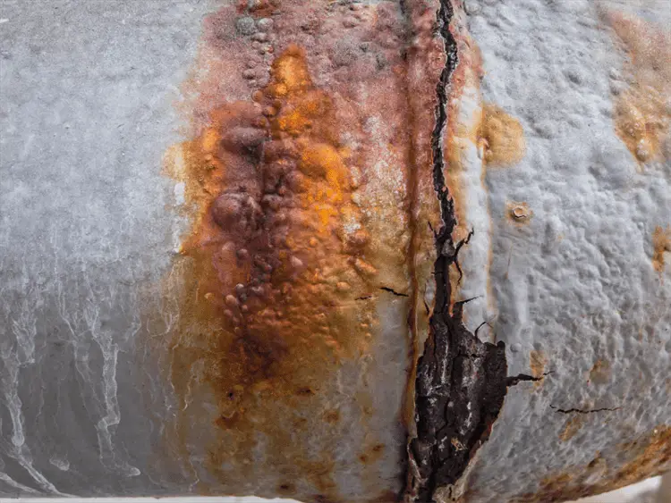
Other elements for stress corrosion cracking to occur are temperature and time. Fig. 1 below shows a typical example of stress corrosion cracking.
Fig. 1: Example of Stress Corrosion Cracking
The fracture processes in SCC are accelerated by the presence of cracks and other defects on the components. The failures caused by SCC are sudden and catastrophic in nature and are usually caused at much lower stress levels than yield stress. Some of the typical examples of SCC are listed below:
Seasonal cracking of brass in an ammonia-rich environment
Sensitization and stress corrosion cracking of stainless steels in presence of caustic, chlorides, and polythionic acid.
Types of Stress Corrosion Cracking
Depending on the actual SCC mechanism, various types of stress corrosion cracking are found.
Chloride Stress Corrosion cracking– prevalent in austenitic stainless steels in combination with tensile mechanical stress at a high-temperature condition in the presence of chloride ions and oxygen.
Caustic Embrittlement-Prevalent in stainless steels in the presence of a high hydrogen concentration under caustic environments.
SCC cracking of steels in hydrogen sulfide environment in oil and chemical industries.
Sessional Cracking-Cracking of brass in ammonia environments.
Craze Cracking-cracking of polymeric materials due to applied stress and environmental reaction.
Characteristic Features of Stress Corrosion Cracking
SCC has the following characteristic features:
Stress corrosion cracking failure occurs at stress levels much lower than the material yield stress.
The materials subjected to SCC are ductile but the failure mechanism is brittle.
The cracks in stress corrosion cracking are in general caused by corrosion.
At microscopic levels, intergranular and transgranular cracks are the major features of stress corrosion cracking. Intergranular cracks grow along grain boundaries but transgranular cracks proceed across the grains.
Materials Susceptible to Stress Corrosion Cracking
The following materials are prone to SCC attack:
Stainless steels (In the temperature range of 415°C to 850°C in chloride, caustic, and polythionic acid environment)
Carbon Steel (In carbonates, strong caustic solutions, nitrates, phosphates, seawater solution, acidic H2S, and high-temperature water environment)
Copper and copper alloys (In an environment containing ammonia, amines, and water vapor)
Polymers (In aggressive acid and alkali environments)
Ceramics
Stress Corrosion Cracking in Welding
The major cause attributed to stress corrosion cracking is the residual stress generated during welding and fabrication processes. In the stress corrosion cracking of metal alloys, the residual stress due to welding plays a crucial role. Stress corrosion cracking in welding is caused by non-uniform temperature changes during welding. Also, while welding certain steel grades, the solid-state transformation of austenite to martensite during cooling generates a significant amount of residual stresses. For carbon and low alloy steels, while quenching the austenite containing carbon atoms at a fast cooling rate, martensite is formed. In this situation, the carbon atoms do not get a chance to diffuse out from the crystal structure and form cementite. This increases the metal volume which results in significant residual stress.
Mechanisms of Stress Corrosion Cracking
Depending on the type of material and environment, various different Stress Corrosion cracking mechanisms are prevalent in the industry. Some of the well-known SCC mechanisms are:
Mechano-electrochemical model
As per this mechanism of stress corrosion cracking, in an alloy microstructure, there are pre-existing regions that become sensitive to anodic dissolution.
Film rupture model
For alloys having a passive layer on their surface, the film rupture SCC mechanism is well-known. In this mechanism, the corrosion starts following plastic deformation. The plastic strain disrupts the film which discloses the bare metal to the corrosive environment. Soon, a localized SCC attack starts in those areas and the process is repeated resulting in the growth of the cracking.
Adsorption phenomenon
The SCC mechanism considers the material embrittlement in the vicinity of a corroding area.
Pre-existing Active Path Model
Intermetallics and compounds are formed in the already existing paths like grain boundaries which are prone to SCC attack.
How to prevent Stress Corrosion Cracking?
As the mechanism of stress corrosion cracking is not yet fully understood, the prevention methods are based on empirical experiences. In general, one or more of the following methods can reduce the possibility of SCC:
As tensile stress is one of the major elements helping stress corrosion cracking, lowering the stress levels in components will reduce the potential of an SCC attack. By providing annealing treatment of the component, residual stress can be eliminated to a great extent.
Eliminating or decreasing aggressive species from the environment where the component is installed will serve as one method of reducing SCC attacks. For example, in the case of austenitic stainless steels, maintaining chloride content below 10 ppm significantly reduces the probability of SCC.
Selecting more stress corrosion cracking resistant materials will protect the product from stress corrosion cracking.
The application of cathodic protection reduces failures from stress corrosion cracking.
In mildly corrosive media, adding phosphate and other organic and inorganic inhibitors can reduce the stress corrosion cracking effects.
Hydrogen Induced Cracking (HIC) is a form of wet H2S cracking that is usually generated by high hydrogen concentration in metals. The mechanism involves atomic hydrogen which diffuses into a metal structure. The cracking due to HIC is formed parallel to the surface in the hoop stress direction. Hydrogen-induced cracking is more prevalent in sour service environments due to the presence of wet H2S. There are some other elements that may contribute to hydrogen-induced cracking. Some of these elements are arsenic, antimony, selenium, and cyanides. However, H2S is considered the most contributing element to hydrogen-induced cracking damage in the oil and gas industry. HIC causes blistering damage to many metals and alloys.
Hydrogen-induced cracking is more common in ferrous alloys due to its restricted slip capabilities in its BCC structure. HIC, in general, causes damage to steels with Rockwell C hardness of 22 or more at relatively low temperatures.
HIC can also occur during various elevated temperature processes like electroplating, pickling, phosphating, cathodic protection, arc welding, etc.
API Nelson curve provides a basis to understand the temperature zone over which the possibility of HIC increases. A typical curve indicating the HIC and Non-HIC zone is provided in Fig. 2 of the Sour Service article. Click here to refer to that article.
What is Hydrogen-Induced Cracking?
HIC = Hydrogen Induced Cracking = Caused due to Hydrogen attack on metal
Hydrogen-induced cracking is also known as
Hydrogen Damage
Hydrogen Embrittlement
Hydrogen Blistering
Delayed Cracking
Lamellar Tearing
Underbead Cracking
Stepwise Cracking
Hydrogen Induced Cracking Mechanism
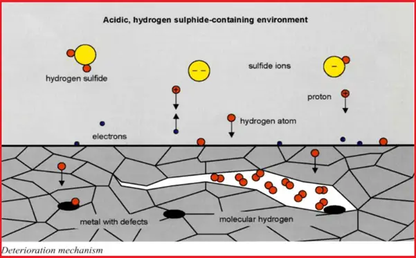
In a wet H2S environment, the HIC mechanism starts with the formation of atomic hydrogen that diffuses throughout the metal or alloy that collects at voids or impurities within the metal structure. When these hydrogen atoms combine to form a hydrogen molecule, it produces high pressure within the cavity. The H2S forces these hydrogen atoms into the metal structure which in turn reduces the ductility and tensile strength of the metal. Slowly, this mechanism reduces the metal ductility such that stepwise internal cracks are formed which is known as hydrogen-induced cracking.
Refer to Fig. 1 which shows the mechanism of HIC.
Fig. 1: Mechanism of Hydrogen Induced Cracking (HIC)
Exhibit – Hydrogen-Induced Cracking
HIC is often visible on the metal surface as horseshoe-shaped. Regular inspection and testing need to be performed for eliminating the possibility of hydrogen-induced corrosion. The damages by HIC can be detected by Wet Fluorescent Magnetic Particle Inspection. For cracked components Phased Array Ultrasonic Testing is the most widely used and reliable non-destructive method.
Low alloy steels and high-strength titanium and nickel steels are more prone to hydrogen-induced cracking. Low-strength steels with tensile strength below 1000 MPa are usually not susceptible to HIC. Copper, Aluminum, and their alloys are the most resistant to HIC.
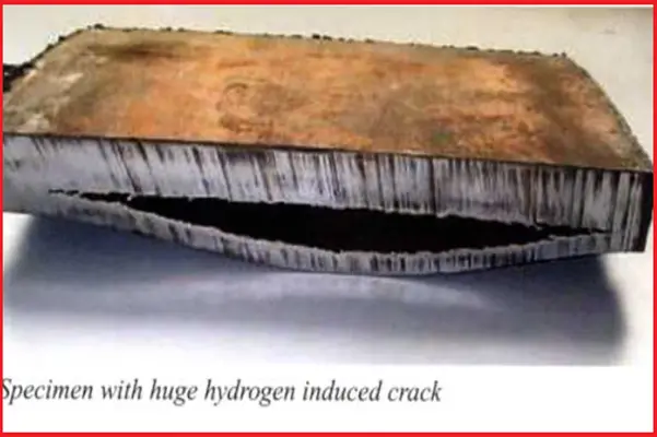
Fig. 2 shows an example of a crack by HIC.
Fig. 2: Example of Hydrogen Induced Cracking
Requirement of HIC Resistant Materials
Requirements for Carbon and Low Alloy Steels
The hardness of the Parent Material is Less Than 22HRC (237 BHN)
The steel shall be fully killed ( Silicon/Aluminum)
HIC test is performed following NACE TM0284. The unstressed HIC test specimen is exposed to the specified process environment saturated with hydrogen sulfide gas at 1 bar pressure for a duration of 96 hours (4 days) for the standard test. Fitness for purpose of testing is performed for durations of up to 30 days using reduced partial pressures of hydrogen sulfide.
Once the exposure period is finished, the test specimen is examined and any cracks developed are measured. The usual ratios that are used for hydrogen-induced cracking tests are the Crack Sensitivity Ratio, Crack Length Ratio, and Crack Thickness Ratio.
There is one more HIC test method known as Stress Oriented Hydrogen-induced cracking (SOHIC) test method. SOHIC test is performed following NACE MR0175 or ISO 15156 using the full ring test method as mentioned in BS 8701, tensile test method as mentioned in NACE TM0177-Method A, or four-point bend method as mentioned in NACE TM0316.
Thermal relief valves are also known as thermal safety valves, temperature relief valves, or thermal expansion relief valves. It is a safety device employed in liquid piping and pipeline systems to protect the equipment and system. When the thermal expansion of a liquid creates excessive pressure inside a closed system, the thermal relief valve pops up to release some fluid and bring down the pressure back to an acceptable limit. In general, when liquid heats up, it expands a little. When the temperature increase is quite high, the volume change of the liquid, though not by a large percentage, may increase the system pressure. To protect against this overpressure situation and to avoid explosion, thermal relief valves prove to be a good device.
What is a Thermal Relief Valve?
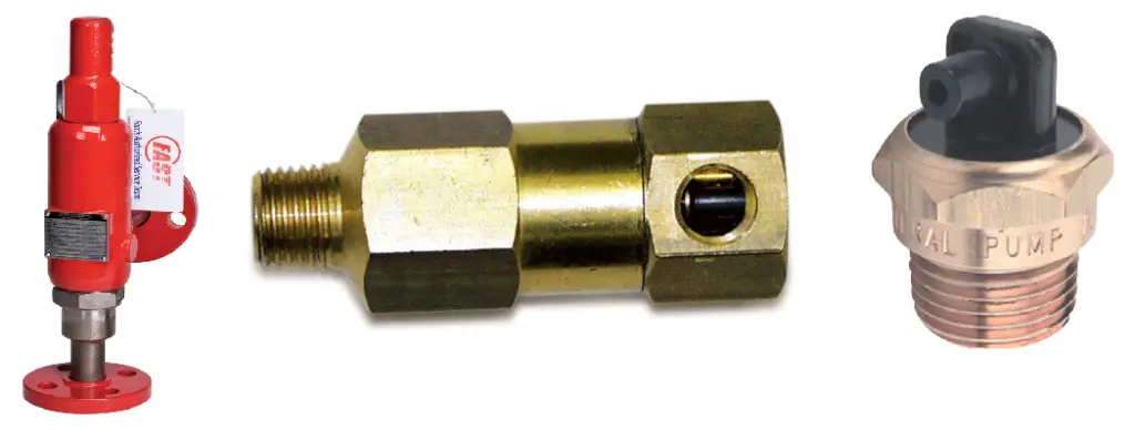
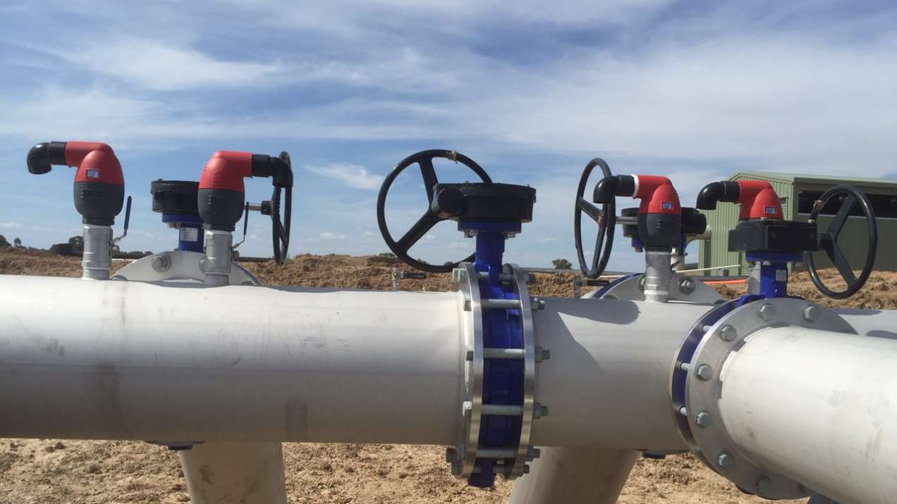
A thermal relief valve is a type of safety valve designed to release excess pressure from a system when it is subjected to temperature-induced expansion. When fluids or gases are heated, they expand, potentially leading to an increase in pressure that could exceed the system’s design limits. Thermal relief valves are engineered to mitigate this risk by allowing the excess pressure to escape, thus preventing potential damage or failure of the equipment. Fig. 1 below shows some typical thermal relief valves that are used in various industries.
Fig 1: Example of Thermal Relief Valves
Design Consideration for Thermal Relief Valves
The common size for thermal relief valves is relatively small. The usual size of thermal safety valves used for piping and pipeline systems are generally (1”x1”) or (¾”x1”) with a flanged end having a minimum orifice area of 0.110 in2.
Depending on the design code requirements a lifting device may or may not be required for thermal relief valves. In general, for air, hot water, or steam services with temperatures in excess of 600C lifting devices are normally specified.
Thermal relief valves are normally not vented directly to the environment. So, some sort of containment method is always suggested.
Thermal relief valves are usually designed based on API 526 or EN 14597 codes.
Applications of Thermal Relief Valves
Thermal safety valves are used for protection in case of excessive temperature for liquid applications in long pipes/pipelines exposed to the environment (sunlight), closed vessels, water heater applications, cooling water return side of heat exchangers between isolation valves, and pumps that recirculate water where heat buildup can be a problem. Piping in transport pipelines or storage areas, that will be regularly blocked during normal operation and can have a pressure rise due to solar heating or heat tracing calls for TRV installation.
The principal benefit of using a thermal relief valve in pump systems is that it allows an operator to run the unit in a bypass mode for an extended period, reducing the chances of premature seal wear on the high-pressure pump.
In general, thermal expansion relief valves are not intended for:
Process plant piping
Two-phase flow lines
Storage or transport piping sections that are not normally shut in for operational or emergency purposes
Systems that are not fully liquid filled, i.e. less than 95% liquid filled.
Thermal relief valves are employed in a variety of industries and applications. Some common areas where TRVs are used include:
Hydraulic Systems: In hydraulic systems, TRVs protect pumps, hoses, and other components from pressure spikes caused by thermal expansion. They ensure that the hydraulic fluid is maintained within safe pressure limits.
Compressed Air Systems: In air compressors and pneumatic systems, TRVs prevent pressure build-up due to temperature increases, safeguarding the compressor and associated equipment.
Boilers and Pressure Vessels: TRVs are crucial in boilers and pressure vessels to release excess pressure that may build up due to thermal expansion. This prevents catastrophic failures and ensures safe operation.
Chemical Processing: In chemical processing plants, where reactions can cause significant temperature and pressure changes, TRVs help maintain safe operating conditions by relieving excess pressure.
Working Principle of Thermal Relief Valves
TRV works mostly similarly to pressure relief valves. Even though the name is a thermal safety valve, the pressure increase is the main cause for its working. Under normal operation, the TRV remains closed by the spring force. When the force due to fluid expansion is great enough and exceeds the internal spring force, the valve pops up. Once the pressure reduces, the spring force again closes the thermal relief valve in a position to work smoothly.
Thermal safety valves work in an automatic manner and when the temperature falls below the set point it automatically reset.
Thermal relief valves are usually placed in a remote location without easy access. Also, normally temperature sensors, processors, or solenoid-type sensors are not used to control TRV systems. So, thermal expansion relief valves must be designed to be durable and work properly in case of system failure.
The basic mechanism of a TRV involves a spring-loaded valve that remains closed during normal operating conditions. When the system experiences a temperature-induced pressure rise, the valve opens to release excess pressure, thus protecting the system from damage.
Thermal Expansion: As temperatures increase, the fluid or gas inside a closed system expands. This expansion raises the internal pressure.
Pressure Threshold: The TRV is set to open at a specific pressure threshold. This threshold is usually predetermined based on the system’s maximum allowable working pressure.
Valve Actuation: Once the internal pressure exceeds the threshold, the TRV opens, allowing the excess fluid or gas to escape. This reduces the pressure back to a safer level.
Valve Closure: After the pressure decreases to a safe level, the TRV closes, and the system resumes normal operation.
Types of Thermal Relief Valves
There are three main types of thermal relief valves as mentioned below:
Spring-Loaded Thermal Relief Valves
Pilot-Operated Thermal Relief Valves
Balanced Bellows Thermal Relief Valves
1. Spring-Loaded Thermal Relief Valves
Description:
Mechanism: Utilizes a spring to keep the valve closed until the pressure exceeds a set point. When the pressure rises due to thermal expansion, it overcomes the spring force, causing the valve to open and release excess pressure.
Operation: The spring is calibrated to the pressure at which the valve should open. When the pressure increases beyond this point, the valve opens to relieve the excess pressure.
Advantages:
Simplicity: Straightforward design and operation.
Cost-Effective: Generally less expensive compared to more complex valve types.
Applications:
Commonly used in hydraulic systems, compressed air systems, and other systems where thermal expansion is a primary concern.
2. Pilot-Operated Thermal Relief Valves
Description:
Mechanism: Features a pilot valve that controls the main relief valve. The pilot valve responds to pressure changes and opens or closes the main valve accordingly.
Operation: The pilot valve operates at a lower pressure and controls the main valve to open at a higher pressure set point, providing precise control over the pressure relief process.
Advantages:
Precision: Offers more precise control of pressure relief.
High-Pressure Applications: Suitable for systems requiring accurate pressure control and handling higher pressures.
Applications:
Used in applications with high-pressure conditions or where precise pressure control is essential, such as in large-scale industrial systems.
3. Balanced Bellows Thermal Relief Valves
Description:
Mechanism: Includes a bellows element that helps to balance the pressure on both sides of the valve seat, reducing the effects of varying pressures and temperatures on the valve operation.
Operation: The bellows maintain a constant force on the valve seat, allowing it to open and close smoothly despite fluctuations in system pressure.
Advantages:
Stability: Provides stable operation under varying pressure and temperature conditions.
Reduced Sensitivity: Less affected by changes in the system’s pressure and temperature.
Applications:
Used in applications where pressure and temperature fluctuations are significant, such as in chemical processing or high-temperature systems.
Thermal Relief Valve Symbols
In P&IDs, the thermal relief valve symbol is provided as per Fig. 2 shown below:
Fig. 2: Symbol for Thermal Relief Valve (TRV)
The Importance of Thermal Relief Valves
Thermal relief valves (TRVs) are crucial components in various fluid and gas systems, serving essential roles in protecting equipment, ensuring safety, and optimizing performance. Here’s a detailed look at why thermal relief valves are important, using the key data provided:
1. Protection Against Catastrophic Failure
Thermal relief valves are crucial for protecting the integrity of systems from overpressure caused by temperature changes.
Prevention of Catastrophic Failures: When a system experiences a rise in temperature, the expansion of fluids or gases can lead to a significant increase in pressure. Without a TRV, this overpressure could exceed the design limits of the system, potentially resulting in catastrophic failures such as ruptures or explosions. By opening at a predetermined pressure, TRVs release the excess pressure, thus preventing such severe outcomes.
Cost Avoidance: Catastrophic failures often result in costly repairs or complete replacements of damaged equipment. By maintaining pressure within safe limits, thermal relief valves help avoid these significant financial burdens.
Safety Hazards Prevention: Overpressure situations can pose serious safety hazards to personnel working with or near the affected systems. By preventing overpressure, TRVs contribute to a safer working environment and help avoid injuries or fatalities.
2. Regulatory Compliance
Thermal relief valves are often required by industry standards and regulations, ensuring safety and legal compliance.
Adherence to Standards: Organizations such as the American Society of Mechanical Engineers (ASME) and the Occupational Safety and Health Administration (OSHA) mandate the use of thermal relief valves in specific applications. Compliance with these standards is not only crucial for legal reasons but also for ensuring the safety of personnel and the protection of the environment.
Avoidance of Legal Liabilities: Failing to comply with regulatory requirements can result in legal liabilities, fines, or penalties. By installing and maintaining TRVs as required, organizations can avoid such legal issues and ensure that their systems meet safety and operational standards.
3. System Performance and Efficiency
Thermal relief valves contribute to the optimization of system performance and operational efficiency.
Energy Waste Reduction: By releasing excess pressure, TRVs help prevent energy waste associated with overpressure conditions. This contributes to a more efficient operation of the system, as it avoids unnecessary strain and energy loss.
Reduced Wear and Tear: Excessive pressure can accelerate wear and tear on system components, leading to more frequent maintenance and shorter equipment life. TRVs help mitigate this issue by controlling pressure levels, thus extending the life of the components and reducing maintenance needs.
Improved Overall Performance: Maintaining optimal pressure levels helps ensure that the system operates efficiently and effectively. This can lead to enhanced overall system performance and reliability.
Difference between TRV and PRV
Even though the working mechanisms of both thermal relief valves (TRV) and Pressure relief valves (PRV) are almost similar, they have some differences.
A TRV is usually small, whereas a PRV can be of big sizes.
TRV acts when overpressure occurs because of temperature increases and relieves a small quantity of fluid, whereas PRV is sized to protect from any kind of overpressure and usually releases large quantities of fluid.
Safety is the main purpose of both TRV and PRV.
Thermal relief valves are vital components in various fluid systems, providing essential protection against pressure buildups caused by thermal expansion. Understanding their function, types, applications, and maintenance is crucial for anyone involved in the design, operation, or maintenance of hydraulic systems, compressors, or pressure vessels.
What is an Air Relief Valve, Air Release Valve, or Air Valve?
Air Relief Valves are popularly known as Air Release Valves or Air Valves. Air Relief Valves work as a safety device by releasing the air pockets that may be generated at each high point of a fully pressured pipeline. If not released, this trapped air may cause various problems like flow issues, pump failures, corrosion, faulty instrumentation readings, and pressure surges. Also, air trapped in the pipeline system calls for additional energy consumption. So, air relief valves function as a very important element in such situations.
Air can enter into a pipeline from the following sources:
The pipeline itself – Before commissioning and start-up of any pipeline, it is filled with air. When fluid enters the pipe, it displaces the air and takes its position. The air must be completely removed during this stage otherwise it will accumulate at the highest points.
Water usually contains 2% air by volume. Adhesives or other thick fluids normally trap air in pockets. So, when the fluid flows through the system, sometimes air separates out from the mixture/pockets and accumulates at system high points.
Several pieces of equipment like pumps, packing, valves, and pipe joints can also suck air which then can accumulate at the high points.
This accumulated air creates flow restriction which increases the pressure head loss. This increases pumping cycles, which translates into higher energy consumption.
At the same time, while flowing through the restricted pipe, its velocity increases. With the increase in velocity, it may be possible that part or all of the air pocket will break away and be carried downstream. This increases the possibility of a water hammer which is known to cause serious damage to pumps, valves, and pipes. It is, therefore, air accumulation in system high points must be avoided.
Again, when the fluid velocity is not sufficient enough to carry away the air pockets, they continue to grow. Larger air pockets make the system completely air bound and create flow stoppage.
Air release valves or air relief valves work continuously to eliminate excess air from the system which in turn results in a smooth and efficient operation.
Air release valves open against internal pressure and release the system’s accumulated air. Air Release Valves are widely used for increasing pipeline efficiency and water hammer protection.
Fig. 1: Typical Air Release Valves in a Pipeline
Working of Air Release Valves
Automatic air release valves are located at the highest points of the pipeline or other systems where air naturally collects. The air bubbles enter the air relief valve and displace the inside liquid. Thus the liquid level is lowered. When the liquid level drops to such an extent that it no longer buoys the float, the float drops causing the valve to open which vents the accumulated air into the atmosphere.
Once the air is released, the liquid re-enters the valve, lifting the float until the seat presses against the orifice, and closing the valve. This cycle continues automatically and maintains an air-free system.
Components of an Air Release Valve
An air release valve or air valve consists of the following components:
Main Body: Compact metal body that houses the inner floats and upper mechanism.
Inner Float Assemblies that consist of a large orifice float, small orifice float, upper float, upper seat, mesh outlet, and cover.
Proper Installation of Air Relief Valves
Air release valves must be installed at high points where the air is likely to be collected in the piping or pipeline system. It is preferable to install the device in the vertical position with the inlet down. If servicing is required, a shut-off valve must be added below the air relief valve. In general air relief valves or air valves are installed in the following locations:
Air relief valves are popular for water pipelines and sewer force mains. However, they are ideal for any type of closed-loop or pressurized piping or pipeline system that has the chance of entrapping air.
Compared with other types of air valves, air release valves have small orifices. So, the best application for air relief valves is the applications with smaller volumes of air to exhaust.
Advantages of Air Relief Valves
Air release valves provide the following benefits:
They protect the pipeline and piping system.
They maintain the system’s efficiency by reducing pressure loss.
They are automatic.
They continuously vent entrapped air from high points.
They are also used to allow air back into the pipeline during emptying the liquid.
Disadvantages of Air Relief valves
Air release valves are usually not suitable for quick filling or emptying of pipelines. In such situations, air relief valves must be accurately sized for the specific application.
So, overall air release valves safeguard the pipeline and pumping system from damage. They lower energy consumption increase efficiency, and eliminate surge potential and hence, must be installed in every system having the possibility of air accumulation.
What is Pipe Spacing? Pipe and Pipeline Spacing Chart
Pipe spacing refers to the specific distance maintained between adjacent pipes in a piping system. Proper spacing ensures that pipes do not interfere with each other during thermal expansion, maintenance, or operational movements. It also helps in avoiding mechanical damage and provides sufficient room for inspection and repairs.
Why is Pipe Spacing Important?
Maintenance and Accessibility: Adequate spacing allows for easier access to pipes for routine maintenance, repairs, and inspections.
Thermal Expansion: Pipes expand and contract with temperature changes. Proper spacing accommodates these movements to prevent clashing and potential damage.
Safety: Sufficient spacing helps avoid mechanical interference and reduces the risk of leaks or system failures.
Optimized Layout: Efficient spacing can minimize the footprint of pipe racks, reducing construction costs and saving space.
Factors Influencing Pipe Spacing
Several factors must be considered when determining the appropriate spacing between pipes:
Pipe Diameter, Flange Rating, and Size: Larger pipes and flanges require more space. The diameter of the pipes and the size of their flanges (if applicable) significantly influence the spacing.
Insulation Thickness: If pipes are insulated, the thickness of the insulation must be considered when calculating spacing.
Thermal Movement: Pipes experiencing significant thermal expansion or contraction require additional spacing to accommodate these movements.
Pipe Racks and Supports: In pipe racks, spacing must account for the arrangement of flanges and the type of supports used.
What is a Pipe Spacing Chart?
A Pipe Spacing Chart provides the minimum distance between two adjacent pipes or pipelines. Whenever two pipes run parallel to each other, piping designers or engineers must maintain a minimum gap between the two pipes or pipelines.
Placing the pipes in proper order following a pipe spacing chart provides various benefits like:
Proper pipeline spacing prevents the clash between pipes/pipelines during construction and erection.
Sufficient Spacing accommodates sideways thermal movement of pipes generated due to thermal or occasional movements.
So, to fulfill the above requirements and help pipeline and piping engineers during their pipe-laying activities, organizations prepare a standard pipe spacing chart. Following those standardized pipe spacing charts, the activities become quicker, and the chances of error during pipe and pipeline placement are reduced a lot. So, in a sentence, we can define a pipe spacing chart as a tabular representation of minimum pipe-to-pipe distances of various sizes.
Pipe spacing charts are very useful while routing pipes over a pipe rack or sleepers where lines of various sizes run parallel to each other.
Pipe Spacing Criteria
Various factors need to be taken one while piping or pipeline spacing. Some of those factors are:
Adequate space for maintenance, inspection, and component repair must be provided during the layout.
Spacing should be considered the worst free thermal movement between pipes. When the thermal movement is large, additional pipe spacing must be considered so that pipe thermal displacement is accommodated.
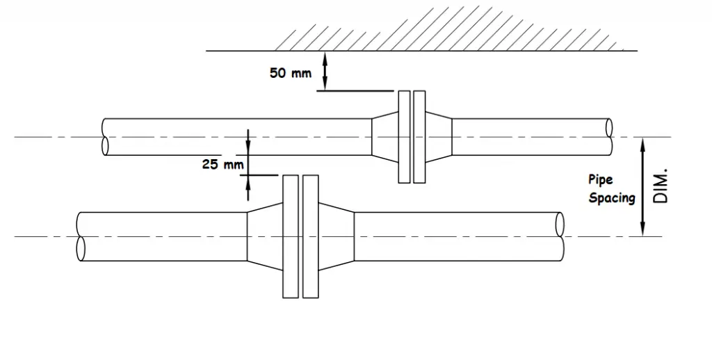
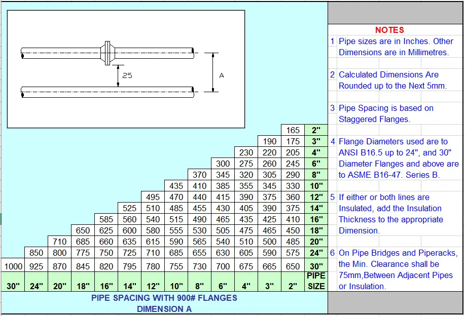
The usual practice to develop a pipe spacing chart is to consider a 25 mm gap between the outermost periphery of the piping components. So for example, if there are two pipes running parallel to each other, one having insulation and the other having a flange connection, a minimum of 25 mm gas has to be maintained in between the Insulation surface and flange surface. If both lines have a flanged connection, the flanges must be staggered to reduce pipe spacing between the two.
The formula for pipeline spacing:
The basic formula that is generally used to develop a pipe spacing chart is:
Centre to center distance between two adjacent pipes (mm)=half outer diameters of the bigger size pipe flange (OD/2)+half outside diameter of smaller size pipe (od/2)+ insulation thickness of both the smaller and bigger size pipe as applicable (T+t)+ 25 mm +Thermal displacement=(OD+id)/2 + (T+t) + 25 +Thermal displacement
The Pipe Flange Outer diameter is available in the flange standard. For example, ASME B16.5 is used for flanges up to 24″ in size and ASME B16.47 is used for flanges of size 24″ to 60″. AWWA C207 is used for flanges above 60 inches in size. For custom flanges or flanges designed with other standards, you have to refer to that standard.
Pipe outside diameter you will get in ASME B36.10/B36.19 standard.
Pipe insulation thicknesses, you will get in the project-specific insulation specifications. That will be a project-specific in-house document and can vary from project to project depending on the design criteria.
Thermal displacement needs to be calculated based on the worst situation consideration. For example, if two lines are running parallel to each other. One has a design temperature of 2500C (hotline) and the other has a design temperature of -460C (cold line). So, the hot line will expand and the cold line will compress. So, while calculating the pipe span both this displacement needs to be added. This means if the hot line expands by 30 mm and the cold line compresses by 15 mm then the thermal displacement that needs to be added in the pipe spacing calculation is 30+15=45 mm. However, if both lines are hot lines, then while thermal displacement calculation, consider a situation when one pipe is operating and the other is in ambient condition (preferably consider winter’s lowest ambient temperature).
So, using the above parameters in the above equation, you can easily calculate the pipe-to-pipe distance requirement for pipes of any size.
Fig. 1: Pipe Spacing Explanation
Pipe Spacing Chart
Standard pipe spacing charts are developed by organizations that provide center-to-center distance between two pipes. If there is a considerable amount of lateral thermal displacement (usually >15 mm) then the same needs to be added with the spacing values given in the standard pipe spacing charts. Typical pipe spacing charts are provided below to get an idea of the pipeline spacing charts used in the piping industry. However, these values may vary depending on the component design codes. So, it is always better to practice calculating using the above formula.
Pipe Spacing chart for pipes with 150 rating flanges
Fig. 2: Pipe Spacing chart for pipes with 150-rating flanges
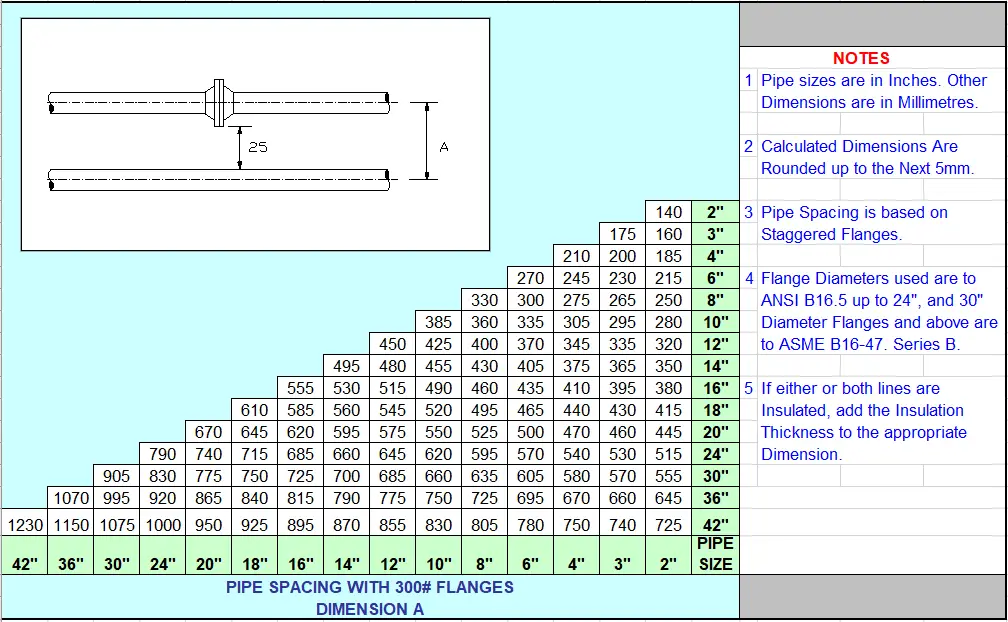
Pipe Spacing chart for pipes with 300-rating flanges
Fig. 3: Pipe Spacing chart for pipes with 300-rating flanges
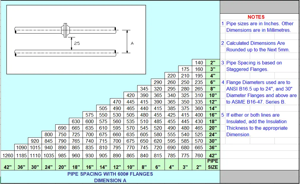
Pipe Spacing chart for pipes with 600 rating flanges
Fig. 4: Pipe Spacing chart for pipes with 600-rating flanges
Pipe Spacing chart for pipes with 900 rating flanges
Fig. 5: Pipe Spacing chart for pipes with 900-rating flanges
Using a Pipe Spacing Calculator
A pipe spacing calculator is a valuable tool for determining the correct spacing between pipes based on various criteria. Here’s how to use it:
Select the Configuration: Choose from the four provided options, such as spacing between pipe centers, flange centers, or bare pipes.
Input Dimensions: Enter the outer diameter (OD) of the pipes and flanges. For configurations involving flanged components, include the OD of the flanges.
Calculate Spacing: The calculator will provide the minimum spacing required between pipes based on your input.
Spacing Between Pipes on a Pipe Rack
When pipes are arranged on a pipe rack, specific considerations are required:
Staggered Flanges: If adjacent lines have flanged components, staggered arrangement is often necessary to optimize space and reduce the required footprint.
Clamped Supports: If using clamped supports, larger spacing may be required. For cost-effectiveness, clamped pipe supports at a 45-degree angle are recommended.
Special Considerations
Protruding Valves: For valves like full-bore ball valves with higher flange ratings, the valve body may extend beyond the flange OD. In such cases, specific calculations are needed to ensure adequate spacing.
Non-Staggered Components: If flanged components cannot be staggered, ensure that the spacing accounts for the largest flange OD and any additional clearances.