Drying is a process where moisture is removed from a wet material or a gas to make it dry. This technique is often used in different industrial operations like sugar production, milk powder production, soap bar production, etc. The energy for drying is supplied by external means like hot gas or air.
Vacuum drying is a process where heat-sensitive material is dried by reducing its pressure as we know by reducing pressure moisture can be removed easily at relatively lower temperatures. Because character tics of heat-sensitive materials can be degraded on exposure to hot air or gas.
Drying Mechanism
Drying is dependent on the principles of mass & heat transfer. Moisture vaporizes at the solid surface while the solid is heated to a sufficient temperature. The heat required (Sensible heat & heat of vaporization) for drying is usually supplied by hot air or gas. After the vaporization of surface moisture, more moisture is transported from inside the solid to its surface. The different types of mechanisms may be classified into
- Liquid diffusion
- Pressure-induced transport
- Vapor diffusion
- Capillary force
Different Types of Moistures
- Moisture content: It is the quantity of moisture in wet material. It is generally expressed in mass ratio units (kg moisture/kg of dry solid).
- Bound Moisture: The amount of moisture in a solid that causes a vapor pressure less than the normal vapor pressure of water at the given temperature is called bound moisture.
- Unbound Moisture: The amount of moisture in a wet solid in excess of the bound moisture is called unbound moisture.
- Equilibrium moisture: It is the moisture content in a solid that is in equilibrium with the drying medium of a given temperature & relative humidity.
- Free moisture: It is the moisture content in a solid in excess of the equilibrium moisture. Only free moisture can be removed by drying under a given set of conditions.
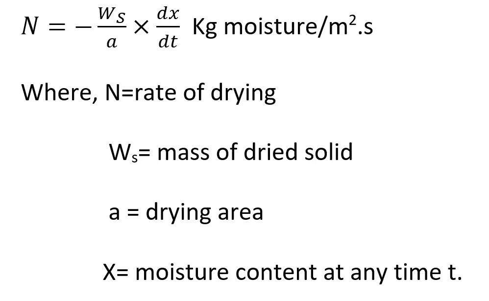
The Drying Rate Curve
The time taken by drying operation of a moist solid to final moisture content can be determined from the rate of drying under certain conditions. The drying rate is a function of the temperature, humidity, flow, and transport properties of drying gas. The drying rate (N) is determined by the experiment method. Refer to the equation given in Fig. 1 below
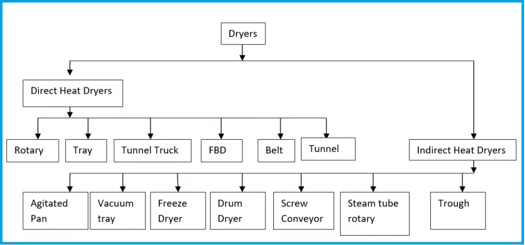
Types of Dryers
There are several types of dryers available to suit specific needs as a wide variety of wet solids, slurries, and solutions are required to be dried on an industrial scale. The performance of a dryer depends on how good the contact between the wet solid and the drying gas is.
Tray Dryer
A tray dryer is the most common type of dryer generally used in industries where cross-circulation drying occurs. The moist solid is taken in a number of trays; the trays are stacked in the drying chamber providing a gap so that drying gas may be passed over the exposed top surface of the solid spread on a tray. The drying gas (usually air) is heated in contact with steam coils. A blower fitted inside the cabinet forces the hot air over the trays. A portion of the air is circulated inside the cabinet and the rest leaves the chamber carrying evaporated moisture. The temperature, humidity, and velocity of air may be regulated by adjusting the gas flow rate.
Advantages of Tray Dryer:
- -Each batch is dried & handled separately
- – It’s more feasible in consumption of fuel
- -Easy to clean, accessible, and control
- -Less space requirement
- -It’s operated batch-wise
- -It provided a tendency to over-dry the lower trays.
- -It requires small labor costs for loading & unloading trays.
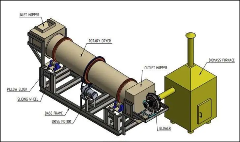
Rotary Dryer
Rotary dryers are often called the ‘workhorse of chemical dryers’ and fall in the most widely used class of continuous dryers in process industries. It consists of a slowly rotating slightly inclined cylindrical shell fed with moist solid at the upper end. The material inside a rotary dryer flows along with the rotating shell, gets dried, and leaves the dryer at the lower end. The heat for drying is provided by a hot flue flowing outside and heat is transferred through the shell.
Countercurrent flow in a rotary dryer ensures a more uniform distribution of the temperature-driving force along with the shell.
What is a rotary dryer used for?
This type of dryer is suitable for relatively free-flowing, non-sticky, and granular materials e.g. almost all types of crystals after crystallization and washing such as table salt, sodium sulfate, ammonium sulfate, minerals, and organic salts. Also, it is used for dehydrating waste materials, and animal feedstuffs.
Vacuum Dryer
The vacuum dryer is provided with a heating jacket and slow-moving agitator for wet material. A moderate vacuum usually not below 10 mm Hg is used. The vapor drawn by the vacuum device may be condensed if recovery is desired. The conical shape allows faster discharge of the dry product through the bottom. This type of dryer is used for drying powders, dyes, chemicals & pharmaceuticals.
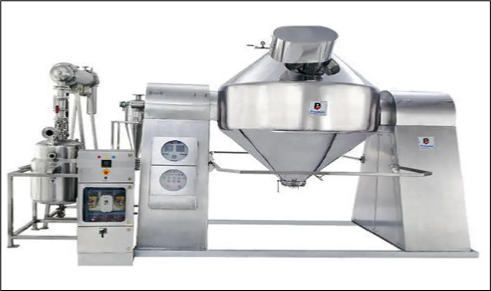
How does a vacuum dryer work?
It is a batch operation where the pressure and humidity are reduced by means of vacuum pumps in an air-tight vessel. Thus, by lowering the atmospheric pressure in the chamber the materials inside the vessel dry more rapidly through contact with heated walls indirectly.
Advantages of Vacuum drying:
- Vacuum drying is a process, where heat-sensitive, toxic powders and hygroscopic & granules have been dried by avoiding exposure of excess heat as well as certain nutrients, which can break down on exposure to excess heat. Taste, appearance, and other properties may degrade under too much heat.
- Vacuum drying employs a safe & highly effective technique for drying large volumes of heat-sensitive granules or powders. The temperature is usually very low compared to what will be required in a common industrial dryer.
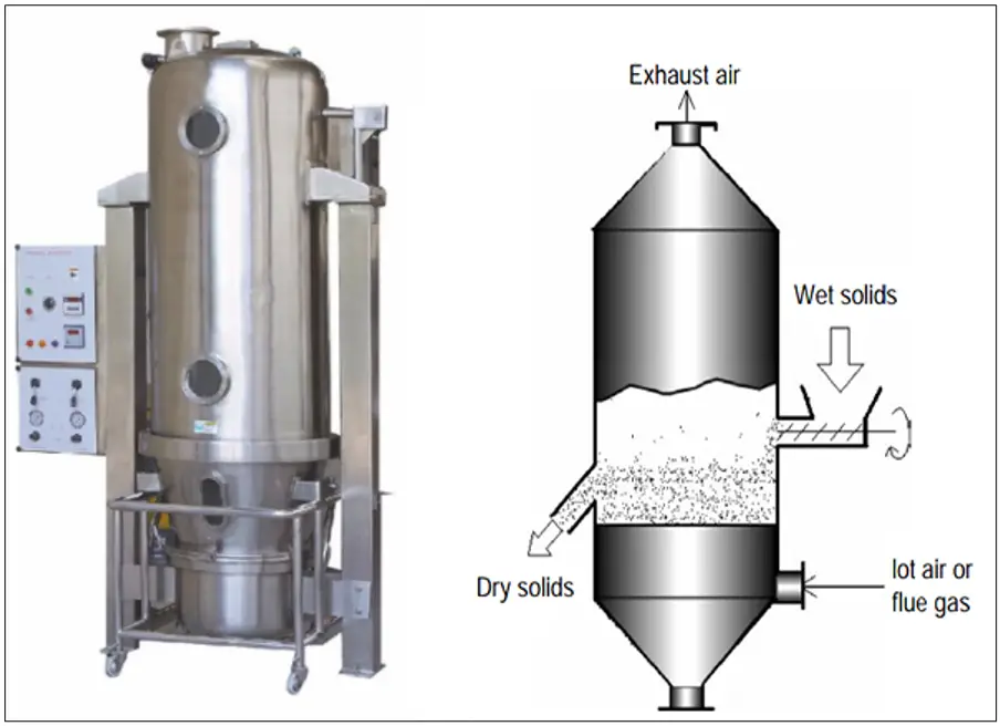
Fluidized-bed Dryer
This type of dryer is used for drying free-flowing moist solids. The working principle is very simple. The moist solid is fed continuously into the dryer by a screw feeder and is kept fluidized by a stream of hot drying gas. The dry product is also continuously removed through a nozzle at an appropriate location. The fines carried over by the gas are separated in a cyclone separator or bag filter. A fluid-bed dryer is widely used to dry a variety of materials such as minerals, pharmaceuticals, seeds, cereals, spices, fish meals, waste materials, etc.
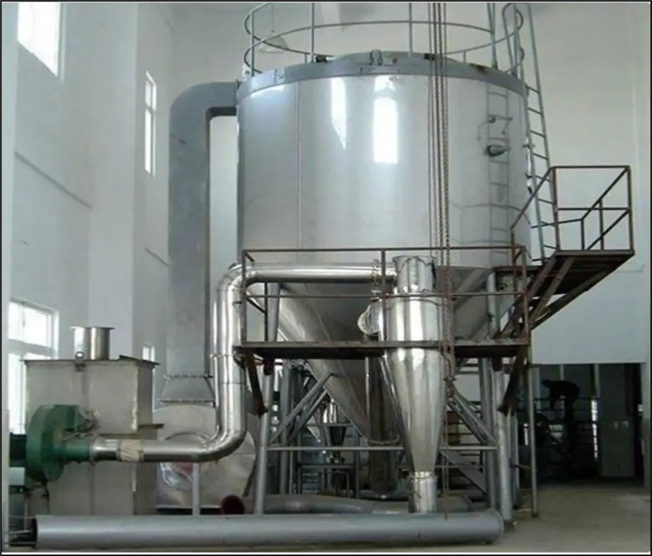
Spray Dryers
A spray dryer is installed to dry the atomized droplets contained in the feed that may be a solution or slurry of fine particles. It consists of a big drying chamber which may be 15m in diameter and 35 m tall.
How does a spray dryer work?
The feed is fed through an atomizer located at the top. The hot gas is introduced either at the top or at the bottom (concurrently or counter currently). The hot gas temperature may be as high as 700ᵒC but normally is kept within 250-280ᵒC. Drying of the droplets dispersed in the hot gas occurs in a very short contact time of a few seconds. The process of atomization of the feed is performed by a rotating disk and a high-pressure nozzle. The liquid or slurry is fed onto the disk at the center which is centrifugally accelerated and then ejected from the periphery of the disk at a speed of 80-200 m/s. The angular velocity of the disk is 3000-20000 rpm.
Advantages of Spray dryer:
- The spray dryer can atomize handle abrasive slurry or paste using a whirling disk without erosion.
- It is also considerably flexible with respect to feeding rate and properties.
- The size of the atomized droplet is 10-20 microns
- Due to its conical bottom shape small dried particle is removed through a product conveying line.
- Because of the very short contact time between droplets and the drying gas. A spray dryer is suitable for drying heat-sensitive materials.
- A spray dryer is also used to dry a variety of other liquids, e.g. milk, egg, coffee, tea, tannin some polymeric resins, pharmaceuticals, organic and inorganic activated pharmaceuticals ingredients, detergents, etc.
Selection of Industrial Dryers
The following data need to be collected before the selection of dryers.
- The physical form of feed – Liquid, slurry, pasty, free-flowing powders, granular, crystalline, continuous sheet, discontinuous sheet.
- Dryer throughput (Kg/hr).
- Upstream/Downstream equipment – batch or continuous.
- For particulate feed products, mean particle size and size distribution.
- Inlet/outlet moisture content of the product.
- Maximum allowable product temperature.
- Drying curve.
- Feed cohesiveness.
- Product fragility.
- Contamination by drying gas.
- Explosion characteristics (vapor/air and dust/air).
- Toxicological properties.
- Corrosion aspects.
- Product value.
- Experience already gained.
A typical decision tree diagram is provided in Fig. 7 and Fig. 8 below for the selection of batch dryers and continuous dryers.
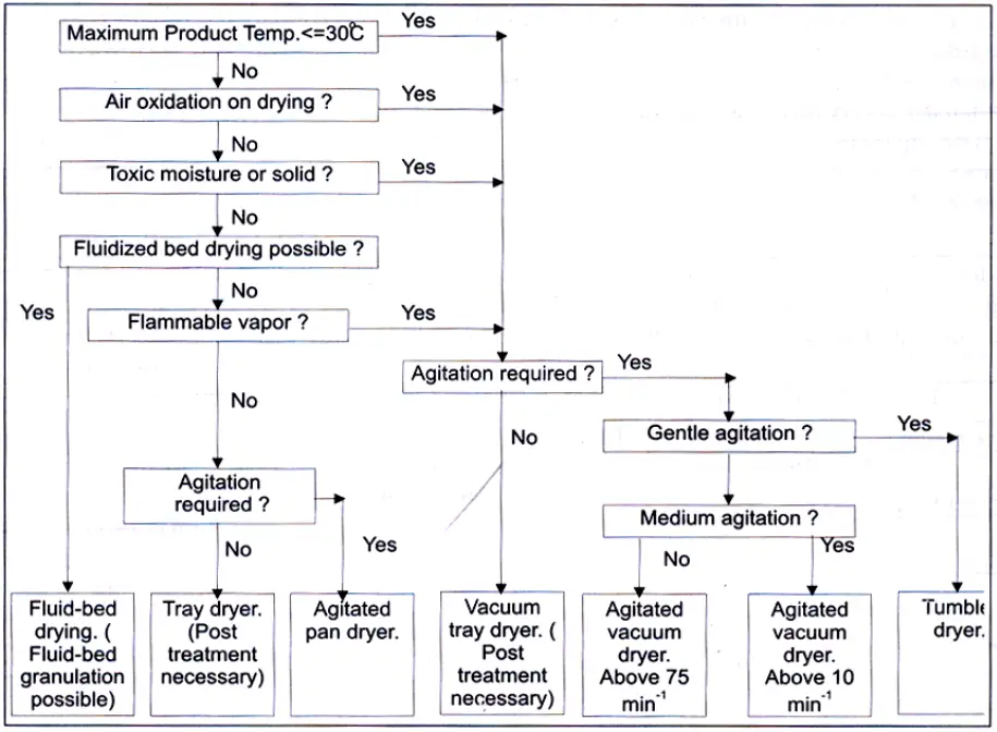
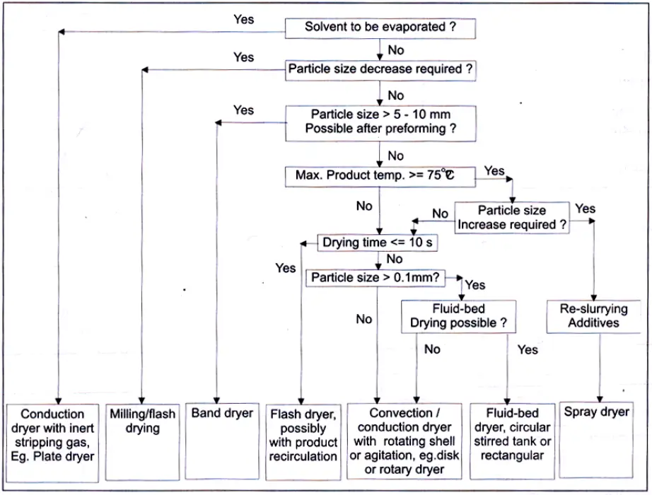
Proper dryer selection is a challenging issue and has a significant impact on the economic growth of a plant, it is not at all recommended to fully depend on the vendors’ information & recommendation but users should come up with preliminary criteria for dryer selection prior to contacting any vendor. The above decision trees for the selecting batch and continuous dryers can be used during the initial assortment of a large number of dryers.